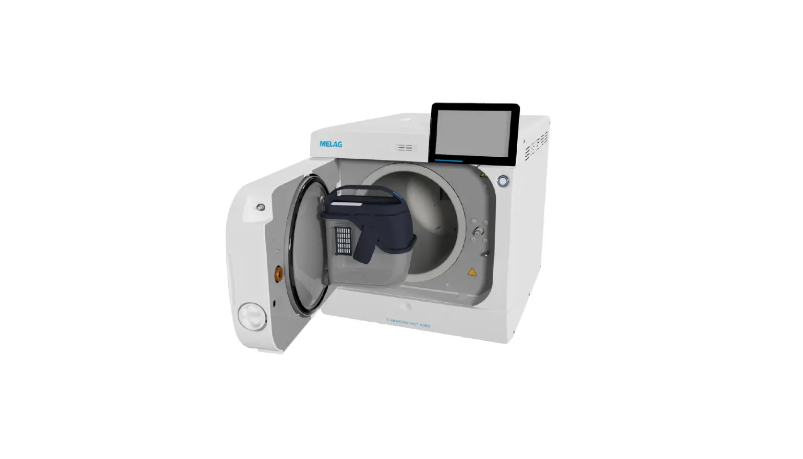
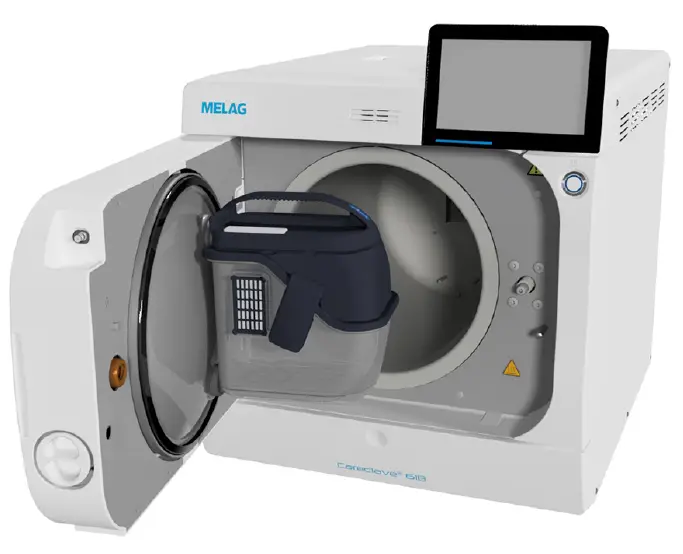
MELAG Careclave 618 Combination Steam Sterilizer
Product Information
The Combination steam sterilizer is a technical device designed for sterilizing instruments and practice fittings. It is equipped with software version 21.0.3 and is intended for use outside the patient area. The product comes with a user manual that contains important safety information. The manual should be stored carefully and kept in close proximity to the device.
Symbols Used
- Indicates a dangerous situation, which if not avoided, could entail slight to life-threatening injuries.
- Burns Indicates a dangerous situation, which if not avoided, could lead to burns.
- Damage Draws your attention to a situation, which if not avoided, could result in damage to the instruments, the practice fittings, or the device.
- Important Information Draws your attention to important information.
Product Usage Instructions
Installation Requirements
Installation Location:
- The steam sterilizer should only be set up, installed, and commissioned by persons authorized by MELAG.
- The steam sterilizer is not suitable for operation in explosive atmospheres.
- The device should be located a minimum of 1.5 m radius away from the treatment area.
Property Installation Surface:
The steam sterilizer should be installed on a level and horizontal interior surface of a building that is dry and protected from dust.
- Max. Altitude: The device is suitable for operation at altitudes up to 2000 m.
- Overvoltage Category: The device can handle transient overvoltage up to the values of overvoltage category II 2.
- Degree of Contamination (in accordance with EN 61010): The device is suitable for use in environments with a degree of contamination in accordance with EN 61010.
- Operating Weight: The steam sterilizer has an operating weight of 1.7 kWh.
Floor Loading:
- Floor loading during normal operation should be considered.
- Floor load during hydraulic pressure test should be considered.
Ambient Temperature:
The device should be operated within the specified ambient temperature range.
Relative Humidity:
The device should be operated within the specified relative humidity range.
Space Requirements
Dimensions:
- Width: Specify the width of the device.
- Height: Specify the height of the device.
- Height without color touch display: Specify the height of the device without the color touch display.
- Depth: Specify the depth of the device.
Clearance:
- Clearance between the device feet: Specify the clearance between the feet of the device.
- Clearance from rear device foot up to the cover: Specify the clearance from the rear foot of the device up to the cover.
- Min. clearance to the side: Specify the minimum clearance required to the side of the device.
- Min. clearance to the side of the door hinge: Specify the minimum clearance required to the side of the door hinge.
- Min. clearance to the rear: Specify the minimum clearance required to the rear of the device.
- Clearance when door fully open: Specify the clearance required when the door is fully open.
- Max. clearance with open door: Specify the maximum clearance required with the door open.
- Min. clearance to the top: Specify the minimum clearance required to the top of the device.
Follow these installation requirements carefully to ensure safe and proper setup of the Combination steam sterilizer.
Read this manual carefully and in the correct order before setting up and commissioning the device. The instructions include important safety information. You also receive a user manual with the device. Please store this manual and the user manual carefully and in close proximity to the device. They represent a component of the product.
General guidelines
Read this manual carefully and in the correct order before setting up and commissioning the device. The instructions include important safety information. You also receive a user manual with the device. Please store this manual and the user manual carefully and in close proximity to the device. They represent a component of the product.
Should the manual no longer be legible, is damaged or has been lost, you can download a new copy from the MELAG download center at www.melag.com.
Symbols used
| Explanation |
| Indicates a dangerous situation, which if not avoided, could entail slight to life-threatening injuries. |
| Indicates a dangerous situation, which if not avoided, could lead to burns. |
| Draws your attention to a situation, which if not avoided, could result in damage to the instruments, the practice fittings or the device. |
| Draws your attention to important information. |
Formatting rules
| Example | Explanation |
| Universal-Pro- gram | Words or phrases appearing on the display of the device are marked as display text. |
| Prerequisites for the following handling instruction. | |
| Refer to the glossary or another text section. | |
| Information for safe handling. |
Installation requirements
Installation location
WARNING
Failure to comply with the setup conditions can result in injuries and/or damage to the steam sterilizer.
- The steam sterilizer should only be setup, installed and commissioned by persons authorised by MELAG.
- The steam sterilizer is not suitable for operation in explosive atmospheres.
- The steam sterilizer is conceived for use outside the patient area. The device should be located a minimum of 1.5 m radius away from the treatment area.
| Property | Careclave 618 |
| Installation surface | level and horizontal |
| Installation location | interior of a building (dry and protected from dust) |
| Max. altitude | 2000 m |
| Overvoltage category | transient overvoltage up to the values of overvoltage category II |
| Degree of contamination (in accordance with EN 61010) | 2 |
| Operating weight | 82.5 kg |
| Floor loading (normal operation) | 2.6 kN/m² |
| Floor load (hydraulic pressure test) | 2.91 kN/m² |
| Heat emission per hour (with maximum load) | 1.7 kWh |
| Ambient temperature | 5-40 °C (ideal range 16-26 °C) |
| Relative humidity | max. 80 % at temperatures of up to 30 °C, max. 50% at 40 °C (decreasing in linear fashion in-between) |
Steam egress can occur during operation. Do not set up the device in the immediate proximity of a smoke detector. Maintain clearance from materials which could suffer damage from steam.
Electromagnetic environments
When assessing the Electromagnetic Compatibility (EMC) of this device, the emitted interference threshold values for Class B devices and the stability for operation in an electromagnetic environment as described in IEC 61326-1 were tak-en as the basis. The device is thus suitable for operation in all institutions and domestic settings connected to a public mains power supply. The floor should be made of wood or concrete or be tiled with ceramic tiling. If the floor is fitted with synthetic material, the relative humidity must amount to a minimum of 30 %.
Space requirements
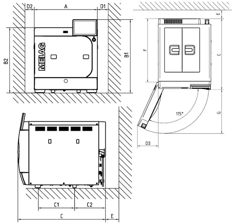
| Dimensions | ||
| Width | A | 48 cm |
| Height | B1 | 56.2 cm |
| Height without colour touch display | B2 | 49.7 cm |
| Depth | C | 65.3 cm |
| Clearance between the device feet | C1 | 27.05 cm |
| Clearance from rear device foot up to the cover | C2 | 23.1 cm |
| Min. clearance to the side | D1 | 7 cm |
| Min. clearance to the side of the door hinge | D2 | 3 cm |
| Min. clearance to the side | D3 | 19 cm |
| Min. clearance to the rear | E | 1 cm |
| Clearance when door fully open | F | 58 cm |
| Max. clearance with open door | G | 38.5 cm |
| Min. clearance to the top | B1 + 4 cm | |
Above, the device should be freely accessible to ensure access to the storage tank and the accessories compartment and to ensure good ventilation. The device operates with a cooler at the back of the device. The function and life-span can be compromised if heat dissipation via the cooler is restricted in any way. Installation of the device is therefore strongly discouraged and only possible if sufficient air circulation is ensured, e.g. with an exhaust shaft in the upper rear area of the cupboard unit. To ensure good access, it must be possible to pull the device out of the cupboard unit.
Additional space requirement for the feed water supply
Additional space is required for a storage container or a water treatment unit. It is also necessary to guarantee free ac-cess to the hoses and cables leading from from the device to the water treatment unit.
| Space require- ments | MELAdem 47 | Storage container | |
| Osmosis module | Storage tank | ||
| Width | 42 cm | Ø 24 cm | 21 cm |
| Height | 47 cm | 51 cm | 38 cm |
| Depth | 15 cm | — | 23 cm |
Space is required above the MELAdem 53 / MELAdem 53 C for free access to the hose connections.
| Dimensions | MELAdem 53 | MELAdem 53 C |
| Diameter | 24 cm | 24 cm |
| Height of the unit incl. connecting parts | 57 cm | 45 cm |
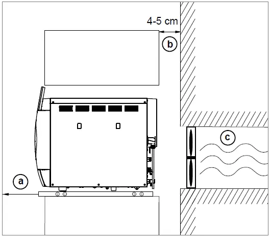
Requirements for the installation of a device
If the installation of the device is mandatory, one of the following measures must be implemented:
- It must be possible to pull out the device for operation (pos. a).
- There must be an exhaust air shaft in the rear area of the installation space that discharges the warm air upwards (pos. b).
- There must be an exhaust air shaft in the rear area of the installation space that discharges the warm air to the rear (pos. c).
Mains supply
Implement the following safety measures when dealing with the cable and power plug:
- Never damage or alter the power plug or cable.
- Never bend or twist the power cable.
- Never remove the plug by pulling on the power cable. Always take a grip on the plug.
- Never place any heavy objects on the power cable.
- Never run the power cable over areas in which it could become trapped (e.g. doors or windows).
- Never lead the cable along a source of heat.
- Never use any nails, paper fasteners or similar objects to fix the cable.
- Should the power plug or cable suffer damage, switch off the device. The power cable or plug should only be replaced by authorised technicians.
- The power cable may not be replaced by a cable determined to be insufficient.
- The mains socket must be freely accessible after installation so that the device can be disconnected from the electrical mains at any time if necessary by pulling the power plug.
| Property | On-site requirements |
| Power supply | 220-240 V 50 Hz Fluctuations of the mains supply voltage up to ± 10% of the nominal voltage |
| Max. power consumption in operation | 3000 W |
| Building fuse protection | Separate circuit with at least 13 A, RCD with rated residual current = 30 mA (to ensure continued operation of the device in practice in case of malfunctions) |
| Other | Additional socket 220-240 V, 50 Hz for printer MELAprint 60/80 |
| Length of the power cable | 2 m |
| Disconnecting device | Power connector |
Water connection
| Feed water | Wastewater | |
| Connection in the practice | to a water treatment unit, e.g. MELAdem | Wall outlet, nominal width DN 40 or to a siphon (flush outflow) |
| Installation height | — | min. 30 cm below the device |
| Max. water consumption | 5 l/h | — |
| Average water consumption | 2.5 l/h | — |
| Min. flow pressure | 0.5 bar at 1.0 l/min | — |
| Max. throughflow volume | — | 2 l/min |
| Min. water pressure (static) | 1 bar | — |
| Max. water pressure (static) | 10 bar | — |
| Min. water temperature | 1 °C | — |
| Max. water temperature | 35 °C (ideal 15-20 °C) | 90 °C for 30 s, max. 98 °C for 1 s |
| Water quality | distilled or demineralized water in accordance with EN 13060, Appendix C | — |
| Measures for protecting the drinking water | The steam sterilizer is equipped with all required components in accordance with EN 1717 to protect the drinking water. To secure the water treatment units MELAdem 47, MELAdem 53 and MELAdem 53 C it is recommended to install a safety device in accordance with EN 1717. Further country specific measures may be required for protecting the drinking water. | |
Leakage water detector
The installation of a leakage water detector with cut-off valve (e.g. the water stop from MELAG) is required.
For hygienic reasons, the device is separated from the wastewater with a free fall section; this requires an open con-struction. The wastewater must always be able to flow freely and unhindered to the wall drain. The wall drain should be located directly under the device. The maximum length of the water drain hose must not exceed 2.5 m. The wastewater hose must be installed with a continuous slope. When put into operation for the first time, the device is filled with 4 l of demineralised water according to EN 13060, An-nex C. Please ensure that a sufficient quantity of demineralised water is available.
Compressed air connection
PLEASE NOTE
The device must not be connected to the supply network for medical gases, e.g. for ventilation and anaesthesia equipment, in accordance with EN ISO 7396-1.
- E.g. only use compressed air for treatment units (according to EN ISO 7494-2).
According to EN 13060, the device must not be operated without the sterile filter integrated in the compressed air hose. The externally provided compressed air must meet the following conditions:
| Property | Requirements |
| Quality | dried, condensate-free, bacteria-free, oil-free and filtered with a filter fineness ≤2 µm |
| Pressure range | 4 to 8 bar (58 to 116 psi) |
| Min. compressed air supply | 55 l/min |
| Average compressed air consumption | 50 l per cycle |
System and network safety
The device is fitted with multiple external interfaces. Comply with the following information pertaining to the use of these interfaces to ensure safe operation of the device, especially to ensure incorporation in the local network (LAN).
Interfaces and connections
NOTICE
Only connect the hardware to the device which is listed in the following table. Only use the software which has been intended for the purpose and approved by the manufacturer.
| Interface | Type | Hardware | Software/purpose |
| USB | Type-B | USB type-A socket (via USB type-B to type-A cable) | MELAview Service Saving log data, querying device data using diagnostics mode |
| USB | Type-A | MELAG USB flash drive with FAT32 file system | Saving log data |
| MELAG USB flash drive with FAT32 file system and software-update container | Device software update | ||
| MELAprint 60/80 | Label print | ||
| Ethernet | Ethernet IEEE 802.3 | Switch port (Practical network) | MELAview saving log data, querying device data |
| MELAtrace saving log data | |||
| FTP server saving log data | |||
| Label printing via MELAprint 60/80 |
NOTICE
When performing a device software update, use only the update data authorized by MELAG for the corresponding device type.
Operating the device with memory media
To prevent data loss, only use memory media to save the log data with the following characteristics:
- Functional capability (without malware etc.)
- Writeable
- Formatted with a correct file system
Perform regular data backup. Restrict access to the device and systems with access authorization to the necessary circle of persons. Only use MELAG USB flash drives.
Operating the device in the local network (LAN)
NOTICE
Do not connect the device to a public network (e.g. the internet).
An Ethernet/IP-based network connection (LAN) is required to operate the device in a local network. In its delivery state, the device is configured to obtain the IP address automatically from a DHCP server operated in a LAN.
NOTICE
- Check the IP address carefully during the conversion for a manual configuration before connecting the device to the LAN.
- An incorrectly-entered IP address can cause IP conflicts in the network and thus disturb another device in your network.
In the LAN with a firewall, only permit connections to and from the device which correspond to the intended use of the device. All ports not used are blocked on the device side.
The device is able to make the following connections as standard:
| Log | Source port | Destination port | Direction | Aims |
| TCP | 63000 – 64000 | 21 | Outgoing | FTP control |
| TCP | any | 63000 – 64000 | Listening / incoming | FTP (passive) data transfer (device set to FTP logging) |
| UDP | 68 | 67 | Outgoing | Communication to DHCP server – requests to the DHCP server |
| UDP | 67 | 68 | Listening / incoming | Answers from DHCP server(s) |
| TCP | any | 3333 | Listening / incoming | Data transfer log data (device set to TCP logging) |
| UDP | 62000 | 3000 | Outgoing | Broadcast search printer |
| UDP | 3000 | 62000 | Listening / incoming | Search answers printer |
| TCP | ≥ 1025 | 9100 | Outgoing | Data transfer to the printer |
Network bandwidth / Quality of Service (QoS)
The device does not place any requirements on the LAN bandwidth for data transfer, that exceed the standard time-out times of the respective logs.
| Process | Volume max. | Volume normal |
| Program log | 1 MB | 200 kB |
| Malfunction log | 64 kB | 10 kB |
| Status log | 64 kB | 20 kB |
| System log | 40 MB | – |
Setup and installation
WARNING
Improper installation may lead to a short-circuit, fire, water damage or electrical shock.
This could result in serious injury.
- Only have the device set up, installed and commissioned by people authorised by MELAG.
Removing from the packaging
CAUTION
Danger of injury from incorrect carrying.
Lifting and carrying too heavy a load can result in spinal injury. Failure to comply with these provisions can result in crushing.
- The device should always be carried by two people.
- Use the correct carrying straps to carry the device.
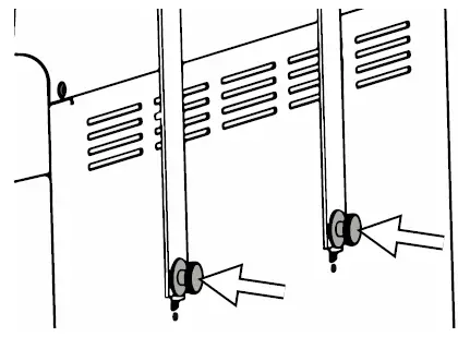
- Remove the device from the box using the carrying straps.
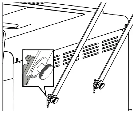
- To remove the straps, loosen the four knurled screws.

- Pull the fastening system out of the device openings.

- Store the carrying straps carefully.
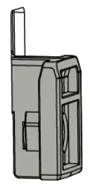
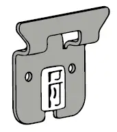
Cover caps or Carebox holders
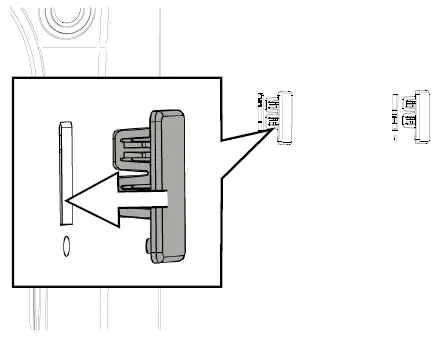
There are rectangular cut-outs on both side panels of the device for attaching the Carebox holders. Alternatively, these can be closed with the cover caps included in the scope of delivery.
Attaching the cover caps
- Press the cover caps into the free recess as shown.

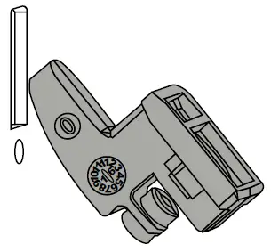
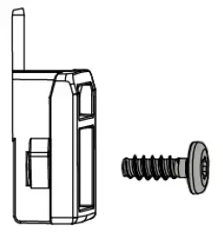
Attaching the holder for the Carebox
PLEASE NOTE
The spacers are intended for installation on the side wall of the device.
- For a room wall installation, the spacers are not used.
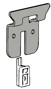
- Insert the fastening hook into the recess at an angle and pointing upwards.

- Pull the fastening hook vertically downwards until it clicks into place.

- Secure the bracket with the short screw provided.

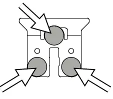
- Glue the three spacers to the back of the bracket.

- Place the bracket over the corresponding recess on the device (moisten the spacers for easier mounting).

- Pull the bracket and the fastening hook vertically downwards until they click into place.

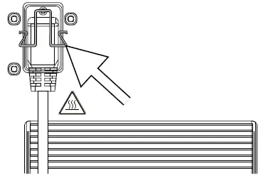
Connecting the power cable and removing accessories
NOTICE
Before switching on for the first time, the device must have acclimatised to the required ambient temperature (5 – 40 °C).
- Connect the power cable to the rear of the device and fold down the safety latch.

- Connect the device power plug to the mains socket.
- Switch on the device at the power switch. The start screen appears on the display.
- After a short waiting time, the Favourites menu is displayed.
PLEASE NOTE
After starting, the device tries to deliver feed water into the tank and into the double jacket. If no feed water is available yet, a malfunction message is displayed. - Use the door mode to avoid the malfunction message.
- After a short waiting time, the Favourites menu is displayed.
- Press the OPEN DOOR button to open the door.
- Remove all accessories from the sterilization chamber.
- Close the door.
- Press the power switch to shut down the machine.
- Remove the mains plug to disconnect the device from the power supply.
Connecting the feed water supply (installation examples)
The following pages provide examples for the recommended installation types for the feed water supply. The connection of a different water treatment unit with the same water quality is possible after consultation with MELAG.
PLEASE NOTE
For detailed information on the cold water connection of the water treatment unit, see the user manual of the unit.
Installation material
The following additional material can be ordered as required:
| Qty. | Article | Art. no. |
| 1 | Compressed air distributor (2-way) | ME80220 |
| 1 | Surface-mounted siphon | ME37410 |
| 1 | Water tap 3/4” with safety combination | ME37310 |
| 1 | Additional water tap with unit combination (for connection to a pre-existing angle valve) | ME58130 |
| 1 | Pressure increase pump for MELAdem 47 | ME22500 |
| 1 | MELAjet spray pistol | ME27300 |
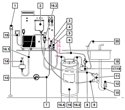
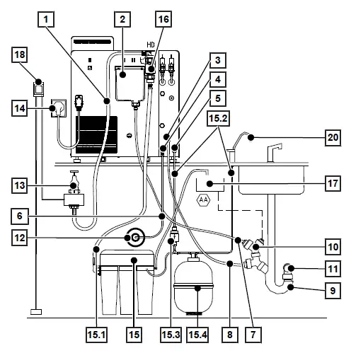
Example 1: Use of the water treatment unit MELAdem 53/53 C (HD)
- Cut the PUR 6/4 mm (5 m) hose for the compressed air supply (4) and the feed water connection (5) into two suitable pieces.
- Connect the water treatment unit MELAdem 53/53 C to the feed water connection (5) of the device either via a water branch (17) or by means of a water distributor (19). Insert the filter for MELAdem (18) in between.
- Fix the safety combination HD (16.3) to the house wall, observing the flow direction indicated on the safety combination. Keep the minimum distance of the drop section under the safety combination.
- Cut the PTFE 8/6 mm (5 m) hose for the overflow funnel (2) and the wastewater connection (3) into two suitable pieces.
- The direct connection of the water treatment unit to the domestic water system requires the installation of the water stop (1).
| Position | Description | Art. no. | contained in |
| 1 | Water stop (leak water detector with cut-off valve and sensor) | ME01056 | — |
| 2 | Overflow funnel | — | present on the device side |
| 3 | Wastewater connection | — | — |
| 3.1 | Threaded connection 1/8” on hose 8/6 mm | ME89120 | present on the device side |
| 4 | Compressed air connection | — | — |
| 4.1 | 2x Cu seal 13.5×18.5 | ME36060 | Installation set |
| 4.2 | Banjo bolt G 1/4″ | — | Installation set |
| 4.3 | QSS-E Swivel | — | Installation set |
| 5 | Feed water connection, water treatment unit | — | — |
| 5.1 | 2x Cu seal 13.5×18.5 | ME36060 | Installation set |
| 5.2 | Banjo bolt G 1/4″ | — | Installation set |
| 5.3 | QSS-E Swivel | — | Installation set |
| 6 | PUR hose (black) 6/4 mm | see above | Installation set |
| 7 | PUR hose (black) 6/4 mm | see above | Installation set |
| 8 | PTFE hose (8/6 mm) | see above | Installation set |
| 9 | PTFE hose (8/6 mm) | see above | Installation set |
| 10 | Double-chamber siphon | ME26635 | Installation set |
| 11 | 2x double hose nozzle for siphon | ME37400 | Installation set |
| 11.1 | 2x Cu seal 13.5×20 | ME32050 | Installation set |
| 11.2 | 2x QSS-E straight | ME38710 | Installation set |
| 11.3 | 2x wastewater adapter G1/4″ internal thread | ME56930 | Installation set |
| 12 | Wall outlet NW40 | — | present on the building side |
| 13 | Compressed air supply | — | present on the building side |
| 13.1 | Coupling plug for compressed air on 6 mm hose | ME80230 | Installation set |
| 14 | Water tap 3/4” with safety combination | ME37310 | — |
| 15 | Mains connection | — | present on the building side |
| 16 | MELAdem 53/53C | ME01038/ ME01036 | — |
| 16.1 | Tap water supply hose EN 1717, 2.5 m | ME24930 ME01038/ ME01036 | |
| 16.2 | Pipe elbow with drain valve | ME70405 | ME01038/ ME01036 |
| 16.3 | Safety combination HD according to EN 1717 for wall mouting | ME70685 | ME01038/ ME01036 |
| 16.4 | Tap water supply hose EN 1717, 0.8 m | ME24932 | ME01038/ ME01036 |
| 17 | Cold water adapter 3/4″ to 1/4″ (direct connection water hose) | ME09037 | Installation set |
| 18 | Filter for MELAdem | ME48240 | — |
| The following additional material can be ordered: | |||
| 19 | Water distributor for MELAdem 53 for connecting several devices | ME69005 | — |
| 20 | External tap for demineralised water | ME91900 | — |
| Hose PUR (black) 6/4 mm (10 m) | ME28820 | — | |
| Hose PTFE (8/6 mm, 5 m, wastewater hose) | ME39180 | — | |
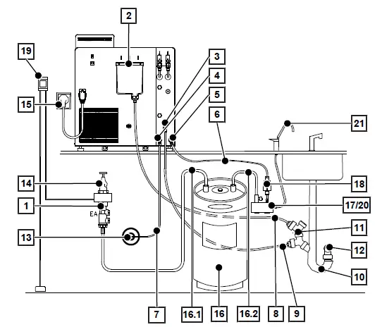
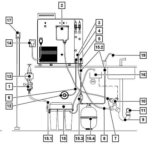
Example 2: Use of the water treatment unit MELAdem 53/53 C (EA)
- Cut the PUR 6/4 mm (5 m) hose for the compressed air supply (4) and the feed water connection (5) into two suitable pieces.
- Connect the water treatment unit MELAdem 53/53 C to the MELAdem feed water connection (5) of the device either via a water branch (17) or by means of a water distributor (20). Insert the filter for MELAdem (18) in between.
- Cut the PTFE 8/6 mm (5 m) hose for the overflow funnel (2) and the wastewater connection (3) into two suitable pieces.
- The direct connection of the water treatment unit to the domestic water system requires the installation of the water stop (19).
| Position | Description | Art. no. | contained in |
| 1 | Return flow inhibitor type EA | ME75300 | — |
| 2 | Overflow funnel | — | present on the device side |
| 3 | Wastewater connection | — | — |
| 3.1 | Threaded connection 1/8” on hose 8/6 mm | ME89120 | present on the device side |
| 4 | Compressed air connection | — | — |
| 4.1 | 2x Cu seal 13.5×18.5 | ME36060 | Installation set |
| 4.2 | Banjo bolt G 1/4″ | — | Installation set |
| 4.3 | QSS-E Swivel | — | Installation set |
| 5 | Feed water connection, water treatment unit | — | — |
| 5.1 | 2x Cu seal 13.5×18.5 | ME36060 | Installation set |
| 5.2 | Banjo bolt G 1/4″ | — | Installation set |
| 5.3 | QSS-E Swivel | — | Installation set |
| 6 | PUR hose (black) 6/4 mm | see above | Installation set |
| 7 | PUR hose (black) 6/4 mm | see above | Installation set |
| 8 | PTFE hose (8/6 mm) | see above | Installation set |
| 9 | PTFE hose (8/6 mm) | see above | Installation set |
| 10 | Double-chamber siphon | ME26635 | Installation set |
| 11 | 2x double hose nozzle for siphon | ME37400 | Installation set |
| 11.1 | 2x Cu seal 13.5×20 | ME32050 | Installation set |
| 11.2 | 2x QSS-E straight | ME38710 | Installation set |
| 11.3 | 2x wastewater adapter G1/4″ internal thread | ME56930 | Installation set |
| 12 | Wall outlet NW40 | — | present on the building side |
| 13 | Compressed air supply | — present on the building side | |
| 13.1 | Coupling plug for compressed air on 6 mm hose | ME80230 | Installation set |
| 14 | Water tap | — | present on the building side |
| 15 | Mains connection | — | present on the building side |
| 16 | MELAdem 53/53C | ME01038/ ME01036 | — |
| 16.1 | Tap water supply hose EN 1717, 2.5 m | ME24930 | ME01038/ ME01036 |
| 16.2 | Pipe elbow with drain valve | ME70405 | ME01038/ ME01036 |
| 16.3 | Safety combination HD according to EN 1717 for wall mouting | ME70685 | ME01038/ ME01036 |
| 17 | Cold water adapter 3/4″ to 1/4″ (direct connection water hose) | ME09037 | Installation set |
| 18 | Filter for MELAdem | ME48240 | — |
| 19 | Water stop (leak water detector with cut-off valve and sensor) | ME01056 | — |
| The following additional material can be ordered: | |||
| 20 | Water distributor for MELAdem 53 for connecting several devices | ME69005 | — |
| 21 | External tap for demineralised water | ME91900 | — |
| Hose PUR (black) 6/4 mm (10 m) | ME28820 | — | |
| Hose PTFE (8/6 mm, 5 m, wastewater hose) | ME39180 | — | |
Example 3: Using the reverse osmosis unit MELAdem 47 (HD)
- Hook the safety combination HD (16) into the fastening next to the overflow funnel (2) and fix it with the screw supplied. Observe the flow direction indicated on the safety combination.
- Shorten the PUR 6/4 mm (5 m) hose for the compressed air supply (4) to the required length.
- Cut the PTFE 8/6 mm (5 m) hose for the overflow funnel (2) and the wastewater connection (3) into two suitable pieces.
- The direct connection of the water treatment unit to the domestic water system requires the installation of the water stop (18).
PLEASE NOTE
If the line pressure is less than 3 bar or if several devices are operated simultaneously, the pressure increase pump for MELAdem 47 must be used.
| Position | Description | Art. no. | contained in |
| 1 | Tap water supply hose EN 1717, 2.5 m | ME24930 | — |
| 2 | Overflow funnel | — | present on the device side |
| 3 | Wastewater connection | — | — |
| 3.1 | Threaded connection 1/8” on hose 8/6 mm | ME89120 | present on the device side |
| 4 | Compressed air connection | — | — |
| 4.1 | 2x Cu seal 13.5×18.5 | ME36060 | Installation set |
| 4.2 | Banjo bolt G 1/4″ | — | Installation set |
| 4.3 | QSS-E Swivel | — | Installation set |
| 5 | Feed water connection, water treatment unit | — | — |
| 5.1 | 2x Cu seal 13.5×18.5 | ME36060 | Installation set |
| 5.2 | Banjo bolt G 1/4″ | — | Installation set |
| 5.3 | QSS-E Swivel | — | Installation set |
| 6 | Hose PUR (black) 6/4 mm | see above | Installation set |
| 7 | PTFE hose (8/6 mm) | see above | Installation set |
| 8 | PTFE hose (8/6 mm) | see above | Installation set |
| 9 | Double-chamber siphon | ME26635 | Installation set |
| 10 | 2x double hose nozzle for siphon | ME37400 | Installation set |
| 10.1 | 2x Cu seal 13.5×20 | ME32050 | Installation set |
| 10.2 | 2x QSS-E straight | ME38710 | Installation set |
| 10.3 | 2x wastewater adapter G1/4″ internal thread | ME56930 | Installation set |
| 11 | Wall outlet NW40 | — | present on the building side |
| 12 | Compressed air supply | — | present on the building side |
| 12.1 | Coupling plug for compressed air on 6 mm hose | ME80230 | Installation set |
| 13 | Water tap 3/4” with safety combination | ME37310 | — |
| 14 | Mains connection | — | present on the building side |
| 15 | MELAdem 47 reverse osmosis unit | ME01047 | — |
| 15.1 | Water inflow hose | ME37220 | ME01047 |
| 15.2 | Hose PUR (black) 6/4 mm (10 m) | ME28820 | ME01047 |
| 15.3 | Filter for MELAdem | ME48240 | ME01047 |
| 15.4 | Pressure tank MELAdem 47 (with shut-off valve and hose) | ME57065 | ME01047 |
| 16 | Safety combination HD | ME82384 | — |
| 17 | Type AA safety device for separation from wastewater disposal in accordance with EN 1717 | — | present on the building side |
| 18 | Water stop (leak water detector with cut-off valve and sensor) | ME01056 | — |
| The following additional material can be ordered: | |||
| 19 | External tap for demineralised water | ME91900 | — |
| Hose PTFE (8/6 mm, 5 m, wastewater hose) | ME39180 | — |
Example 4: Using the reverse osmosis unit MELAdem 47 (EA)
- Shorten the PUR 6/4 mm (5 m) hose for the compressed air supply (4) to the required length.
- Cut the PTFE 8/6 mm (5 m) hose for the overflow funnel (2) and the wastewater connection (3) into two suitable pieces.
- The direct connection of the water treatment unit to the domestic water system requires the installation of the water stop (17).
PLEASE NOTE
If the line pressure is less than 3 bar or if several devices are operated simultaneously, the pressure increase pump for MELAdem 47 must be used.
| Position | Description | Art. no. | contained in |
| 1 | Return flow inhibitor type EA | ME75300 | — |
| 2 | Overflow funnel | — | present on the device side |
| 3 | Wastewater connection | — | — |
| 3.1 | Threaded connection 1/8” on hose 8/6 mm | ME89120 | present on the device side |
| 4 | Compressed air connection | — | — |
| 4.1 | 2x Cu seal 13.5×18.5 | ME36060 | Installation set |
| 4.2 | Banjo bolt G 1/4″ | — | Installation set |
| 4.3 | QSS-E Swivel | — | Installation set |
| 5 | Feed water connection, water treatment unit | — | — |
| 5.1 | 2x Cu seal 13.5×18.5 | ME36060 | Installation set |
| 5.2 | Banjo bolt G 1/4″ | — | Installation set |
| 5.3 | QSS-E Swivel | — | Installation set |
| 6 | PUR hose (black) 6/4 mm | see above | Installation set |
| 7 | PTFE hose (8/6 mm) | see above | Installation set |
| 8 | PTFE hose (8/6 mm) | see above | Installation set |
| 9 | Double-chamber siphon | ME26635 | Installation set |
| 10 | 2x double hose nozzle for siphon | ME37400 | Installation set |
| 10.1 | 2x Cu seal 13.5×20 | ME32050 | Installation set |
| 10.2 | 2x QSS-E straight | ME38710 | Installation set |
| 10.3 | 2x wastewater adapter G1/4″ internal thread | ME56930 | Installation set |
| 11 | Wall outlet NW40 | — | present on the building side |
| 12 | Compressed air supply | — | present on the building side |
| 12.1 | Coupling plug for compressed air on 6 mm hose | ME80230 | Installation set |
| 13 | Water tap | — | present on the building side |
| 14 | Mains connection | — | present on the building side |
| 15 | MELAdem 47 reverse osmosis unit | ME01047 | — |
| 15.1 | Water inflow hose | ME37220 | ME01047 |
| 15.2 | PUR hose (black) 6/4 mm | ME28820 | ME01047 |
| 15.3 | Filter for MELAdem | ME48240 | ME01047 |
| 15.4 | Pressure tank MELAdem 47 (with shut-off valve and hose) | ME57065 | ME01047 |
| 16 | Safety combination HD | ME82384 | — |
| 17 | Type AA safety device for separation from wastewater disposal in accordance with EN 1717 | — | present on the building side |
| 18 | Water stop (leak water detector with cut-off valve and sensor) | ME01056 | — |
| The following additional material can be ordered: | |||
| 19 | External tap for demineralised water | ME91900 | — |
| Hose PUR (black) 6/4 mm (10 m) | ME28820 | — | |
| Hose PTFE (8/6 mm, 5 m, wastewater hose) | ME39180 | — |
Connection to wastewater system
NOTICE
The Careclave connection set must be used for connection to the wastewater system, as other waste water fittings may be made of materials that are not resistant to dental oil.
Since the backflow flap is not resistant to dental oil, the water drainage hose may only be connected to the lowest connection as shown in the following illustration. The backflow flap may only be installed at the points described.
PLEASE NOTE
For safe operation of the device, two drain hoses must be installed between the device and the siphon.
- The siphon must not be more than 2.5 m away from the device.
- For a continuous gradient, the hoses should be kept as short as possible.
- Cut two suitable drain hoses from the supplied PTFE hose.
- Remove the backflow flap from the double hose nozzle (pos. 3) for connecting the wastewater connection.
- Connect the overflow funnel (pos. 1) and the wastewater connection (pos. 3) of the device with separate hoses via the double hose nozzle to a double chamber siphon.
- Perform a drain test by pouring approx. 500 ml into the overflow funnel.
- The drain funnel must be empty within 30 s.
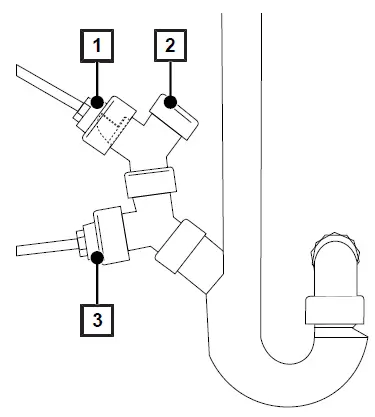
- Drain hose overflow funnel with backflow flap
- Optional wastewater connection for another device or a water treatment unit
- Drain hose without backflow flap
Connection to the compressed air supply
- Assemble the compressed air connection, consisting of the banjo bolt (G 1/4″), SVS-E swivel and two copper seals (13.5×18.5).
- Mount the assembled compressed air connection on the steam sterilizer.
- Shorten the PUR 6/4 hose to the required length.
- Connect the PUR hose to the steam sterilizer.
- Connect the PUR hose with the coupling plug to the compressed air supply on the building side.
Aligning the device
To enable malfunction-free operation, the device must be set up in a horizontal position using a spirit level placed on the chamber flange. Then extend the front device feet by three revolutions to effect a slight rearwards slope of the device.
Setting up the Carebox
- Remove the Carebox from its packaging.
- Replace the pre-installed blind adapters with the required instrument adapters according to the user manual.
- If necessary, replace the supplied Carebox identification plate with an individually labelled version.
Test runs
Carry out the test runs according to the record of installation and setup. Successful test runs are a prerequisite for com-missioning the device.
PLEASE NOTE
To execute the service program Oil dosing venting it is necessary to log on as an administrator or service technician.
Instructing the users
Hand over the manufacturer’s inspection report. The declaration of conformity regarding the pressure equipment direc-tive and the Medical Devices Directive is included in the manufacturer’s inspection report. Conduct a training program for the users and record the details in the training log.
Settings and adjustment
Service connection
PLEASE NOTE
While using the service connection with MELAview, no other activities may be carried out on the device.
The service connection enables the diagnosis of the device and the control of valves via the MELAview 4 Service soft-ware.
Settings on the device
PLEASE NOTE
To define and change settings it is sometimes necessary to log in as an administrator.
Further information can be found in the user manual.
- Date and time
Check the date and time and set if necessary. Consult the user manual. - Display settings
If necessary, adjust the brightness of the display in the Settings > Brightness menu. - Volume
If necessary, adjust the volume in the Settings > Volume menu. - Resetting the maintenance counter
Reset the maintenance counter according to separate instructions (“Reset maintenance counter”, doc: AS_001-21). - User administration and logging
Instruct the user in the user administration and possible logging: see user manual. The Admin PIN can be found in the user manual. - IP addresses
The IP address is automatically obtained by the device via DHCP. If necessary, a static IP can be assigned to the device. - Drying and other program modifications
- The programs of the steam sterilizer correspond in their sequences of fractionating, heating, sterilizing, pressure release, drying and aeration and its parameters pressure, temperature and time to the usual, practice-relevant requirements. For some programs, some options are available by default in the respective program options to influence the program se-quence.
- Changes to the program sequence can be made to the parameters of the Drying, Care and the Carebox detection func-tions.
- Further alterations to the program run are possible in each individual case and will still ensure the effectiveness of the sterilization, but may only be performed by authorized persons. Please consult your stockist or MELAG.
- System and status log
Output a system and status log and document this on the record of installation and setup. - Counter status and measured values
You have the option of calling up counter status and other current technical data of the steam sterilizer via the Device status > Counters and measurements button.
Technical tables
Feed water quality
Minimum requirements to the feed water following EN 13060, Appendix C
| Substance/property | Feed water |
| Evaporation residue | ≤ 10 mg/l |
| Silicon oxide, SiO2 | ≤ 1 mg/l |
| Iron | ≤ 0.2 mg/l |
| Cadmium | ≤ 0.005 mg/l |
| Lead | ≤ 0.05 mg/l |
| Traces of heavy metal apart from iron, cadmium, lead | ≤ 0.1 mg/l |
| Chloride | ≤ 2 mg/l |
| Phosphate | ≤ 0.5 mg/l |
| pH value | 5 – 7.5 |
| Appearance | ≤ colourless, clear, without sediments |
| Hardness | ≤ 0.02 mmol/l |
Precision and drift behaviour
Sensors
Temperature sensors
| Sensor type | PT 1000 Class A according to DIN EN 60751 |
| Precision (at 135 °C) | ± 0.42 K |
| Drift per year | ± 0.05 K |
| Drift in 5 years | ± 0.25 K |
Pressure sensor
| Sensor type | Piezoresistant absolute pressure sensor 0 to 4000 mbar |
| Precision | ± 0.3 % corresponds to ± 12 mbar corresponds to approx. ± 0.13 K steam |
| Drift per year | ± 0.2 % corresponds to ± 8 mbar corresponds to approx. ± 0.09 K steam |
| Drift in 5 years | ± 1.0 % corresponds to ± 40 mbar corresponds to approx. ± 0.44 K steam |
Drift behaviour of the circulation pressure sensor and the circulation temperature sensor
Measuring chains
Measuring chain for the temperature measurement on the electronics (without sensor)
| Precision (at 135 °C) | ± 0.2 K |
| Drift per year | ± 0.005 K |
| Drift in 5 years | ± 0.025 K |
Measuring chain for the pressure measurement on the electronics (without sensor)
| Precision | ± 0.2 % corresponds to ± 8.0 mbar corresponds to approx. ± 0.09 K steam |
| Drift per year | ± 0.004 % corresponds to ± 0.16 mbar corresponds to approx. ± 0.017 K steam |
| Drift in 5 years | ± 0.02 % corresponds to ± 0.8 mbar corresponds to approx. ± 0.09 K steam |
After 1 year
Entire measuring chain of the temperature measurement
| Precision (at 135 °C) | at pure addition of individual errors approx. ± 0.70 K |
| Precision (at 135 °C) | according to Gauss’ law of propagation approx. ± 0.47 K |
Entire measuring chain of the pressure measurement
| Precision | at pure addition of indiv. errors | ± 0.70 % corresponds to ± 28.0 mbar corresponds to approx. ± 0.30 K steam temperature |
| Precision | per Gauss’ law of propagation | ± 0.41 % corresponds to ± 16.5 mbar corresponds to approx. ± 0.18 K steam temperature |
After 5 year
Entire measuring chain of the temperature measurement
| Precision (at 135 °C) | at pure addition of individual errors approx. ± 0.70 K |
| Precision (at 135 °C) | according to Gauss’ law of propagation approx. ± 0.47 K |
Entire measuring chain of the pressure measurement
| Precision | at pure addition of individual errors | ± 0.70 % corresponds to ± 28.0 mbar corresponds to approx. ± 0.30 K steam temperature |
| Precision | per Gauss’ law of propagation | ± 0.41 % corresponds to ± 16.5 mbar corresponds to approx. ± 0.18 K steam temperature |
Nominal value tolerances
| Step | P [mbara] | T [°C] | Care-S and. Care-B | Care- Therm | Univer- sal-B | Gentle-B | Quick-S | Program phase | |
| Tolerance P / T | |||||||||
| SP-S | — | — | — | — | — | — | — | Program start | |
| CP1 | — | — | — | — | — | — | — | Carebox detection | |
| KU1 | w 3000 | — | +2000/ -200 | ◄ | x | x | x | Exterior cleaning | |
| ZU1 | w 3000 | — | +2000/ -200 | ◄ | x | x | x | Exterior cleaning | |
| WU1 | w 3000 | w 55 | P: +2000/ -200 and T≥ 55 °C | ◄ | x | x | x | Exterior cleaning – warm | |
| DH1 | — | A0 3000 | x | min. A0 3000 | x | x | x | Disinfection heating | *) |
| P1 | — | — | — | — | x | x | x | Nursing process | |
| P2 | — | — | — | — | x | x | x | Nursing process | |
| SV1 | c 500 | — | +30/-30 | x | x | x | x | Pre-evacuation | |
| SK11 | c 525 | — | +100/-20 | x | x | x | x | Steam entry drive channels | |
| SK12 | c 550 | — | +100/-20 | x | x | x | x | Steam inlet spray channels | |
| Step | P [mbara] | T [°C] | Care-S and. Care-B | Care- Therm | Univer- sal-B | Gentle-B | Quick-S | Program phase | |
| Tolerance P / T | |||||||||
| SK13 | c 1500 | — | +100/-20 | x | x | x | x | Steam intake sterilization chamber | |
| SH1 | c 1500 | — | +100/ -100 | x | x | x | x | Holding conditioning | |
| SF2 | c 500 | — | +30/-30 | x | x | x | x | Fractionation evacuation | |
| SK21 | c 525 | — | +100/-20 | x | x | x | x | Steam entry drive channels | |
| SK22 | c 550 | — | +100/-20 | x | x | x | x | Steam inlet spray channels | |
| SK11 | c 1900 | — | x | x | +100/-20 | c 1800 ● | c 1800 ● | Conditioning steam intake |
**) |
| SK12 | c 1900 | — | x | x | +100/ -500 | c 1800 ● | ● | Holding conditioning | |
| SK13 | c 1300 | — | x | x | +20/-50 | ● | ● | Conditioning pressure release | |
| SF12 | c 300 | — | x | x | +30/-30 | ● | c 225 ● | Fractionation evacuation | |
| SF13 | c 2100 | — | x | x | +100/-20 | c 1800 ● | ● | Fractionation steam intake | |
| SF21 | c 1300 | — | x | x | +20/-50 | ● | ● | Fractionation pressure release | |
| SF22 | c 200 | — | x | x | +30/-30 | ● | c 150 ● | Fractionation evacuation | |
| SF23 | c 2100 | — | x | x | +100/-20 | c 1800 ● | x | Fractionation steam intake | |
| SF31 | c 1300 | — | x | x | +20/-50 | ● | x | Fractionation pressure release | |
| SF32 | c 500 | — | x | x | +30/-30 | ● | x | Fractionation evacuation | |
| SF33 | c 2000 | — | x | x | +100/-20 | c 1500 ◄ | ◄ | Fractionation steam intake | |
| SH1 | c 2950 | — | +60/-60 | x | ◄ | c 1850 ◄ | ◄ | Holding steam intake | |
| SH2 | c 2950 | — | +60/-60 | x | ◄ | c 1950 ◄ | ◄ | Holding control | |
| SS1 | c 3031 | c 134 | +60/-60 | x | ◄ | c 2080 ◄ | ◄ | Sterilization entry | |
| SS2 | c 3170 | c 135.3 | +60/-60 | x | ◄ | c 2150 ◄ | ◄ | Sterilization | |
| SA1 | c 3000 | — | +20/-50 | x | x | x | x | Pressure release Carebox | |
| SA2 | c 1943 | — | +20/-50 | x | 1300 | ◄ | ◄ | Pressure release | |
| TVA | c 190 | — | — | ◄ | ◄ | x | x | Drying evacuation | |
| TDL | c 741 | — | — ◄ | ◄ | x | x | Compressed air drying | ||
| ST12 | c 80 | — | x | x | — | — | — | Holding drying |
**) |
| ST13 | c 180 | — | x | x | — | — | — | Drying ventilation | |
| ST21 | c 80 | — | x | x | — | — | — | Drying evacuation | |
| ST22 | c 80 | — | x | x | — | — | — | Holding drying | |
| ST23 | c 180 | — | x | x | — | — | — | Drying ventilation | |
| ST31 | c 80 | — | x | x | — | — | — | Drying evacuation | |
| ST32 | c 80 | — | x | x | — | — | — | Holding drying | |
| SB12 | c ***) | — | — | — | — | — | — | Ventilation | |
| SP-E | — | — | Value | ◄ | ◄ | ◄ | ◄ | Program end | |
Key:
- only Care-Therm
- only Universal-B
- as in the Universal-B — not specified
- Ambient pressure
 as in Care-S x not applicable
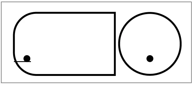
Empty chamber test
The coldest point in the sterilization chamber during the empty chamber test lies directly on the temperature sensor (see circular marking in the following figure). The temperature in the rest of the sterilization chamber is almost the same all over (0.6 K range).
Schematic side and fore view of the sterilization chamber
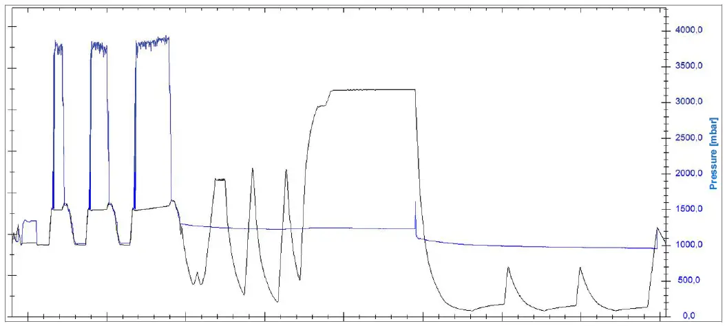
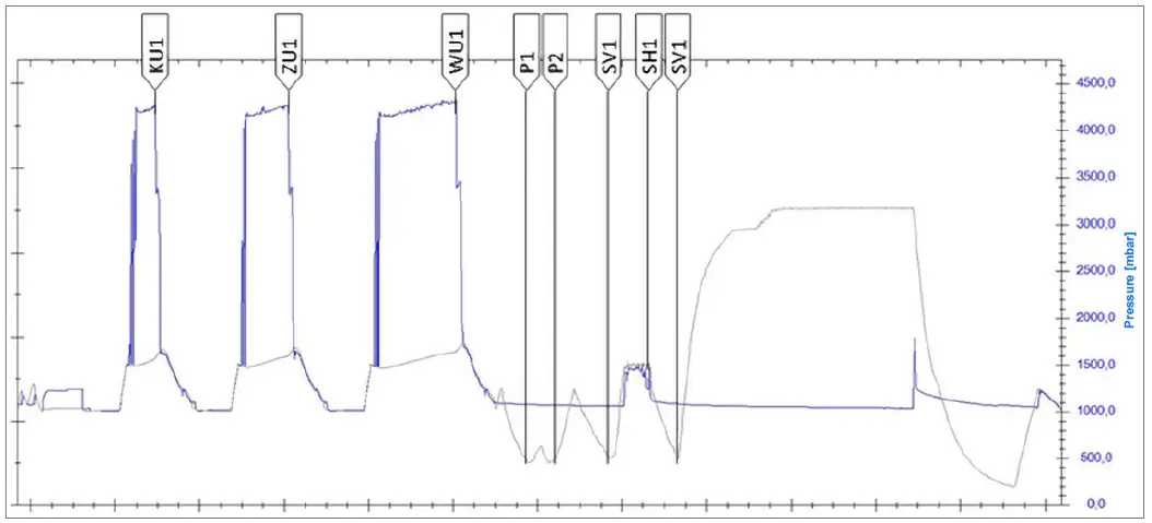
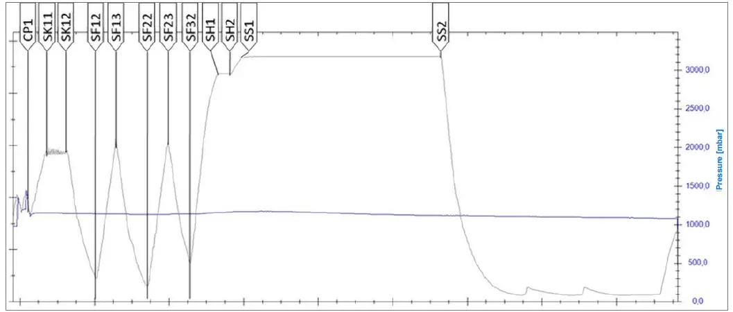
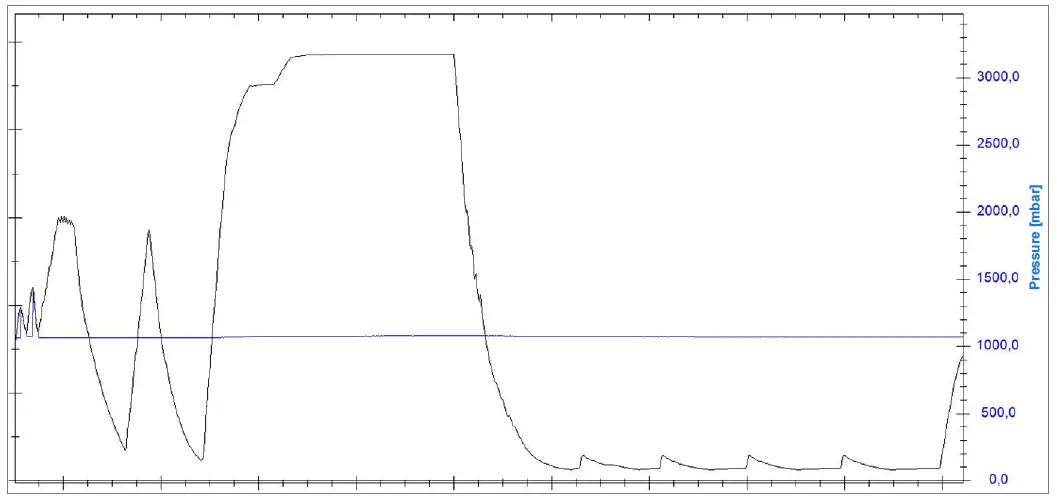
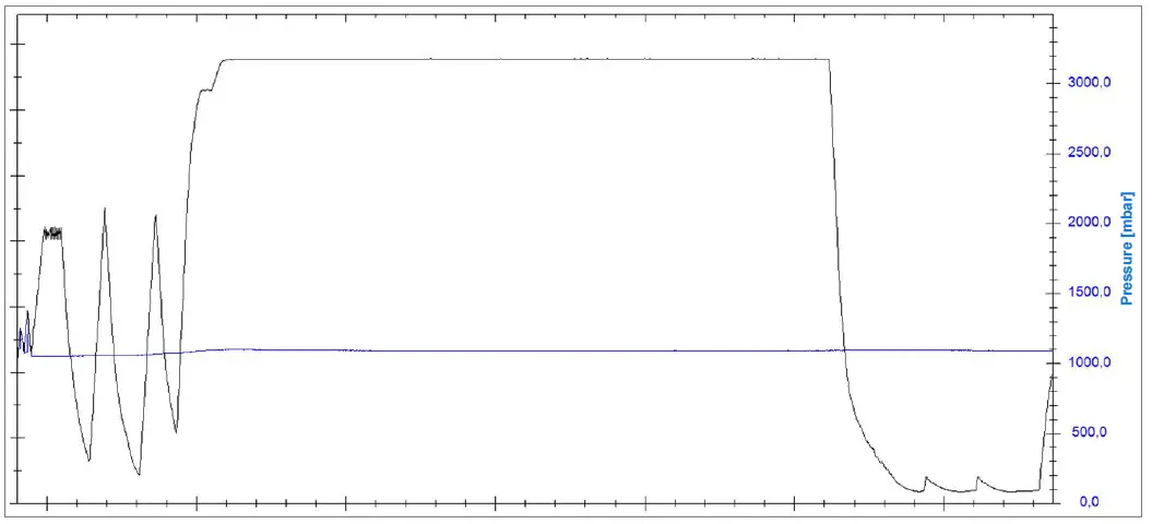
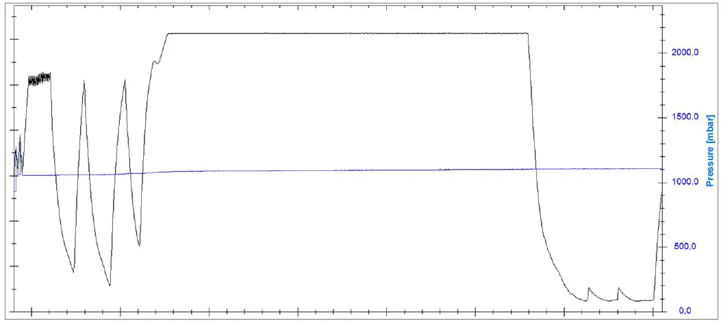
Pressure-time chart
Pressure-time diagram for Care-Therm, A0 > 3000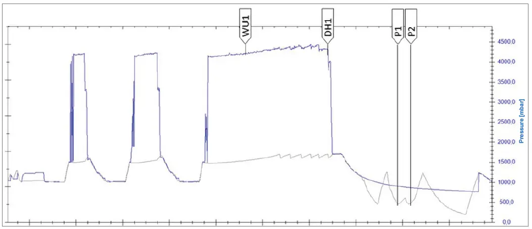
Pressure-time diagram for Care-B
Pressure-time diagram for Care-S, 134°C and 2.1 bar
Pressure-time diagram for Universal-B, 134°C and 2.1 bar
Pressure-time diagram for Quick-S
Pressure-time diagram for Prion-B
Pressure-time diagram for Gentle-B
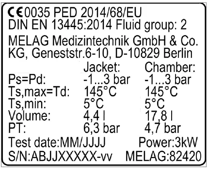
Type plate steam generator
Certificate of Suitability
According to the recommendations of the Commission for Hospital Hygiene and Infection Prevention at the Robert Koch Institute
- Manufacturer: MELAG Medizintechnik GmbH & Co. KG
- Address: Geneststraße 6-10 10829 Berlin
- Country: Germany
- Product: Careclave® 618
- Type of device: Combination steam sterilizers (steam sterilizer with washer-disinfector functionality)
- Classification: Class IIb
- Device type acc. to EN 13060: Type B
We herewith declare that the above designated product is suited for sterilization of
- Solid instruments (wrapped and unwrapped)
- Porous goods (wrapped and unwrapped)
- Products with narrow lumen (wrapped and unwrapped)
- Simple hollow items (wrapped and unwrapped)
Instructions on load quantities and loading variants are specified in the user manual and must be observed. Be sure to observe the manufacturer’s instructions for medical devices intended for sterilization according to EN ISO 17664.
We herewith declare that the following test system is suited for testing the above cited steam sterilizer.
- Helix-Test body according to EN 867-5: MELAcontrol® Helix and MELAcontrol® Pro
In addition, the Careclave is intended for the reprocessing of dental transfer instruments and hollow bodies classified as semi-critical, which are connected in the Carebox:
- Handpieces
- Contra-angles
- Turbines
- Ultrasonic and air scaler tips
The internal and external cleaning as well as the subsequent thermal disinfection comply with the specifications of EN ISO 15883-1 and -2. Optionally, automatic lubrication with care oil can also be carried out.
Berlin, 01.10.2021

MELAG Medizintechnik GmbH & Co. KG
- Geneststraße 6-10 10829 Berlin Germany
- Email: [email protected]
- Web: www.melag.com
- Original instructions
- Responsible for content: MELAG Medizintechnik GmbH & Co. KG We reserve the right to technical alterations.


