![]() XPSUDN Preventa p3Ap Safety Module
XPSUDN Preventa p3Ap Safety Module
Instruction Manual
Preventa XPSUDN p 3Ap
Safety Module
www.schneider-electric.com
![]()
![]() DANGER
DANGER
HAZARD OF ELECTRIC SHOCK, EXPLOSION OR ARC FLASH
- Disconnect all power from all equipment including connected devices prior to removing any covers or doors, or installing or removing any accessories, hardware, cables, or wires except under the specific conditions specified in the appropriate hardware guide for this equipment.
- Always use a properly rated voltage sensing device to confirm the power is off where and when indicated.
- Where 24 Vdc or Vac is indicated, use PELV power supplies conforming to IEC 60204-1.
- Replace and secure all covers, accessories, hardware, cables, and wires and confirm that a proper ground connection exists before applying power to this equipment.
- Use only the specified voltage when operating this equipment and any associated products.
Failure to follow these instructions will result in death or serious injury.![]() DANGER
DANGER
POTENTIAL FOR EXPLOSION
Install and use this equipment in non-hazardous locations only.
Failure to follow these instructions will result in death or serious injury.![]() WARNING
WARNING
INSUFFICIENT AND/OR INEFFECTIVE SAFETY-RELATED FUNCTIONS
- Verify that a risk assessment as per ISO 12100 and/or other equivalent assessment has been performed before this product is used.
- Fully read and understand all pertinent manuals before performing any type of work on or with this product.
- Verify that modifications do not compromise or reduce the Safety Integrity Level (SIL), Performance Level (PL) and/or any other safety-related requirements and capabilities defined for your machine/process.
- After modifications of any type whatsoever, restart the machine/process and verify the correct operation and effectiveness of all functions by performing comprehensive tests for all operating states, the defined safe state, and all potential error situations.
Failure to follow these instructions can result in death, serious injury, or equipment damage.
Electrical equipment should be installed, operated, serviced, and maintained only by qualified personnel.
No responsibility is assumed by Schneider Electric for any consequences arising out of the use of this material.
Preventa XPSUDNp . 3Ap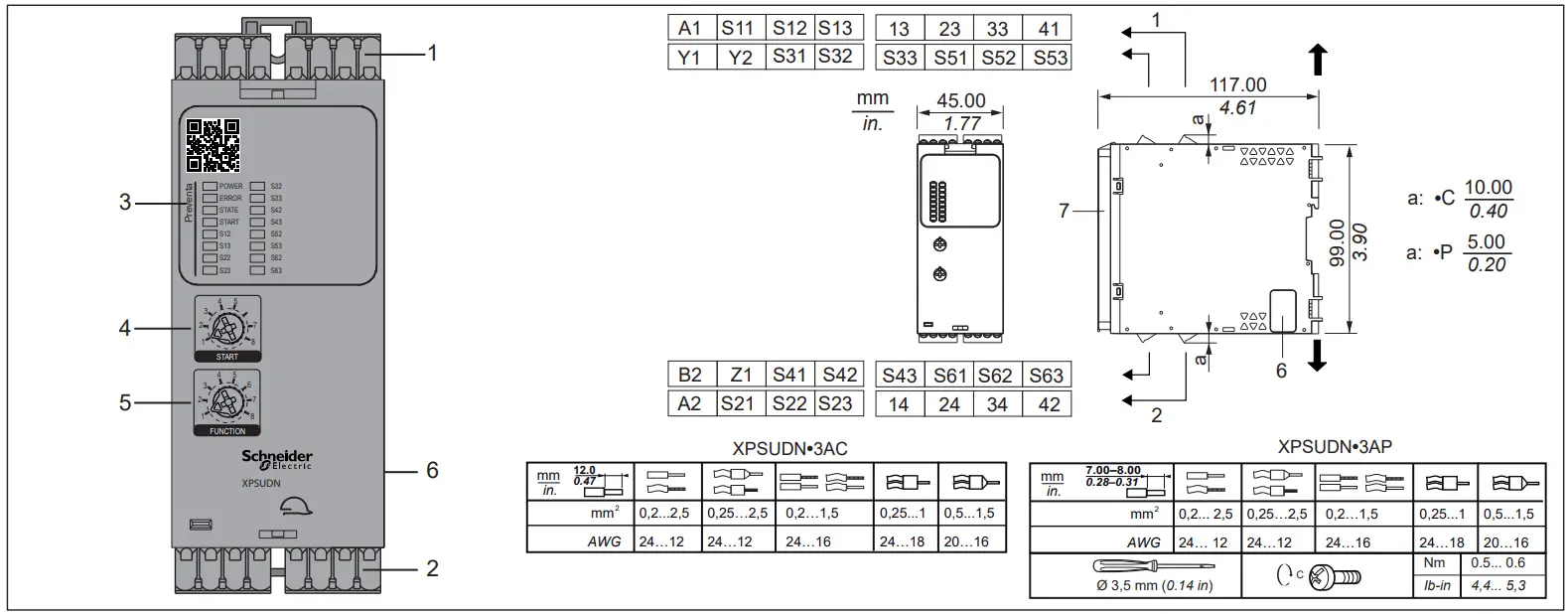
Device Overview
- Removable terminal blocks, top
- Removable terminal blocks, bottom
- LED indicators
- Start function selector
- Function selector
- Connector for optional output extension module (lateral)
- Sealable transparent cover
| Types | ||
| XPSUDN13AC | Supply voltage | terminal type | 24 Vac/Vdc | C |
| XPSUDN13AP | Supply voltage | terminal type | 24 Vac/Vdc | P |
| XPSUDN33AC | Supply voltage | terminal type | 48 … 240 Vac/Vdc | C |
| XPSUDN33AP | Supply voltage | terminal type | 48 … 240 Vac/Vdc | P |
| C = Spring terminals, P = Screw terminals Other characteristics identical for product types listed |
Functions
Function selector (5)
| A | B | C | D | E | F | G | H |
| 1 | NC, NO, C/O | 6(1) | S11–S12 / S21–S22 | A S11–S13 / S21–S23 | B S31–S32 / S41–S42 | C S31–S33 / S41–S43 | D S51–S52 / S61–S62 | E S51–S53 / S61–S63 | F | – | Y | N | |
| 2 | NC, NO, C/O | 6(1) | S11–S12 / S21–S22 | A S11–S13 / S21–S23 | B S31–S32 / S41–S42 | C S31–S33 / S41–S43 | D S51–S52 / S61–S62 | E S51–S53 / S61–S63 | F | 2 / 4 | Y | N | |
| 3 | NC, NO, C/O | 6(2) | S11–S12 / S13, S21–S22 / S23, S31–S32 / S33, S41–S42 / S43, S51–S52 / S53, S61–S62 / S63 | 0.5 | Y | N | |
| 4 | NC, NO, C/O | 6(2) | S11–S12 / S13, S21–S22 / S23, S31–S32 / S33, S41–S42 / S43, S51–S52 / S53, S61–S62 / S63 | 2.2 | Y | N | |
| 5 | PNP | PNP | 6(3) | S12 / S13, S22 / S23, S32 / S33, S42 / S43, S52 / S53, S62 / S63 | – | N | N |
| 6 | PNP | PNP | 6(3) | S12 / S13, S22 / S23, S32 / S33, S42 / S43, S52 / S53, S62 / S63 | 0.5 | N | N |
| 7 | OSSD | 6(3) | S12 / S13, S22 / S23, S32 / S33, S42 / S43, S52 / S53, S62 / S63 | – | N | Y | |
| 8 | OSSD | 6(3) | S12 / S13, S22 / S23, S32 / S33, S42 / S43, S52 / S53, S62 / S63 | 0.5 | N | Y |
- If less than 6 safety-related inputs are used, the unused terminals must be bridged as if a sensor is connected (example: device/sensor F not connected: S51 and S53 / S61 and S63 bridged)
- If less than 6 safety-related inputs are used, the terminals Sn1 and Sn3 must be bridged.
- If less than 6 safety-related inputs are used, terminals Sn1 must be briged with terminals Sn2 and Sn3.
Explanation of table
| A | Position of function selector (5) |
| B | Typical applications |
| C | Output type of device/sensor providing signal |
| D | Number of safety-related inputs used |
| E | Snn terminals to be connected |
| F | Synchronization time in s. If the two synchronized channels or inputs are not activated within this time, the safety-related output(s) is/are not activated. |
| G | Dynamization [Y = Yes | N = No]. Dynamization helps to detect cross circuits between two safety-related inputs or between one safety-related input and the Start input or to an external power supply unit. |
| H | Debounce filter active [Y=Yes I N=No] |
| Monitoring of Emergency Stop Circuit Stop Category 0 ISO 13850 IEC 60204-1 | |
| Monitoring of switches (for example, guard door) ISO 14119/14120 | |
| Monitoring of coded magnetic switches ISO 14119/14120 | |
| Monitoring of type 4 light curtains IEC 61496-1 | |
| NC | Normally closed contact |
| NO | Normally open contact |
| C/O | Changeover contact |
| PNP | Positive negative positive transistor |
| OSSD | Output Signal Switching Device |
![]() WARNING
WARNING
UNINTENDED EQUIPMENT OPERATION
- Do not use the Start function for safety-related purposes.
- If unintended restart is a hazard according to your risk assessment, use Monitored Start or Startup Test.
Failure to follow these instructions can result in death, serious injury, or equipment damage.
Start Function Selector (4)
| 1 | Manual/automatic start(1), no startup test(3), dynamization |
| 2 | Manual/automatic start(1), startup test(3), dynamization |
| 3 | Monitored start(2), no startup test(3), dynamization |
| 4 | Monitored start(2), startup test(3), dynamization |
| 5 | Manual/automatic start(1), no startup test(3), no dynamization |
| 6 | Manual/automatic start(1), startup test(3), no dynamization |
| 7 | Monitored start(2), no startup test(3), no dynamization |
| 8 | Monitored start(2), startup test(3), no dynamization |
| (1) Depends on device/sensor connected to Start input. (2) Falling edge. The safety-related inputs must be activated for a period of at least 80 ms. (3) Startup test: for example, open and close Guard. |
NOTE:
Perform a power cycle after changing the positions of selectors 4, or 5.
Block Diagram
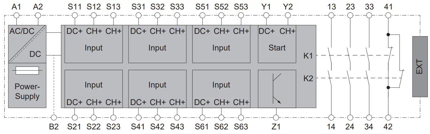
| EXT | Connector for optional extension module |
| B2 | Common ground terminal |
| Z1 | Pulsed output for diagnostics, not safety-related |
Wiring Examples
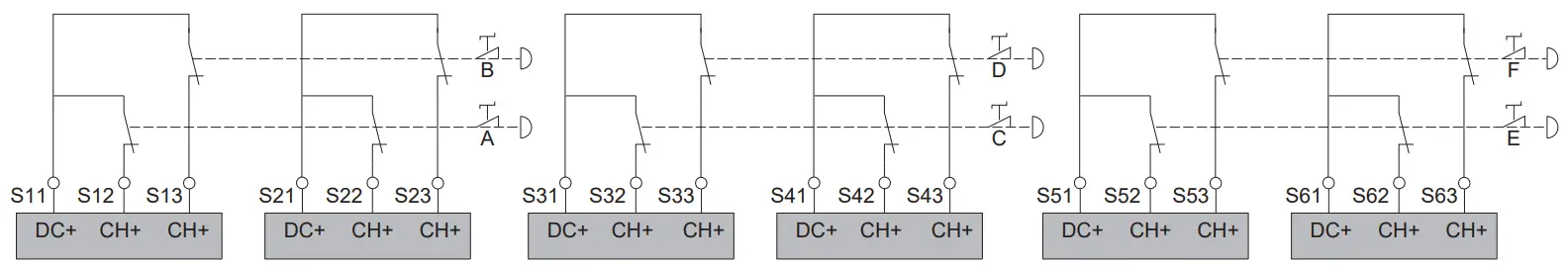
Monitoring of up to 6 Emergency Stop circuits (identical wiring for monitoring of electrical switches, guard door) Function selector positions 1 / 2 (1)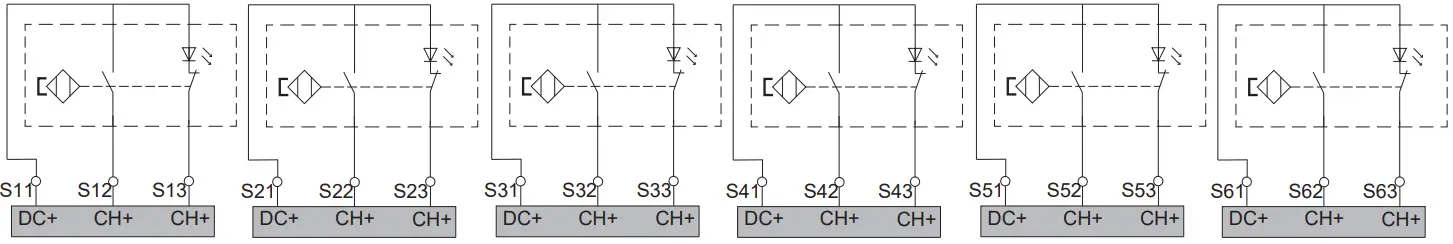
Monitoring of up to 6 coded magnetic switches
Function selector position 3 / 4 (2) 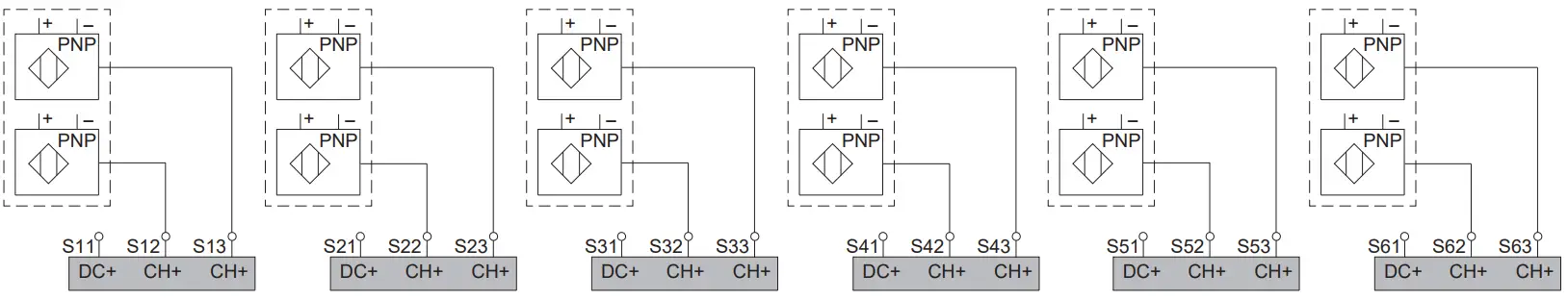
Monitoring of up to 6 x 2 PNPs
Function selector positions 5 / 6(3)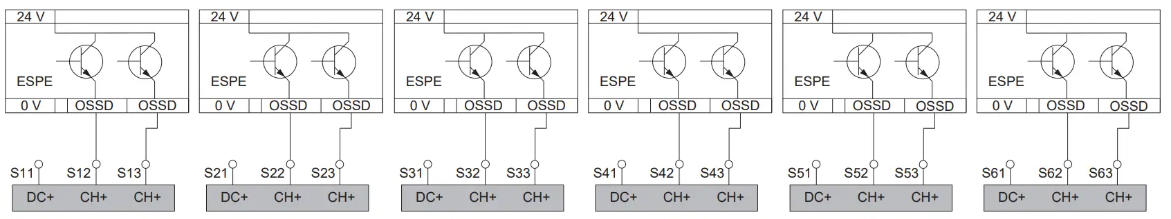
Monitoring of up to 6 type 4 light curtains
Function selector positions 7 / 8 (3)
- If less than 6 safety-related inputs are used, the unused terminals must be bridged as if a sensor is connected (example: device/sensor F not connected: S51 and S53 / S61 and S63 bridged)
- If less than 6 safety-related inputs are used, the terminals Sn1 and Sn3 must be bridged.
- If less than 6 safety-related inputs are used, terminals Sn1 must be briged with terminals Sn2 and Sn3.
Mounting
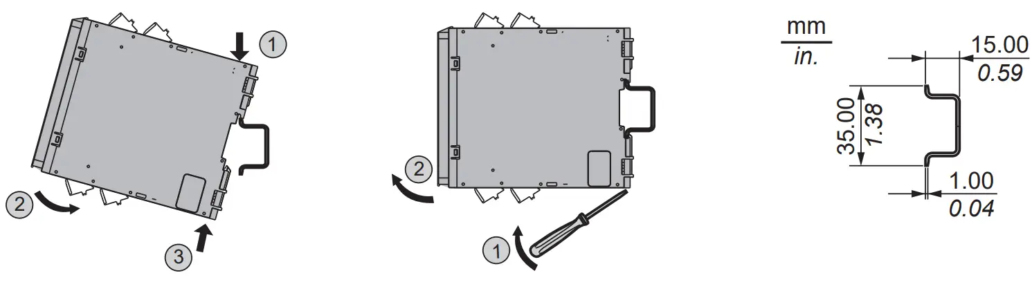
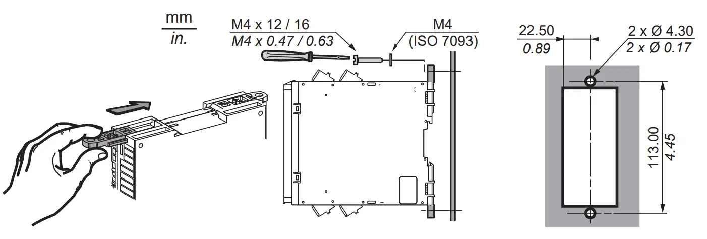
Left: Mounting to DIN rail Right: Screw-mounti
LED | State | Explanation |
| POWER | Power supply on | |
| No power supply | ||
| Snn | Safety-related input activated | |
| Safety-related input deactivated | ||
| START | Valid start condition | |
| No valid start condition | ||
| Waiting for valid start condition | ||
| STATEn ERROR Snn(1) Snn(1) | Normally open safety-related outputs activated | |
| Normally open safety-related outputs deactivated | ||
| Synchronization time alert Other LEDs retain normal behavior | ||
| ERROR Snn(2) Snn(2) | Interlock alert Other LEDs retain normal behavior | |
| ERROR LEDs(3) | General error detected Module in defined safe state | |
| ERROR LEDs(3) | Configuration error detected | |
| ERROR POWER | Power supply error detected | |
| ERROR Snn(2) Snn(2) | Cross circuit detected at safety-related input | |
| ERROR START | Cross circuit detected at Start input | |
| ERROR STATE | Error detected at safety-related output | |
| ERROR START STATE | Error detected at safety-related output of extension module | |
| LEDs | All LEDs light up during power-up for diagnostics purposes. | |
| LED solid on | ||
| LED off | ||
| LED flashing | ||
| (1)Snn | n = number of LED of affected input, LEDs flashing alternatingly | |
| (2)Snn | n = number of LED of affected input, LEDs flashing synchronously | |
| (3)LEDs | All LEDs except POWER |
Technical Data
| Data Functional Safety | |
| Defined safe state: Safety-related outputs are de-energized, NC closed, NO open. | – |
| Maximum Performance Level (PL) Category (cat.) (1) | PL e, cat. 4 (ISO 13849-1:2015) |
| Maximum Safety Integrity Level NO | NC (SIL) (1) | 3 | 1 (IEC 61508-1:2010) |
| Safety Integrity Level Claim Limit NO | NC (SILCL) (1) | 3 | 1 (IEC 62061:2005+ AMD1:2012+ AMD2:2015) |
| (1) Actual values depend on wiring and configuration | – |
| (2) High as per ISO 13849-1 | – |
| Type | B (IEC 61508-2) |
| Hardware Fault Tolerance (HFT) | 1 (IEC 61508, IEC 62061) |
| Stop Category for Emergency Stops | 0 (ISO 13850, IEC 60204-1) |
| Lifetime in years at an ambient temperature of 55 °C (131 °F) | 20 |
| Safe Failure Fraction (SFF), percent | > 99 % (IEC 61508, IEC 62061) |
| Probability of Dangerous Failure per hour (PFHD) [1/h][XPSUDN13A | XPSUDN33A] | 0.88E-09 | 1.36E-09 (IEC 61508, ISO 13849-1) |
| Mean Time To Dangerous Failure (MTTF ) in years(2) | > 30 (ISO 13849-1) |
| Average Diagnostic Coverage (DCavg) (2) | ≥ 99 % (ISO 13849-1) |
| (1) Actual values depend on wiring and configuration | – |
| (2) High as per ISO 13849-1 | – |
Maximum number of cycles over lifetime NO
DC13 24 Vdc 1 A
1200000
| Mechanical Data | |
| Dimensions W x H x D | 45 mm (1.77 in) x 99 mm (3.90 in) x 117 mm (4.61 in) |
| Weight | 0.35 kg (0.77 lbs) |
| Electrical Data | |
| Supply voltage XPSUDN13A• XPSUDN33A• | 24 Vac (-15 % … +10 %) 24 Vdc (-20 % …+20 %) 48 … 240 Vac (-10 % …+10 %) 48 … 240 Vdc (-10 % …+10 %) |
| Nominal input power 24 Vac | 24 Vdc 240 Vac | 48 Vdc | 10.5 VA I 4.5 W 25.0 VA I 6.0 W |
| Frequency range AC | 50 … 60 Hz |
| Overvoltage category | II |
| Pollution degree | 2 |
| Insulation voltage | 300 V |
| Impulse withstand voltage | 4 kV |
NOTE:
All power supplies of all connected equipment must have a common reference potential (terminal B2).
Technical Data Safety-Related Inputs (Snn)
| Number of inputs, positive supplied (1 control output DC+ (Sn1) and 2 inputs CH+ (Sn2–Sn3)), dual-channel | 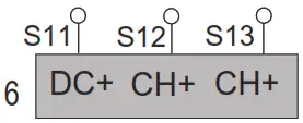 |
| Minimum output voltage at DC+ | DC- | > 15 Vdc |
| Input voltage at CH+ | CH | 0 … 24 Vdc +20 % |
| Switching voltage activate | >15 Vdc |
| Switching voltage deactivate CH+ | <5 Vdc |
| Maximum wire resistance | 60 Ω |
| Debounce filter time constant (standard | with OSSD) | 2.5 | 4 ms |
| Dynamization (test pulse) on control output (Sn1 and Y1): Test pulse duration (safety-related input must be activated longer than test pulse duration) Test pulse interval Test pulse maximum delay Test pulse phase shift | 2 ms 1000 ms 40 ms 70 ms |
| Synchronization times 1 | 2 between inputs (function 2): Rising edge S12 and S22, S13 and S23, S32 and S42, S33 and S43, S52 and S62, S53 and S63 | 2 s I 4 s |
| Synchronization times 1 | 2 between inputs (functions 6, 8): Rising edge S12 and S13, S22 and S23, S32 and S33, S42 and S43, S52 and S53, S62 and S63 | 0.5 s |
| Synchronization time between inputs (functions 3 | 4): Falling edge and rising edge S12 and S13, S22 and S23, S32 and S33, S42 and S43, S52 and S53, S62 and S63, regardless of sequence | 0.5 s | 2.2 |
Technical Data Start Inputs (Y1, Y2)
| Output voltage at DC+ | > 15 Vdc |
| Maximum wire resistance | 60 Ω |
| Technical Data Safety-Related Outputs | |
| Normally Open relay contacts (instantaneous) | 3 |
| Normally Closed relay contacts (instantaneous)) | 1 |
| Maximum short circuit current IK | 1 kA |
| Maximum continuous current NO | NC | 6 A | 3 A |
| Minimum current | 0.01 A |
| Utilization category as per IEC 60947-4-1, IEC 60947-5-1 | AC1 (250 V) | AC15 (250 V) | DC1 (24 V) | DC13 (24 V) |
| Maximum current NO AC1 | AC15 | DC1 | DC13 | 5 A | 3 A | 5 A | 3 A |
| Maximum current NC AC1 | AC15 | DC1 | DC13 | 3 A | 1 A | 3 A | 1 A |
| External fusing [category gG fuse NO | category gG fuse NC] | 10 A | 4 A |
NOTE:
The optional extension module XPSUEP•x4A• provides further safety-related outputs.
Do not remove the label from the extension module connector unless you want to connect the extension module.
Remove all power before connecting the extension module.![]() WARNING
WARNING
INCORRECT USE OF OUTPUTS
Do not use the additional outputs for safety-related purposes.
Failure to follow these instructions can result in death, serious injury, or equipment damage.
Technical Data Additional Output (Z1), Non-Safety-Related
| Semiconductor pulsed output, non-safety-related. Provides diagnostics pattern. | 1 |
| Output voltage | 24 Vdc |
| Maximum current | 20 mA |
Timing Data
| Switch on delay after power on and automatic start | 100 ms |
| Delay after activation of safety-related input or valid start condition | 3000 ms |
| Maximum response time to request at safety-related input | 20 ms |
| Maximum response time after power outage XPSUDN13A• [dc | ac] XPSUDN33A• [dc | ac] | 140 ms | 200 ms 100 ms | 100 ms |
| Recovery time after request at safety-related input | 200 ms |
| Minimum duration of start pulse for monitored start | 80 ms |
Environmental Characteristics
| Storage | IEC 60721-3-1 |
| Ambient temperature | -40 °C … 70 °C (-40 °F … 158 °F), 1K5 |
| Temperature variation | 1 °C/min (1.8 °F/min), 1K5 |
| Ambient humidity | 10 … 100 % r.h, 1K5 |
| Vibration and shock | 1M2 |
| TransportationI…………………………………………………………………………………………………………………………………EC 60721-3-2 | |
| Ambient temperature | -25 °C … 85 °C (-13 °F … 185 °F), 2K5H |
| Temperature variation air/air | -25 °C … 30 °C (-13 °F … 86 °F), 2K5H |
| Ambient humidity, no condensation | 5 … 95 % r.h, 2K5H |
| Vibration and shock | 2M2 |
| Operation………………………………………………………………………………………………………………………………..IEC 60721-3-3 | |
| Ambient temperature, no icing (1) | -25 °C … 55 °C (-13 °F … 131 °F), 3K5, 3Z11 |
| Maximum installation altitude above mean sea level | 2000 m (6562 ft) |
| Temperature variation | 0.5 °C/min (0.9 °F/min), 3K5 |
| Ambient humidity, no condensation | 5 … 95 % r.h, 3K5 |
| Vibration and shock | 3M4 |
| (1) -25 °C … 50 °C (-13 °F … 122°F) with 24 Vac supply voltage. | – |
| Degree of Protection | |
| Housing | IP 40 |
| Terminals | IP 20 |
| Installation required in control cabinet/enclosure with degree of protection | IP 54 |
| Part Name | – Hazardous Substances | |||||
| (Pb) | (Hg) | (Cd) | (Cr (VI)) | (PBB) | (PBDE) | |
| Metal parts | 0 | 0 | 0 | 0 | 0 | 0 |
| Plastic parts | o | 0 | 0 | 0 | 0 | 0 |
| Electronic | x | 0 | 0 | 0 | 0 | 0 |
| Contacts | 0 | 0 | 0 | 0 | 0 | 0 |
| Cables & cabling accessories | 0 | 0 | 0 | 0 | 0 | 0 |
This table is made according to SJ/T 11364.
O: Concentration of hazardous substance in all of the homogeneous materials for this part is below the limit as stipulated in GB/T 26572.
X: Concentration of hazardous substance in at least one of the homogeneous materials used for this part is above the limit as stipulated in GB/T 26572
PHA7185006
03 – 2019