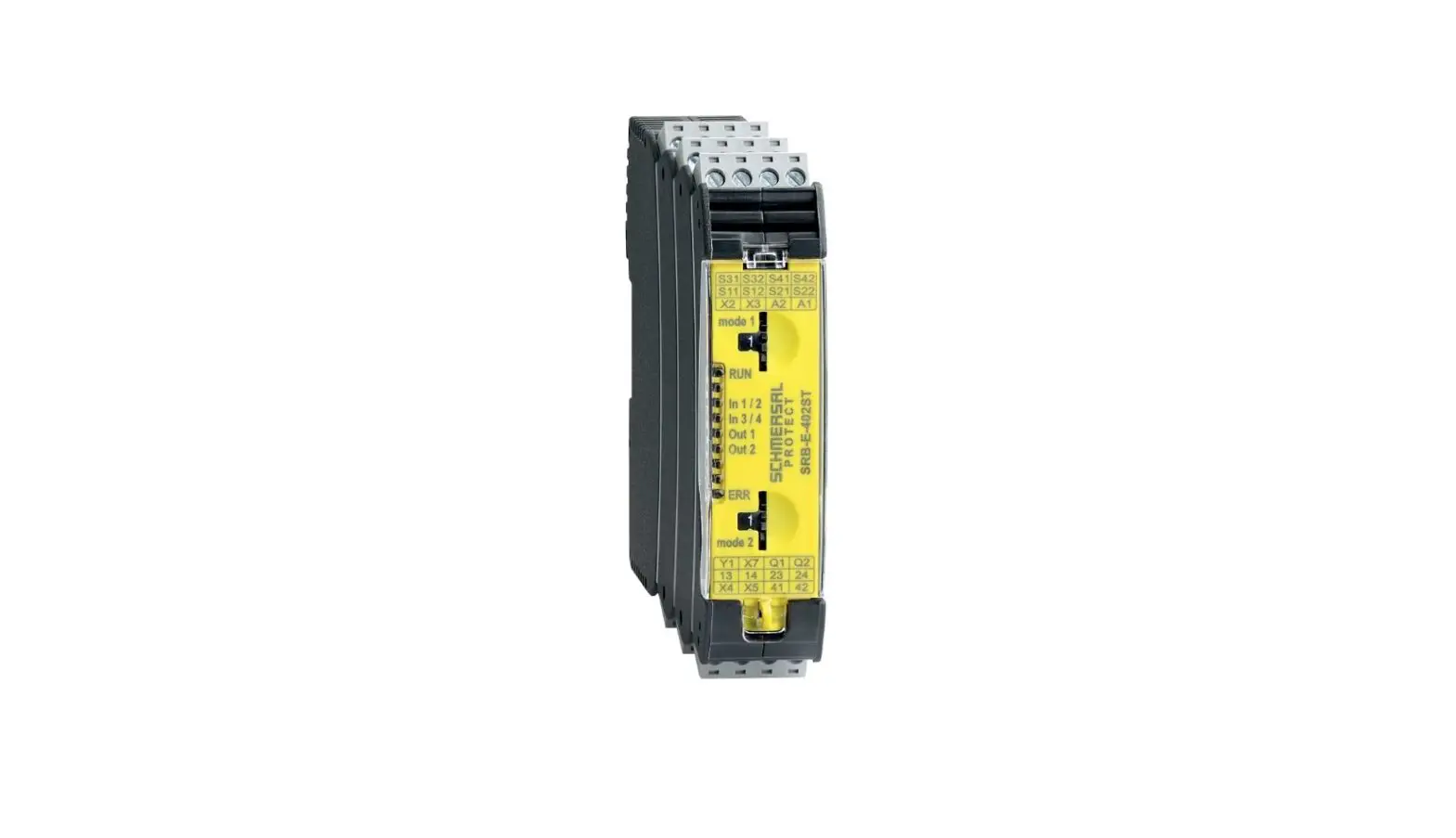
SCHMERSAL SRB-E-402ST Safety Monitoring Module Instruction Manual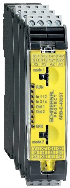
About this document
Function
This operating instructions manual provides all the information you need for the mounting, set-up and commissioning to ensure the safe operation and disassembly of the safety-monitoring module. The operating instructions must be available in a legible condition and a complete version in the vicinity of the device.
Target group: authorised qualified personnel
All operations described in this operating instructions manual must be carried out by trained specialist personnel, authorised by the plant operator only.
Please make sure that you have read and understood these operating instructions and that you know all applicable legislations regarding occupational safety and accident prevention prior to installation and putting the component into operation.
The machine builder must carefully select the harmonised standards to be complied with as well as other technical specifications for the selection, mounting and integration of the components
Explanation of the symbols used
 Information, hint, note:
This symbol is used for identifying useful additional information.
![]() Caution: Failure to comply with this warning notice could lead to failures or malfunctions.
Caution: Failure to comply with this warning notice could lead to failures or malfunctions.
Warning: Failure to comply with this warning notice could lead to physical injury and/or damage to the machine.
Appropriate use
Products in Schmersal’s range are not intended to be used by private end consumers.
The products described in these operating instructions are developed to execute safety-related functions as part of an entire plant or machine. It is the responsibility of the manufacturer of a machine or plant to ensure the correct functionality of the entire machine or plant.
The safety-monitoring module must be exclusively used in accordance with the versions listed below or for the applications authorised by the manufacturer. Detailed information regarding the range of applications can be found in the chapter “Product description”.
General safety instructions
The user must observe the safety instructions in this operating instructions manual, the country-specific installation standards as well as all prevailing safety regulations and accident prevention rules.
Further technical information can be found in the Schmersal catalogues or in the online catalogue on the Internet: products.schmersal.com.
The information contained in this operating instructions manual is provided without liability and is subject to technical modifications. There are no residual risks, provided that the safety instructions as well as the instructions regarding mounting, commissioning, operation and maintenance are observed.
![]() Warning about misuse
Warning about misuse
In case of inadequate or improper use or manipulations of the safety-monitoring module, personal hazards or damage to machinery or plant components cannot be excluded.
Exclusion of liability
We shall accept no liability for damages and malfunctions resulting from defective mounting or failure to comply with this operating instructions manual. The manufacturer shall accept no liability for damages resulting from the use of unauthorised spare parts or accessories.
For safety reasons, invasive work on the device as well as arbitrary repairs, conversions and modifications to the device are strictly forbidden; the manufacturer shall accept no liability for damages resulting from such invasive work, arbitrary repairs, conversions and/or modifications to the device.
The safety relay module is to be operated in an area in which access by personnel is restricted.
Product description
Ordering code
This operating instructions manual applies to the following types:
| SRB-E-402ST-① | ||
| No. | Option | Description |
| ① | Plug-in screw clamps: single wire (rigid) or fine wire (flexible): 0.2 … 2.5 mm²; fine wire with ferrule: 0.25 … 2.5 mm² | |
| CC | Plug-in cage clamps: single wire (rigid) or fine wire (flexible): 0.2 … 1.5 mm²;fine wire with ferrule: 0.25 … 1.5 mm² | |
![]() Only if the action described in these operating instructions is carried out correctly will the safety function be safeguarded, including compliance with the Machinery Directive.
Only if the action described in these operating instructions is carried out correctly will the safety function be safeguarded, including compliance with the Machinery Directive.
Special versions
For special versions, which are not listed in the order code below 2.1, these specifications apply accordingly, provided that they correspond to the standard version.
Destination and use
The safety-monitoring modules for integration in safety circuits are designed for fitting in control cabinets. They are used for the safe evaluation of the signals of positive break position switches or safety sensors for safety functions on sliding, hinged and removable safety guards as well as emergency stop control devices, safety solenoid switches and AOPD’s.
The safety function is defined as deactivating outputs Q1, Q2 and 13/14, 23/24 when inputs S12, S32 and/or S22, S42 are opened. Taking account of a PFH value assessment, the safety-relevant current paths meet the following requirements (see also chapter 2.6 “Safety classification”):
- Category 4 – PL e to EN ISO 13849-1
- SIL 3 to IEC 61508 and EN 62061
To determine the Performance Level (PL) to EN ISO 13849-1 of the entire safety function (e.g. sensor, logic, actuator), an assessment of all relevant components is required.
![]() The entire concept of the control system, in which the safety component is integrated, must be validated to the relevant standards.
The entire concept of the control system, in which the safety component is integrated, must be validated to the relevant standards.
Technical data
- Standards: EN 60204-1, EN 60947-5-1, EN ISO 13849-1,
- IEC 61508, EN 62061
- EMC rating: to EMC Directive
Air clearances and creepage distances: to EN 60664-1 - Mounting: standard rail to EN 60715
- Terminal designations: EN 60947-1
lectrical characteristics:
Rated operating voltage Ue: 24 VDC –20%/+20%, residual ripple max. 10%
Mains unit/mains power supply: An ES1 or PELV/SELV mains adapter must be used as a voltage source or be ensured by means of additional measures so that the output voltage of the power adapter in the event of an error does not exceed 60 V. Mains power supply must harmonise with device safety (characteristic/melting property) so that triggering is ensured.
Power consumption: 3.6 W (+ load of the safety outputs)
Fuse rating for the operating voltage: We recommend a circuit breaker type Z (max. 16 A) or a fine fuse (max. 15 A, delayed action).
UL Rating of external fuse: max. 16 A, only use fuses in accordance with UL 248 series
- Insulation values to EN 60664-1:
- Rated insulation voltageUi
- – safety contacts: 250 V
- – safety outputs: 50V
- Rated impulse withstand voltageUimp:
- – safety contacts: 6 kV
- – safety outputs: 0.8 kV
- Overvoltage category: III
- Degree of pollution: 2
- Pull-in delay: < 150 ms
- Drop-out delay in case of “emergency stop”: < 10 ms
- Drop-out delay on “supply failure”: < 10 ms
- Bridging in case of voltage drops: typ. 5 ms
- Readiness after switching on voltage: < 1.5 s
Control current circuits/inputs:
- Inputs S12, S22, S32, S42: 24 VDC / 8 mA
- Inputs X2, X3, X4, X5, X7: 24 VDC / 8 mA
- Clock outputs S11, S21, S31, S41: > 20 VDC, 10 mA per output
- Cable length: 1,500 m with 1.5 mm²; 2,500 m with 2.5 mm²
- Conduction resistance: max. 40 Ω
Relay outputs
| Switching capacity of the safety contacts: | 3-14, 23-24: max. 250 V, 6 A ohmic, min. 10 VDC / 10 mA (Derating see 2.5 |
| Fuse rating of the safety contacts: | ternal (Ik = 1000 A) to EN 60947-5-1 Safety fuse 10 A quick blow, 6 A slow blow |
| Utilisation category to EN 60947-5-1 | AC-15: 230 V / 4 A DC-13: 24 V / 4 A |
| Switching capacity of the auxiliary contacts: | 41-42: 24 VDC / 1 A |
| Fuse rating for the auxiliary contact: | safety fuse 2.5 A quick blow, 2 A slow blow |
| Safety contact values | resistance max. 100 mΩ, AgNi, self-cleaning, positive action |
| Electrical life: | refer to 2.5 |
| Mechanical life: | 10 million operations |
Semi-conductor outputs:
- Switching capacity of the safety outputs Q: max. 2 A
- Voltage drop: < 0.5 V
- Leakage current: < 1 mA
- Max. fuse rating of the safety outputs: refer to “Operating voltage”
- Test impulse to Q1, Q2: < 1 ms (negative) < 100 µs (positive)
- Utilisation category to EN 60947-5-1: DC-13: 24 V / 2 A
- Switching capacity of signaling outputs: semi-conductor output Y1: 24 VDC/100 mA
- Fuse rating of the signalling outputs: internal electronic trip, tripping current > 100 mA
- Max. switching cycles / minute: 20
- Inductive consumers: Provision is to be made for suitable protective wiring for suppression.
Mechanical data:
- Connection type: refer to 2.1
- Cable section: refer to 2.1
- Connecting cable: rigid or flexible
- Tightening torque for the terminals: 0.5 Nm
- Material of enclosure: glass-fibre reinforced thermoplastic, ventilated
- Weight: 190 g
Ambient conditions:
Ambient temperature: –25°C … +60°C (non condensing)
Storage and transport temperature: –40°C … +85°C (non condensing)
Degree of protection: Enclosure: IP40
Terminals: IP20
Clearance: IP54 Resistance to shock: 30 g / 11 ms Resistance to vibrations
to EN 60068-2-6: 10 … 55 Hz, amplitude 0.35 mm
Altitude: max. 2,000 m
Derating / electrical lifespan of safety contacts
No derating with individual installation of modules.
Derating on request if several modules are installed one after the other without spacing and with maximum output load and ambient temperatures.
Electrical life of the safety contacts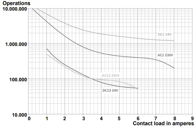
Safety classification
Safety classification of semi-conductor output
- PL: e
- Category: 4
- PFHD: ≤ 2.66 x 10⁻⁹ / h
- PFDavg: ≤ 2.42 x 10⁻⁵
- SIL: suitable for SIL 3 applications
- Mission time: 20 years
Classification of relay output
- Standards: EN ISO 13849-1, IEC 61508, EN 62061
- PL: e
- Category: 4
- DC: high
- CCF: > 65 points
- PFHD: ≤ 1.25 x 10⁻⁸ / h
- PFDavg: ≤ 5.3 x 10⁻⁵
- SIL: suitable for SIL 3 applications
- Mission time: 20 years
The PFH value of 1.25 × 10⁻⁸/h applies to the combinations of contact load (current through enabling contacts) and number of switching cycles (nop/y) mentioned in the table below. At 365 operating days per year and a 24-hours operation, this results in the below-mentioned switching cycle times (tcycle) for the relay contacts. Diverging applications upon request
Contact load
20 %
40 %
60 %
80 %
100 %
Mounting
General mounting instructions
Mounting: snaps onto standard rails to EN 60715.
Hook bottom of enclosure in rail and push down until it engages in position.
Dimensions
Device dimensions (H/W/D): 98 x 22.5 x 115 mm
Electrical connection
General information for electrical connection
![]() The electrical connection may only be carried out by authorised personnel in a de-energised condition.
The electrical connection may only be carried out by authorised personnel in a de-energised condition.
![]() If mains unit is a new installation or a replacement, the connector of the output level must be removed and correct connection of the power supply (A1) must be checked.
If mains unit is a new installation or a replacement, the connector of the output level must be removed and correct connection of the power supply (A1) must be checked.
To avoid EMC disturbances, the physical ambient and operational conditions at the place where the product is installed, must meet the provisions laid down in the paragraph “Electromagnetic Compatibility (EMC)” of EN 60204-1.
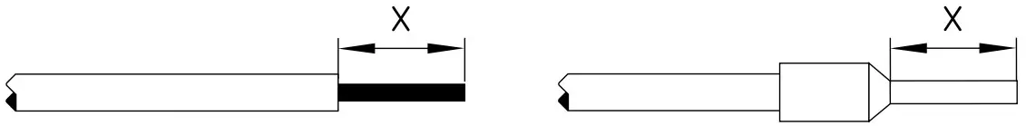
Settle length x of the conductor:
- on screw terminals: 7 mm
- on cage clamps of type s or f: 10 mm

Coding of connecting terminals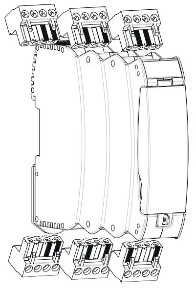
Operating principle and settings
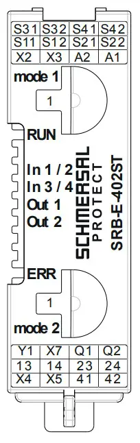
Description of the terminals and LED indications
| Pin | Function | LED | Function |
| A1 | Operating voltage+ 24 VDC | RUN | Operating voltage OK RUN modeFor flash code,see section 6.1 |
| A2 | Operating voltage0 V | ||
| ERR | Error coderefer to part 6.2 | ||
| X2/X4 | Inputsstart circuit | ||
| X3/X5 | Inputsfeedback circuit | ||
| X7 | InputRelease signal | ||
| S11/S21S31/S41 | Test pulse outputs | ||
| S12 S22 | Input channel 1Input channel 2 | In1/2 | High level at S12/S22 For flash code,see section 6.1 |
| S32 S42 | Input channel 1Input channel 2 | In3/4 | High level at S32/S42 For flash code,see section 6.1 |
| Y1 | Signalling output (NC) | ||
| 41/42 | Signalling contact (NC) | ||
| 13/14,23/24, | Safety outputs (safety function 1) | Out 1 | Outputs activated For flash code,see section 6.1 |
| Q1/Q2 | Safety outputs (safety function 2) | Out 2 | Outputs activated For flash code,see section 6.1 |
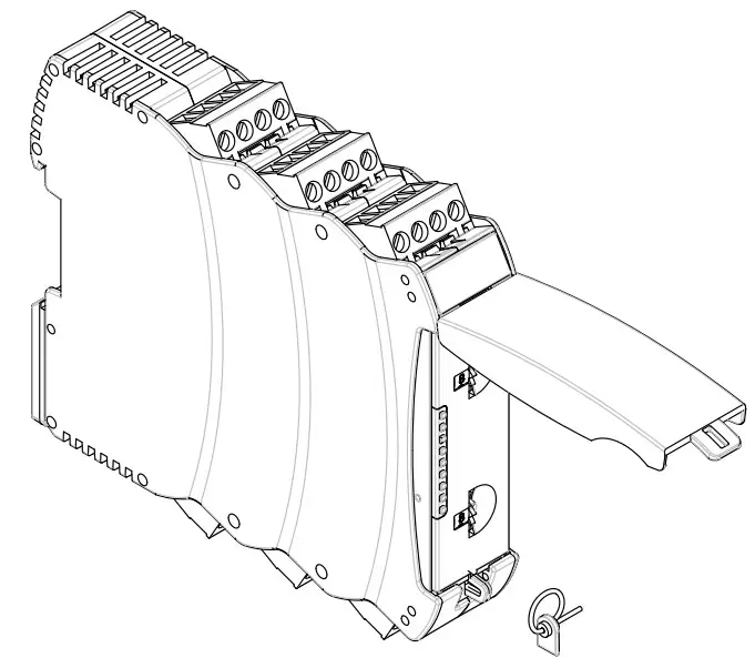
Adjustment of application using rotary “mode” switch
- Open front transparent cover (see fig.).
- Opening is carried out by lifting side with lock.
- Select desired application for safety function 2 using rotary mode switch 2 (1 … 11) by turning up or down (see 5.3).
- Select desired application for safety function 1 using rotary mode switch 1 (1 … 10) by turning up or down (see 5.3).
- After performing setting, close front cover again.
- Front cover can be secured with a lead seal to protect it from being opened unintentionally
![]() Only touch the components after electrical discharge!
Only touch the components after electrical discharge!
Applications for two safety functions can be set separately using rotary mode switch 1 and 2
| Rotary knob position | Reset button (detection of the trailing edge) | Cross-wire monitoring active | Input / Sensor configuration | Monitoring of sensor channels for synchronisation (< 5 s) |
| 1 | Yes | Yes | NC / NC | Yes |
| 2 | Yes | Yes | NC / NC | No |
| 3 | Yes | No | NC / NC | Yes |
| 4 | Yes | No | NC / NC | No |
| 5 | Yes | Yes | NC / NO | Yes |
| 6 | Autostart | Yes | NC / NO | No |
| 7 | Autostart | Yes | NC / NC | Yes |
| 8 | Autostart | Yes | NC / NC | No |
| 9 | Autostart | No | NC / NC | Yes |
| 10 | Autostart | No | NC / NC | No |
| 11 | Two-hand function type IIICOnly rotary mode switch 2 | NC, NO / NC, NO | < 0.5 s(upon actuation of setting elements) | |
| 12 | Two-hand function type IIIAOnly rotary mode switch 2 | NO / NO | < 0.5 s(upon actuation of setting elements) | |
| C | Configuration mode | |||
Changing setting or application
| Description / procedure | Rotary (mode) switch | System response | LED indications | ||||
| RUN | In 1/2 | In 3/4 | Out 1 | Out 2 | |||
| Factory setting | mode 1 and mode 2 in position 1 | Ready for application 1 | – | – | – | – | – |
| Switch operating voltage on | Position 1 | Without connected sensors! | Lights up | – | – | – | – |
| Turn rotary mode switch 1to position C | Application 1 is deleted | Lights up | Flashes | Flashes | Flashes | Flashes | |
| Setting cycle active | Application 1 is deleted | – | – | – | – | – | |
| No valid application stored | Flashes | – | – | – | – | ||
| SRB-E ready for new applications | |||||||
| Select mode 2, application 2 | Select desired application (1-11) | Flashes | – | – | – | – | |
| Select mode 1, application 1 | Set desired application (1-10)(time window for setting procedure approx. 3 sec.) | New applications will be loaded | Lights up | – | – | – | – |
| Setting cycle active | Lights up | Lights up | – | – | – | ||
| Lights up | Lights up | Lights up | – | – | |||
| Lights up | Lights up | Lights up | Lights up | – | |||
| Lights up | Lights up | Lights up | Lights up | Lights up | |||
| Ready for operation | The desired applications areconfigured | Adopt new application | Lights up | – | – | – | – |
| Switch off operating voltage and connect wires according to selected application -> SRB-E… ready for operation | |||||||
Diagnostic
LED indications
| LED | Function | Display type |
| RUN | Ready for operation | Continuously lit |
| Not a valid application | Flashes | |
| In 1/2 | Input S12 and S22 closed | Continuously lit |
| Time window for synchronicity exceeded | Flashes quickly | |
| 1-channel opening | Flashes slowly | |
| In 3/4 | Input S32 and S42 closed | Continuously lit |
| Time window for synchronicity exceeded | Flashes quickly | |
| 1-channel opening | Flashes slowly | |
| Out 1 | Safety output application 1 ON | Continuously lit |
| Safety outputs waiting for start (input X2) | Flashes slowly | |
| Feedback circuit not closed (input X3) | Flashes slowly | |
| Out 2 | Safety outputs application 2 ON | Continuously lit |
| No release signal on input X7 | Flashes quickly | |
| Safety outputs waiting for start (input X4) | Flashes slowly | |
| Feedback circuit not closed (input X5) | Flashes slowly |
Malfunctions
Malfunctions and fault causes are displayed with the ERR-LEDs via short and long flashing signals
| LED | Error cause | Long flash | Short flash |
| Operating voltage too low | 1 | 1 | |
| Operating voltage too high | 1 | 2 | |
| Invalid rotary switch setting | 1 | 3 | |
| External voltage on output Q1 | 1 | 5, 7, 9 | |
| External voltage on output Q2 | 1 | 6, 8 | |
| 2 | 1 | ||
| Termination to GND on output Q1 | 2 | 2 | |
| Termination to GND on output Q2 | 2 | 3 | |
| Cross-wire between inputs | 2 | 4 | |
| S12 and S22 | |||
| Cross-wire between inputs | 2 | 5 | |
| S32 and S42 | |||
| Undefined level on outputs: | |||
| X2 | 3 | 4 | |
| X3 | 3 | 5 | |
| ERR | X4 | 3 | 6 |
| X5 | 3 | 7 | |
| X7 | 3 | 9 | |
| S12 | 2 | 9 | |
| S22 | 3 | 1 | |
| S32 | 3 | 2 | |
| S42 | 3 | 3 | |
| Rotary switch > 30 sec. to position C | 6 | 8 | |
| Application changed | LEDs flash quickly: | ||
| and activation of | RUN, In 1/2, In 3/4, | ||
| operating voltage | Out 1, Out 2 | ||
| Application was | LEDs flash quickly: | ||
| changed during | In 1/2, In 3/4, | ||
| active operation | Out 1, Out 2 | ||
| Other fault codes: | |||
| Consult technical sales dept. at Schmersal | |||
Wiring examples
Possible application
All applications for 1 or 2-channel safe evaluation for protective equipment as follows:
- Safety door monitoring to EN ISO 14119
- Position switches with positive break to EN 60947-5-1
- Safety sensors to EN 60947-5-3
- Emergency stop command devices to EN ISO 13850 and EN 60947-5-5
- Magnetic safety sensors to EN 60947-5-3
- Safety light curtain and photoelectric barriers according to EN 61496
- Two-hand control panels to EN ISO 13851 type IIIA and IIIC
The connection of magnetic safety switches to the SRB-E-… safety-monitoring module is only admitted when the requirements of the standard EN 60947-5-3 are observed.
![]() As the technical data are regarded, the following minimum requirements must be met:
As the technical data are regarded, the following minimum requirements must be met:
- Switching capacity: min. 240 mW
- Switching voltage: min. 24 VDC
- Switching current: min. 10 mA
![]() For example, the following safety sensors meet the requirements:
For example, the following safety sensors meet the requirements:
- BNS 36-02Z(G), BNS 36-02/01Z(G)
- BNS 260-02Z(G), BNS 260-02/01Z(G)
![]() When sensors with LED are wired in the control circuit (protective circuit), the following rated operating voltage must be observed and respected:
When sensors with LED are wired in the control circuit (protective circuit), the following rated operating voltage must be observed and respected:
- 24 VDC with a max. tolerance of –5%/+20%
Otherwise availability problems could occur, especially in series-wired sensors, where a voltage drop in the control circuit is triggered by LED’s for instance.
![]() The two hand control only offers protection for the person using it.
The two hand control only offers protection for the person using it.
Application example
Dual-channel control, shown for guard door monitoring with two position switches where one has a positive break contact; with external reset button j
- Relay outputs: Suitable for 2-channel control, for increase in capacity or number of contacts by means of contactors or relays with positiveguided contacts
- s = Feedback circuit
![]() Signalling outputs must not be used in safety circuits.
Signalling outputs must not be used in safety circuits.
Wiring example SRB-E-402ST
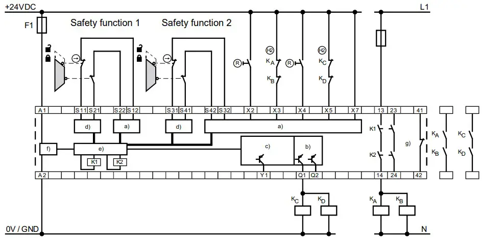
Key
a) Safety inputs
b) Safety outputs Safety function 2
c) Signalling outputs
d) Clock outputs
e) Processing
f) Power
g) Safety function 1
Start configuration
External reset button
- Manual start or activation of the module occurs when the button is released.
Monitoring of max. actuation time 0.03 s … 3 s. If the time is exceeded, the module cannot be started!
Reset without monitoring / autostart
- The manual start or the activation of the module occurs when the button is pressed (not when it is released!).
- With autostart, X2 / X4 must be bridged to S11, S21, S31, S41 or +24 VDC
![]() Not admitted without additional measure due to the risk of gaining access by stepping behind!
Not admitted without additional measure due to the risk of gaining access by stepping behind!
![]() Within the meaning of EN 60204-1 paragraph 9.2.3.4.2 the operating mode “automatic start” is only restrictedly admissible. In particular, any inadvertent restart of the machine must be prevented by other suitable measures.
Within the meaning of EN 60204-1 paragraph 9.2.3.4.2 the operating mode “automatic start” is only restrictedly admissible. In particular, any inadvertent restart of the machine must be prevented by other suitable measures.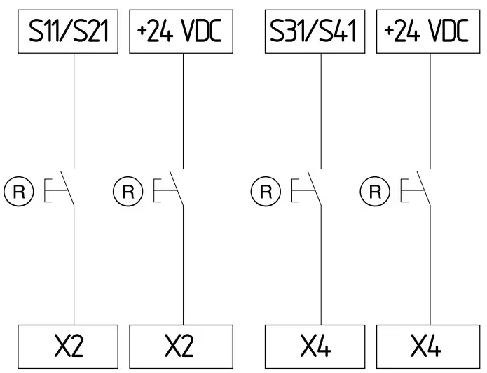
| Reset button (detection of the trailing edge) | Reset without monitoring / autostart |
| Rotary knob position 1 | Rotary knob position 6 |
| Rotary knob position 2 | Rotary knob position 7 |
| Rotary knob position 3 | Rotary knob position 8 |
| Rotary knob position 4 | Rotary knob position 9 |
| Rotary knob position 5 | Rotary knob position 10 |
Feedback circuit / Release signal
- Suitable for increase in capacity or number of contacts by means of contactors or relays with positive-guided contacts. If the feedback circuit is not required, establish a bridge.

- The safety outputs Q1 and Q2 can be switched during operation via the safety input X7 with the guard system closed.
- For safety-orientated use, a fault in the wiring (short circuit to 24 V potential) must be able to be excluded!
- If no deactivation during operation is required, this input must be switched to + 24 VDC.

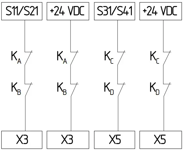
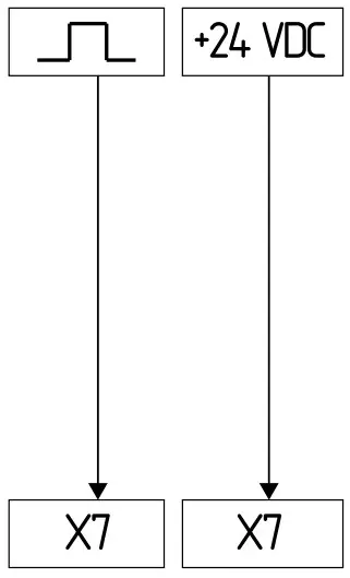
![]() = control signal
= control signal
Sensor configuration
Single channel signal processing
Safety function 1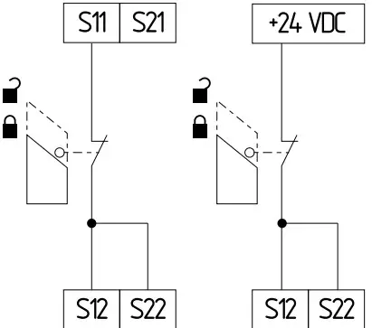
Safety function 1 Safety function 2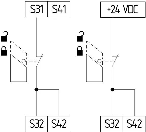
| Rotary knob position | Function |
| 4 | Reset button (detection of the trailing edge) |
| 10 | Reset without monitoring / autostart |
Dual channel signal processing NC / NC
With cross-wire monitoring
(Cat. 4 – PL e to EN ISO 13849-1 possible)
Safety function 1
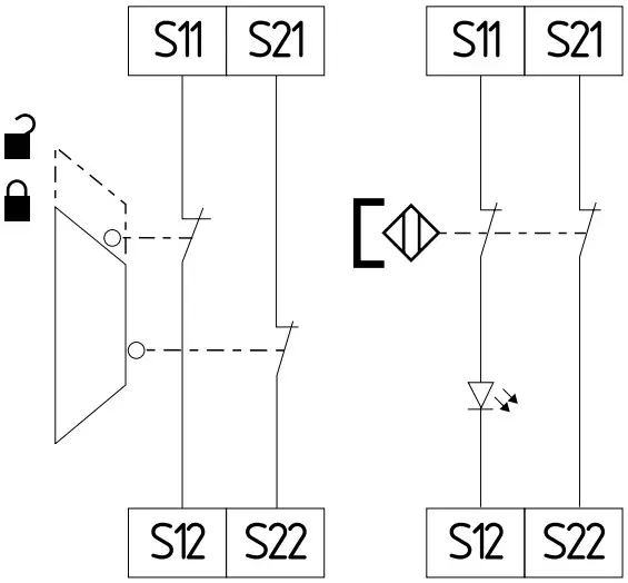
Safety function 2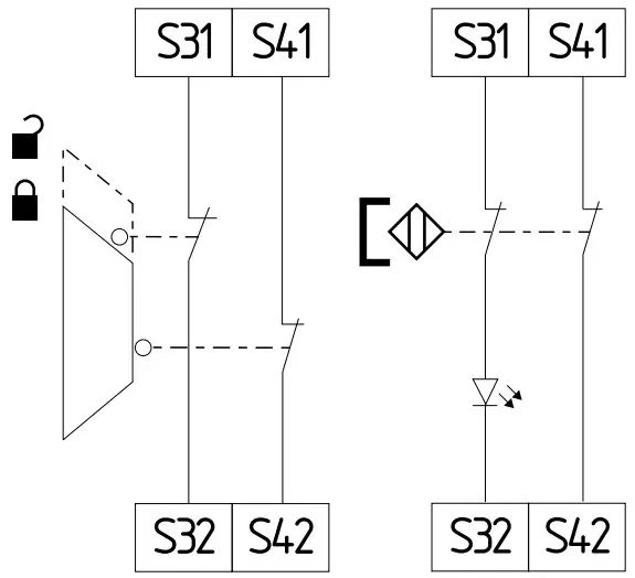
| Rotary knob position | Cross-wire monitoring | Synchronisation |
| 1 | Yes | Yes |
| 2 | Yes | No |
| 7 | Yes | Yes |
| 8 | Yes | No |
Without cross-wire monitoring
(Cat. 4 – PL e to EN ISO 13849-1 only possible with protective wiring)
Safety function 1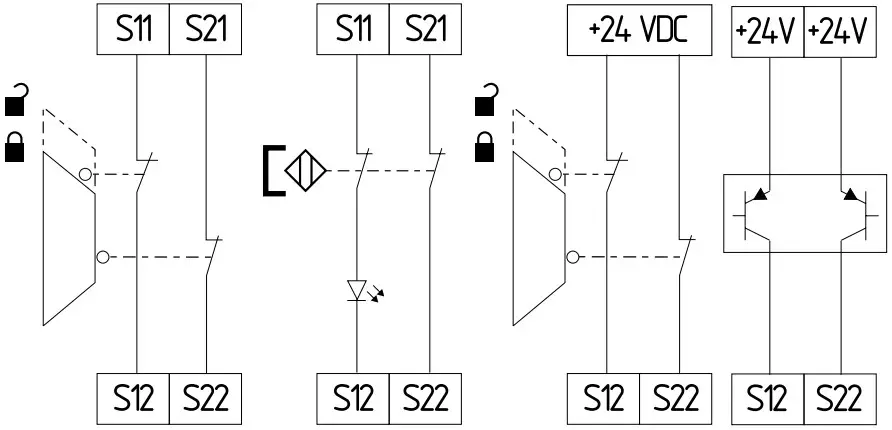
Safety function 2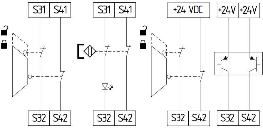
| Rotary knob position | Cross-wire monitoring | Synchronization |
| 3 | No | Yes |
| 4 | No | No |
| 9 | No | Yes |
| 10 | No | No |
Dual channel signal processing NC / NO
(Cat. 4 – PL e to EN ISO 13849-1 possible)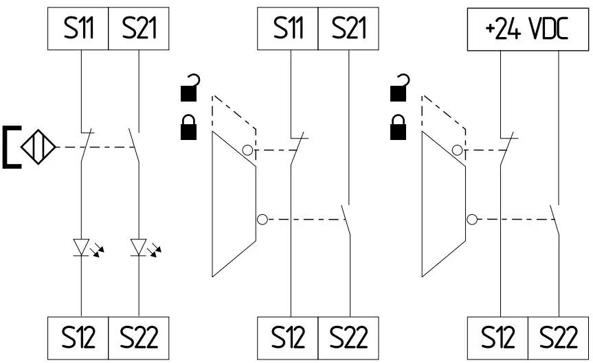
Safety function 2
| Rotary knob position | Function |
| 5 | Reset button (detection of the trailing edge) |
| 6 | Reset without monitoring / autostart |
Two-hand control type IIIC safety function 2 (Only rotary mode switch 2)
- Malfunctions of every contact as well as earth leakages and crosswire shorts are detected.
- The feedback circuit s is integrated as shown. The safety-technical function of external positive-guided contactors is monitored by a series-wiring of the NC contacts with the input X7. In idle state, this circuit must be closed.
- If the feedback circuit is not required, establish a bridge.

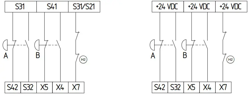
| Rotary knob position | Function |
| 11 | Function two-hand control type |
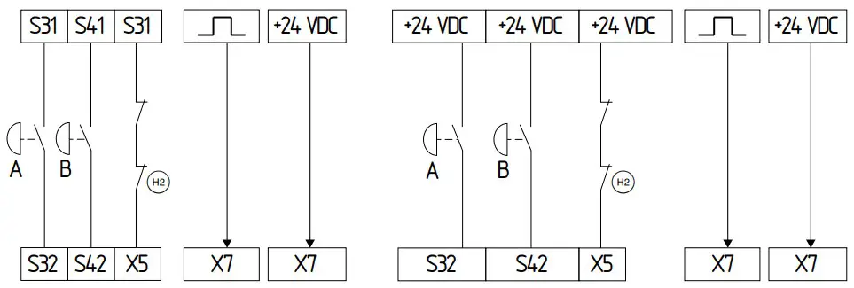
Two-hand control type IIIA safety function 2 (Only rotary mode switch 2)
- Malfunctions in the button contact as well as short circuit to earth are detected.
- The feedback circuit s is integrated as shown. The safety-technical function of external positive-guided contactors is monitored by a series-wiring of the NC contacts with the input X5. In idle state, this circuit must be closed.
- If the feedback circuit is not required, establish a bridge.
- Safety outputs Q1 / Q2 can be switched off during normal operation via safety input X7. If this function is not required, input X7 must be connected to + 24 VDC

Set-up and maintenance
Commissioning
The safety relay module features protection class IP54 for installation in a switch cabinet.
The safety relay module is delivered ready for operation.
Application 1 has already been preset in the factory for both safety functions.
Functional testing
The safety function of the safety-monitoring module must be tested. The following conditions must be previously checked and met:
- Correct fixing
- Check the integrity of the cable entry and connections
- Check the safety-monitoring module’s enclosure for damage
- Check the electrical function of the connected sensor technology and their influence on the safety-monitoring module and the downstream actuators
The safety relay module features self-test functions. If a fault is detected, the system adopts a safe mode and leads, if necessary, to undelayed deactivation of all safety outputs.
Behaviour in the case of faults
In the event of a fault the following procedure is recommended:
- Identify faults according to flash codes from chapter 6.2.
- Rectify the fault if it is described in the table.
- Switch operating voltage off and on and erase fault mode. If fault could not be rectified, please contact the manufacturer
Setting report
This report regarding the setting of the device must be completed accordingly by the customer and enclosed in the technical documentation of the machine.
The setting report must be available whenever a safety check is performed.
Company:
The safety-monitoring module is used in the following machine:
Machine n° Machine type Module n°
Configured application (mode 1):
Configured application (mode 2):
Set on (date) Signature of the responsible person
Maintenance
A regular visual inspection and functional test, including the following steps, is recommended:
- Check the correct fixing of the safety-monitoring module
- Check the cable for damages
- Check electrical function
![]() Remark only relevant for relay outputs:
Remark only relevant for relay outputs:
If a manual functional check is necessary to detect a possible accumulation of faults, then this must take place during the intervals noted as follows:
- at least every month for PL e with category 3 or category 4 (according to EN ISO 13849-1) or SIL 3 with HFT (hardware fault tolerance) = 1 (according to EN 62061);
- at least every 12 months for PL d with category 3 (according to EN ISO 13849-1) or SIL 2 with HFT (hardware fault tolerance) = 1 (according to EN 62061)
Damaged or defective components must be replaced.
Disassembly and disposal
Disassembly
The safety-monitoring module must be disassembled in a de-energised condition only.
Disposal
The safety-monitoring module must be disposed of in an appropriate manner in accordance with the national prescriptions and legislations.
Appendix
Wiring/circuit information
Use of safety outputs
Safety contacts 13/14, 23/24 (safety contact 1) and safety outputs Q1, Q2 (safety function 2) work independently of each other. Depending on the application, various hierarchies can be realised through external wiring of the safety contacts and safety outputs.
Air clearances and creepage distances of the safety contacts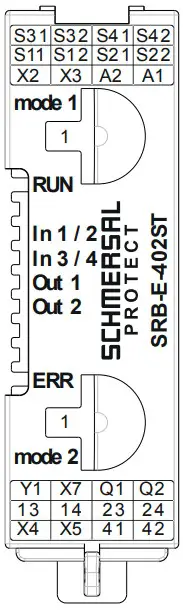
Against all other connection terminals, the safety contacts 13-14 and 23-24 comply without additional measures with the requirements for double insulation in accordance with EN 60664-1 and are to be used with switch voltages > 50 V.
EU Declaration of conformity
Original K.A. Schmersal GmbH & Co. KG
Möddinghofe 30
42279 Wuppertal
Germany
Internet: www.schmersal.com
We hereby certify that the hereafter described components both in their basic design and construction conform to the applicable European Directives.
Name of the component: SRB-E-402ST
Type: See ordering code
Description of the component: Safety-monitoring module for emergency stop circuits,
guard door monitoring, magnetic safety switches, two-hand control panels and AOPD’s
Relevant Directives: Machinery Directive EMC-Directive RoHS-Directive
2006/42/EC
2014/30/EU
2011/65/EU
Applied standards:
EN ISO 13851:2019
EN ISO 13849-1:2015
EN ISO 13849-2:2012
IEC 61508 parts 1-7:2010
EN 62061:2005 + Cor.:2010 + A1:2013 + A2:2015\
Notified body, which approved the full quality assurance system, referred to in Appendix X, 2006/42/EC:
TÜV Rheinland Industrie Service GmbH Am Grauen Stein, 51105 Köln ID n°: 0035
Person authorised for the compilation of the technical documentation:
Oliver Wacker
Möddinghofe 30
42279 Wuppertal
Place and date of issue: Wuppertal, March 14, 2023

Authorised signature
Philip Schmersal
Managing Director
The currently valid declaration of conformity can be downloaded from the internet at products.schmersal.com
K.A. Schmersal GmbH & Co. KG
Möddinghofe 30, 42279 Wuppertal
Germany
Phone: +49 202 6474-0
Telefax: +49 202 6474-100
E-Mail: [email protected]
Internet: www.schmersal.com