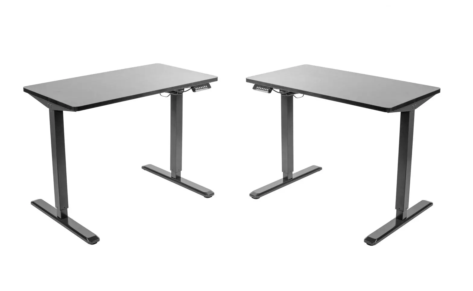
VIVO Black 43″ x 24″ Electric Desk Instruction Manual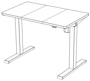
SKU: DESK-EP43TB
Scan the QR code with your mobile device or follow the link for helpful videos and specifications related to this product. https://vivo-us.com/products/desk-ep43tb
GET IN TOUCH | Monday-Friday from 7:00am-7:00pm CST![]() [email protected]
[email protected] ![]() www.vivo-us.com Chat live with an agent!
www.vivo-us.com Chat live with an agent! ![]() 309-278-5303
309-278-5303
![]() WARNING!
WARNING!
If you do not understand these directions, or if you have any doubts about the safety of the installation, please call a qualified technician. Check carefully to make sure there are no missing or defective parts. Improper installation may cause damage or serious injury. Do not use this product for any purpose that is not explicitly specified in this manual and do not exceed weight capacity. We cannot be liable for damage or injury caused by improper mounting, incorrect assembly, or inappropriate use.
 ELECTRICAL SAFETY INSTRUCTIONS
THIS PRODUCT IS POWERED BY ELECTRICITY. IN ORDER TO AVOID BURNS, FIRE AND ELECTRIC SHOCK, PLEASE READ THE FOLLOWING INSTRUCTIONS CAREFULLY.
- DO NOT CLEAN PRODUCT WHILE POWER IS CONNECTED.
- DO NOT DISASSEMBLE OR REPLACE COMPONENTS WHILE POWER ICONNECTED.
- NEVER OPERATE THE SYSTEM WITH A DAMAGED CORD OR PLUG. PLEASE CONTACT YOUR SELLER TO REPLACE DAMAGED PARTS.
- NEVER OPERATE SYSTEM IN DAMP ENVIRONMENTS OR IF ANY ELECTRICAL COMPONENTS HAVE MADE CONTACT WITH LIQUIDS.
- ALTERATIONS OF THE GIVEN POWER UNIT ARE NOT ALLOWED.
- OUTDOOR USE IS PROHIBITED.
WARNING: CHOKING HAZARD
SMALL PARTS – NOT FOR CHILDREN UNDER 3 YEARS. ADULT SUPERVISION I REQUIRED
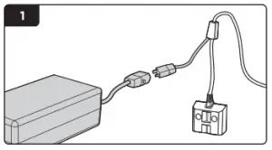
PACKAGE CONTENTS
A (x1)Telescopic Crossbar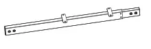
B (x1) Motorized Leg

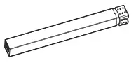
C (x1) Leg
D (x1) Crossbar Spacer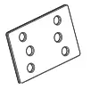
E (x2) Side Bracket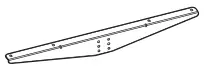
F (x1) Sync Rod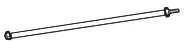
G (x2) Foot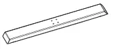
H (x1) Adapter Holder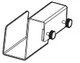
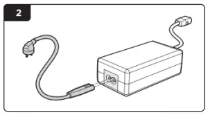
I (x1) AC Adapter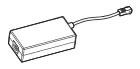
J (x1) Power Cable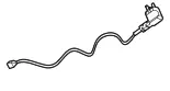
K (x1) Controller

L (x1) Left Desktop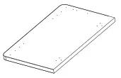
M (x1) Center Desktop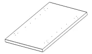
N (x1) Right Desktop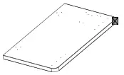
O (x2) Support Pad
P (x24) Flat Head Screw
Q (x4) Desktop Connector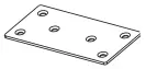
S-A (x16) M6x12
S-B (x12) ST4.2×20 Screw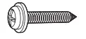
S-C (x2) ST3.5×20 Screw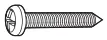
S-D (x3) Cable Clip
S-E (x12) Anti-Vibration Pad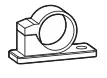
S-F (x1) Allen Wrench
WARNING
PINCH POINT
DO NOT place hands on near support bars. Moving parts can crush and cut. Pinch points are created during lifting and lowering the worksuface.
Failure to follow these instructions may result in serious personal injury
DO NOT EXCEED WEIGHT CAPACITY.
Failure to do so may result in serious injury.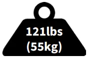
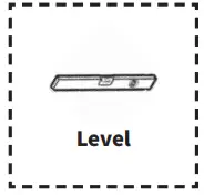
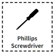
TOOLS NEEDED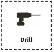
ASSEMBLY STEPS
STEP 1
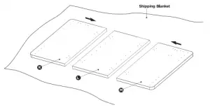
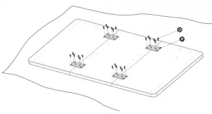
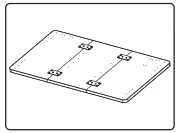
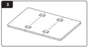
Assemble the desktops (L, M, N) using the desktop connectors (Q) and flat head screws (P). Tighten screws with a Phillips screwdriver.
STEP 2:
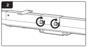
Loosen the two set screws on the telescopic crossbar (A) using the Allen wrench (S-F) and partially extend the crossbar.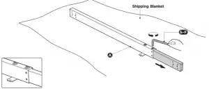
STEP 3:
Place the crossbar spacer (D) on the motorized leg (B) as shown. Attach the telescopic crossbar to the legs (B, C) as shown using M6x12mm bolts (S-A), and tighten with the Allen wrench (S-F). NOTE: Insert all necessary screws into holes before tightening.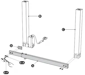
STEP 4:
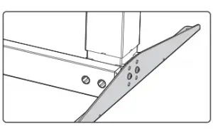
Attach the side brackets (E) to both ends of the frame using four M6x12mm bolts (S-A). Tighten with the Allen wrench (S-F).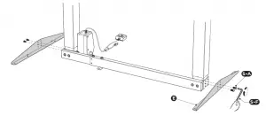
STEP 5
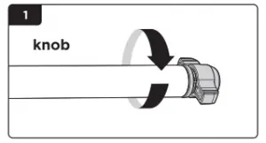
Loosen the knob on the socket end of the sync rod (F) and slide the sync rod onto the shaft of the motorized leg. Tighten the knob.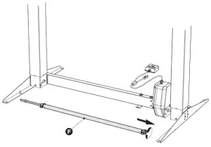

STEP 6
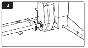
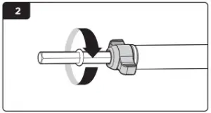
Loosen the knob on the other end of the sync rod and extend the hex shaft into the socket in the leg, making sure the shaft is fully inserted with the red O-ring bumper spaced no more than 0.5” from the leg. Tighten the knob.
STEP 7
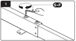
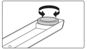
Place the frame upside down on the desktop, extend to match the desktop mounting holes, then tighten the set screws with the Allen wrench (S-F).
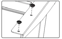
STEP 8
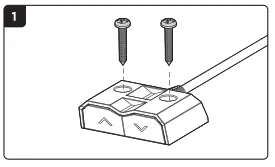
Place the feet (G) on the legs as shown. Insert and tighten bolts (S-A) using the Allen wrench (S-F).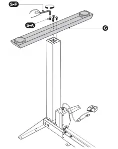
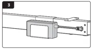
STEP 9
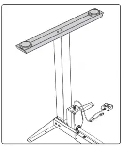
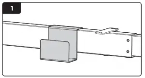
Place the adapter holder (H) over the telescopic crossbar and tighten the two thumbscrews. Place the AC adapter (I) into the adapter holder (H).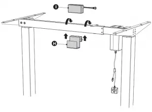
STEP 10
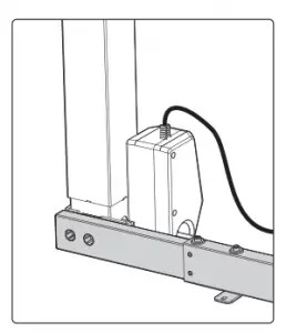
Connect the AC adapter and motorized leg to the controller (K). Connect the power cable (J) to the AC adapter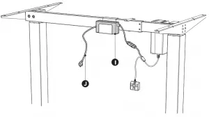
STEP 11
Insert the anti-vibration pads (S-E) into the desktop mounting holes in the crossbar and side brackets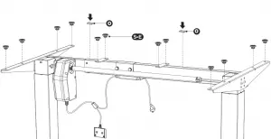
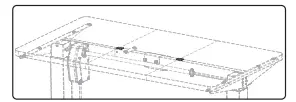
STEP 12
Place the assembled frame on the desktop, making sure the holes are aligned with the desk frame, and secure the frame using ST4.2×20 screws (S-B).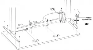
STEP 13
Attach the controller to the underside of the desktop using ST3.5×20 screws (S-C) as shown. Once the controller is installed, cable clips (S-D) can be attached to the desk for cable management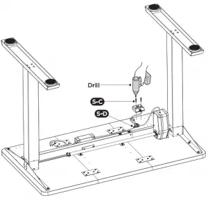
STEP 14
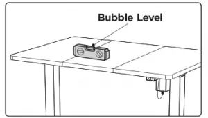
If necessary, adjust foot pads to level the desk. Plug the power cable (J) into an AC wall outlet.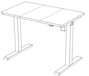
STEP 15
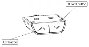
Press and hold the UP or DOWN buttons to operate the desk
DESCRIPTION | RESOLUTION |
No response while pressing button | Check to make sure all cables are fully connected. |
The desktop cannot be lifted | Make sure the desktop and other items do not exceed the weight limit (154lbs). |
Duty cycle exceeded (max. 2min operating) | Allow desk to rest for 30 minutes. |
![]() CAUTION!
CAUTION!
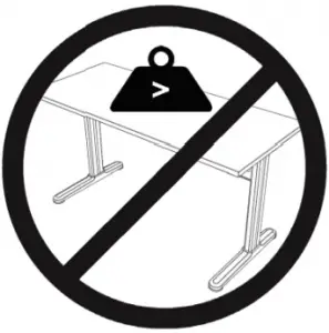
Do not exceed desk weight limit.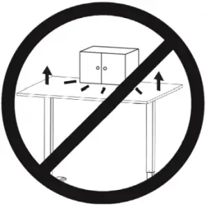
Keep area of vertical motion free of obstacles.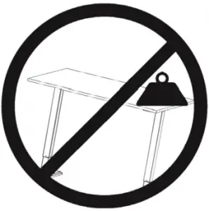
Keep weight on desk balanced for correct
operation and longer life of components.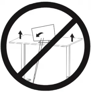
Leave enough slack in cables to allow for
full range of vertical motion.
Failure to follow these instructions may result in property damage and/or personal injury.

Love your new VIVO setup and want to share?
Tag us in your photo! @vivo_us
Open Monday – Friday 7:00am – 7:00pm CST,
our dedicated support team can offer immediate assistance with rapid response times. If any parts are received damaged or defective, please contact us. We are happy to replace parts to ensure you have a fully functioning product.

[email protected]
AVG. RESPONSE TIME (within office hrs): 1HR 8M
– 23% within < 15m
– 38% within < 30m
– 61% within < 1hr
– 83% within < 2hr
– 92% within < 3hr

www.vivo-us.com
Chat live with an agent!
AVG. RESOLUTION TIME (within office hrs): < 15 M

309-278-5303
AVG. RESOLUTION TIME (within office hrs): 5M 4S
FOR MORE VIVO PRODUCTS, CHECK OUT OUR WEBSITE AT: www.vivo-us.com


