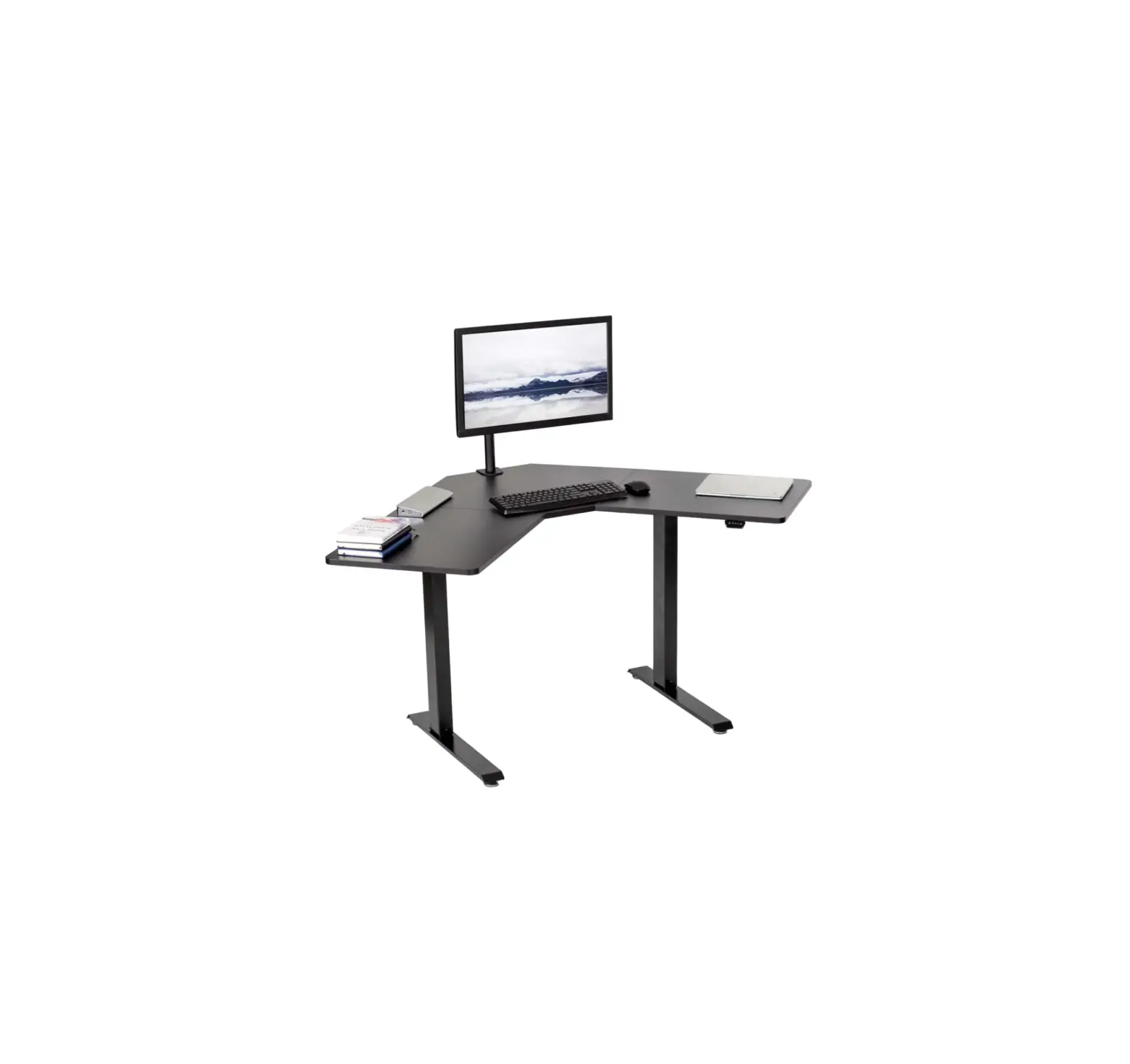
V I V O DESK-E1L94B Black 47 Inch x 47 Inch Corner Electric Desk

![]() WARNING!
WARNING!
If you do not understand these directions, or if you have any doubts about the safety of the installation, please call a qualified technician. Check carefully to make sure there are no missing or defective parts. Improper installation may cause damage or serious injury. Do not use this product for any purpose that is not explicitly specified in this manual and do not exceed weight capacity. We cannot be liable for damage or injury caused by improper mounting, incorrect assembly, or inappropriate use.
 ELECTRICAL SAFETY INSTRUCTIONS
THIS PRODUCT IS POWERED BY ELECTRICITY. IN ORDER TO AVOID BURNS, FIRE AND ELECTRIC SHOCK, PLEASE READ THE FOLLOWING INSTRUCTIONS CAREFULLY.
- DO NOT CLEAN PRODUCT WHILE POWER IS CONNECTED.
- DO NOT DISASSEMBLE OR REPLACE COMPONENTS WHILE POWER IS CONNECTED.
- NEVER OPERATE THE SYSTEM WITH A DAMAGED CORD OR PLUG. PLEASE CONTACT YOUR SELLER TO REPLACE DAMAGED PARTS.
- NEVER OPERATE SYSTEM IN DAMP ENVIRONMENTS OR IF ANY ELECTRICAL COMPONENTS HAVE MADE CONTACT WITH LIQUIDS.
- ALTERATIONS OF THE GIVEN POWER UNIT ARE NOT ALLOWED.
- OUTDOOR USE IS PROHIBITED.
PACKAGE CONTENTS
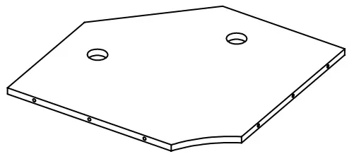
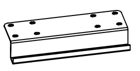
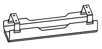
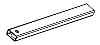
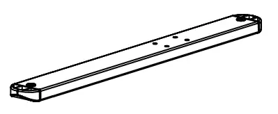
A (x1) Left Panel | B (x1) Middle Panel | C (x1) Right Panel | D (x1) Sync Rod |
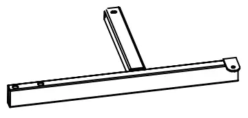
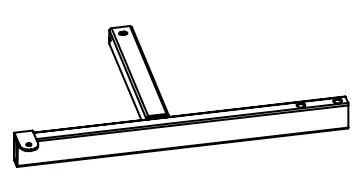
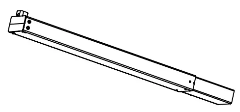
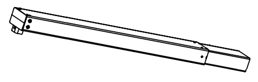
E (x4) Connecting Plate | F (x1) Left Crossbar | G (x1) Right Crossbar | H (x1) Crossbar Connector |
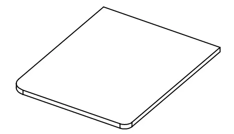
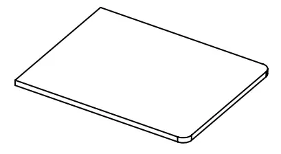
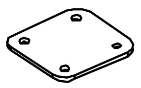
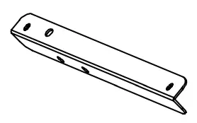
I (x1) Shelf | J (x1) Right Leg | K (x1) Left Leg | L (x1) Left Side Bracket |
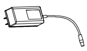
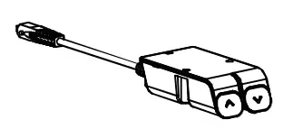
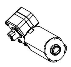
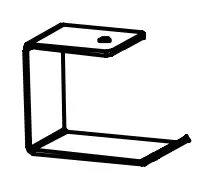
M (x1) Right Side Bracket | N (x1) AC Adapter | O (x1) Control Panel | P (x1) Motor |
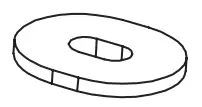
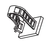
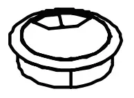
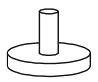
Q (x1) Hook | R (x2) Foot Extension | S (x2) Foot | T (x20) Anti-Vibration Pad |
U (x2) Cable Clip | V (x2) Cable Management Cover | W (x4) Foot Pad | |
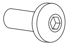
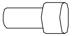
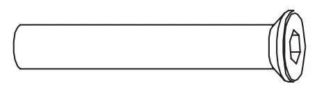
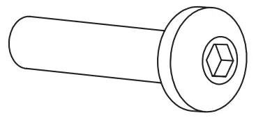
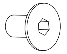
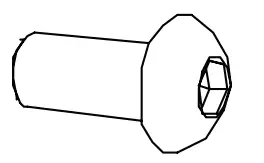
S-A (x43) M5x16mm Screw | S-B (x6) M6x12mm Screw | S-C (x4) M5x12mm Screw | S-D (x4) M8x47mm Screw |
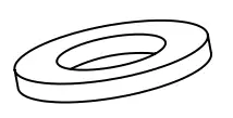
S-E (x8) M6x35mm Screw | S-F (x6) M6x10mm Screw | S-G (x2) M8x12mm Screw | S-H (x2) Washers |
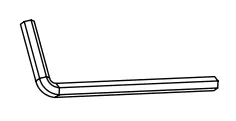
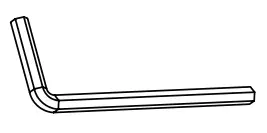
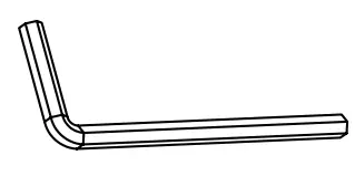
T-A (x1) 2mm Allen Wrench | T-B (x1) 4mm Allen Wrench | T-C (x1) 5mm Allen Wrench |

NOTE: Some hardware may not be used
 WARNING: CHOKING HAZARD
SMALL PARTS – NOT FOR CHILDREN UNDER 3 YEARS. ADULT SUPERVISION IS REQUIRED.
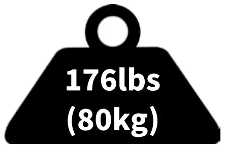 | DO NOT EXCEED WEIGHT CAPACITY. Failure to do so may result in serious injury |
TOOLS NEEDED | |
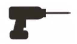 | 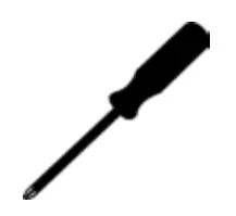 |
ASSEMBLY STEPS
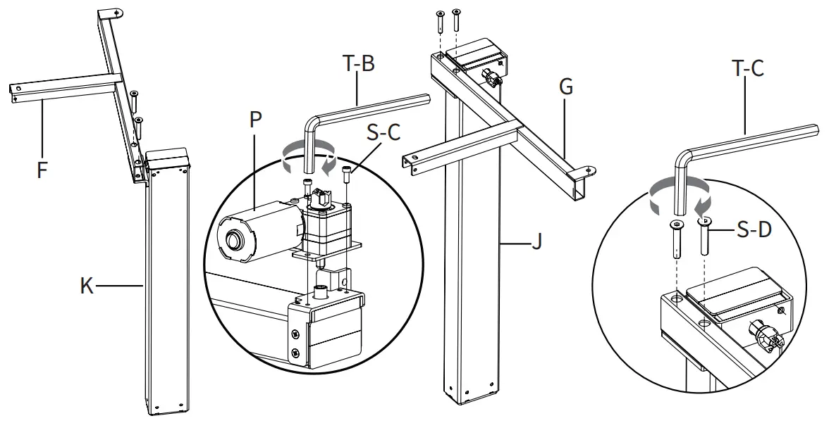
STEP 1
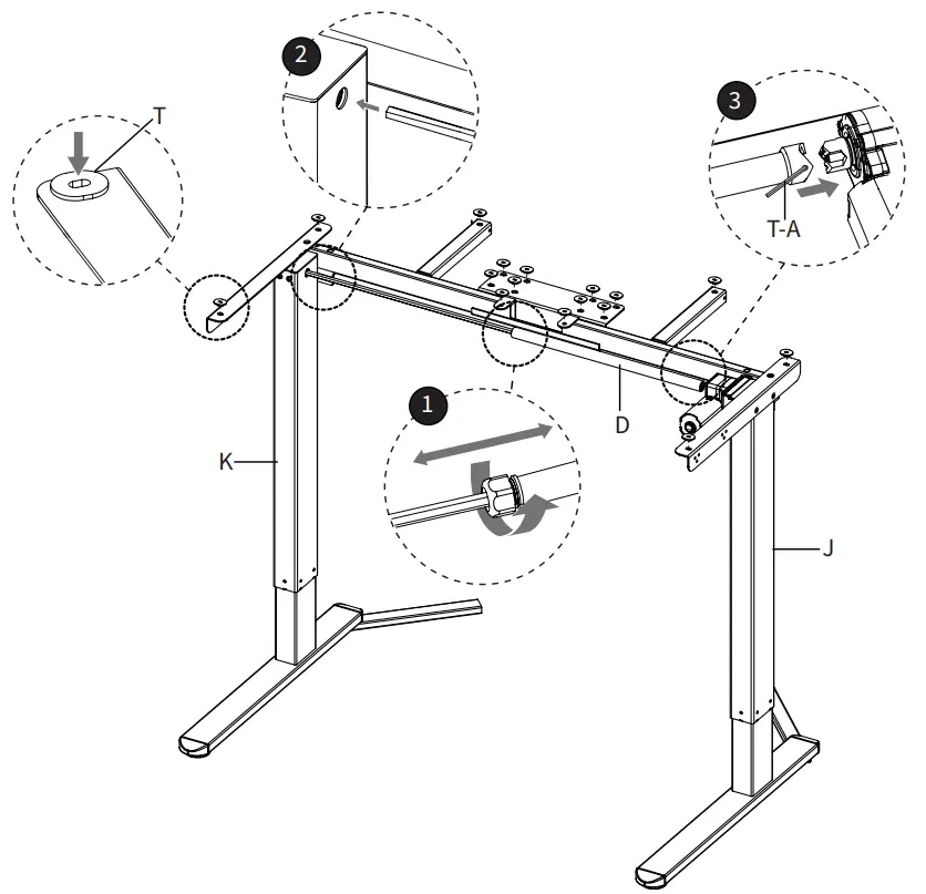
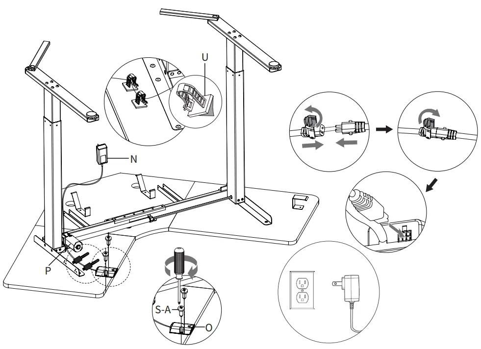
Assemble Left Crossbar (F) to Left Leg (K) and Right Crossbar (G) to Right Leg (J) using M8x47mm Screws (S-D) and 5mm Allen Wrench (T-C). Secure Motor (P) to Right Leg (J) using M5x12mm Screws (S-C) and 4mm Allen Wrench (T-B).
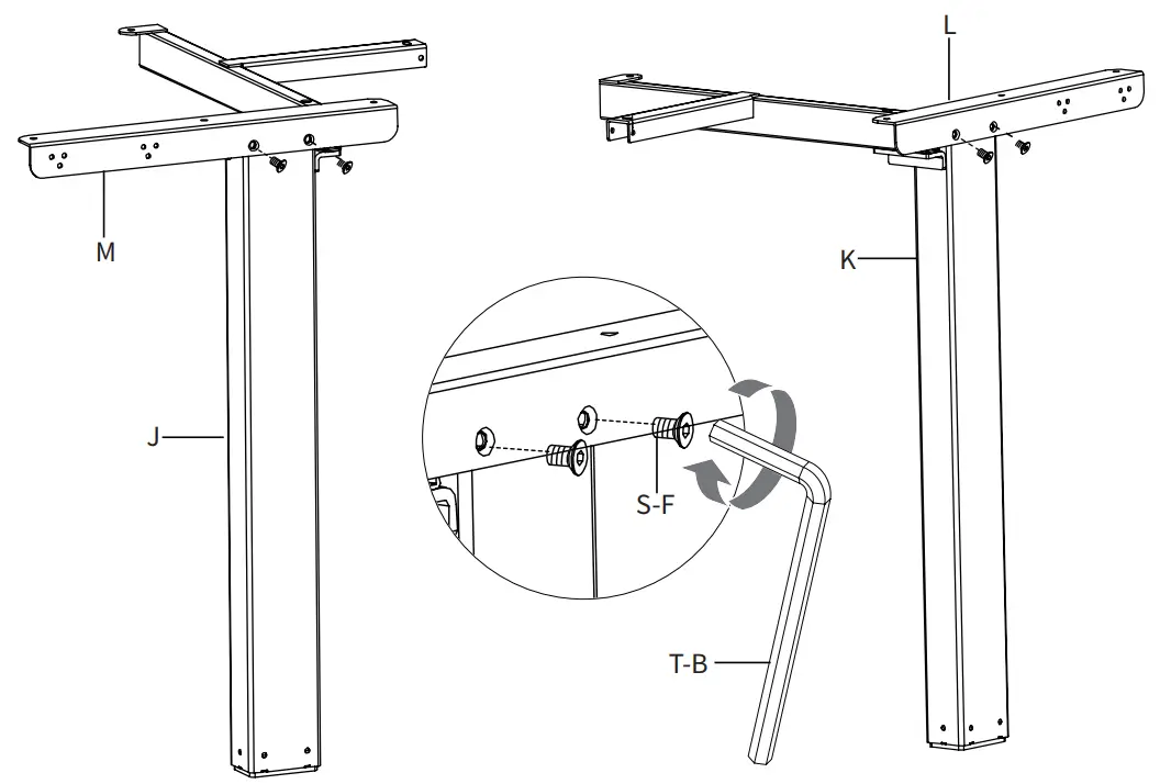
STEP 2
Mount Left Side Bracket (L) to Left Leg (K) and Right Side Bracket (M) to Right Leg (J) using M6x10mm Screws (S-F) and 4mm Allen Wrench (T-B).
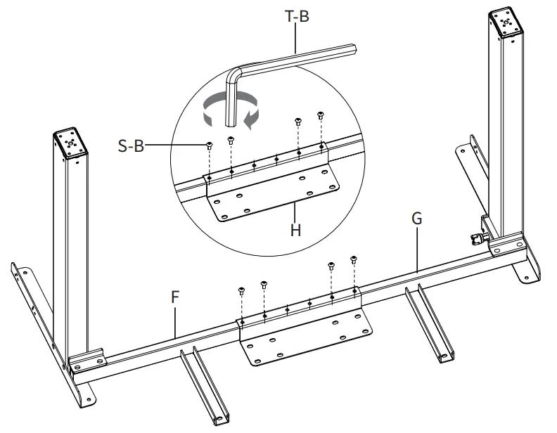
STEP 3
Assemble Left Crossbar (F) and Right Crossbar (G) with Crossbar Connector (H) using M6x12mm Screws (S-B) and 4mm Allen Wrench (T-B).
STEP 4
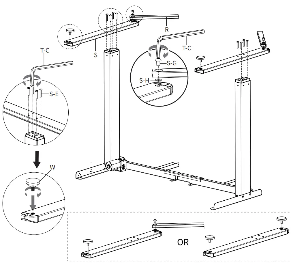
Secure Feet (S) to the frame assembly using M6x35mm Screws (S-E) and 5mm Allen Wrench (T-C). Screw Foot Pads (W) into Feet (S). For added stability, Foot Extensions (R) can be added to the back of Feet (S) with M8x12 Screws (S-G) and Washers (S-H). Tighten using 5mm Allen Wrench (T-C).
STEP 5
Insert Anti-Vibration Pads (T) to the frame assembly. Loosen the nut on Sync Rod (D) and insert the hex rod end into Left Leg (K). While holding the hex end, pull the larger rod out until the connector engages with Right Leg (J). Tighten the set screw on Sync Rod (D) using 2mm Allen Wrench (T-A), then tighten the nut.
STEP 6
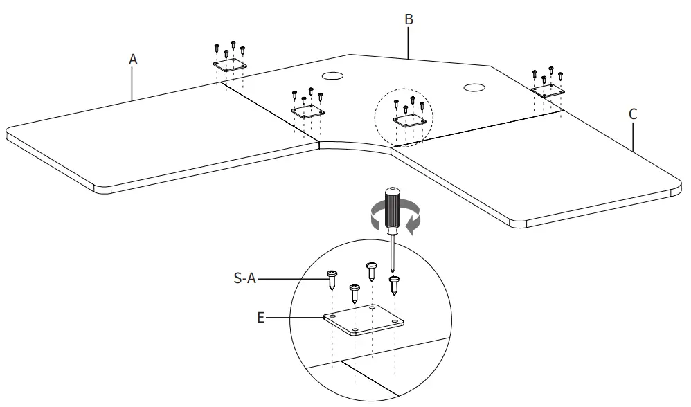
Place Left Panel (A), Middle Panel (B) and Right Panel (C) upside down on a flat surface. Mount Connecting Plates (E) with M5x16 Screws (S-A) and a Phillips screwdriver.
STEP 7
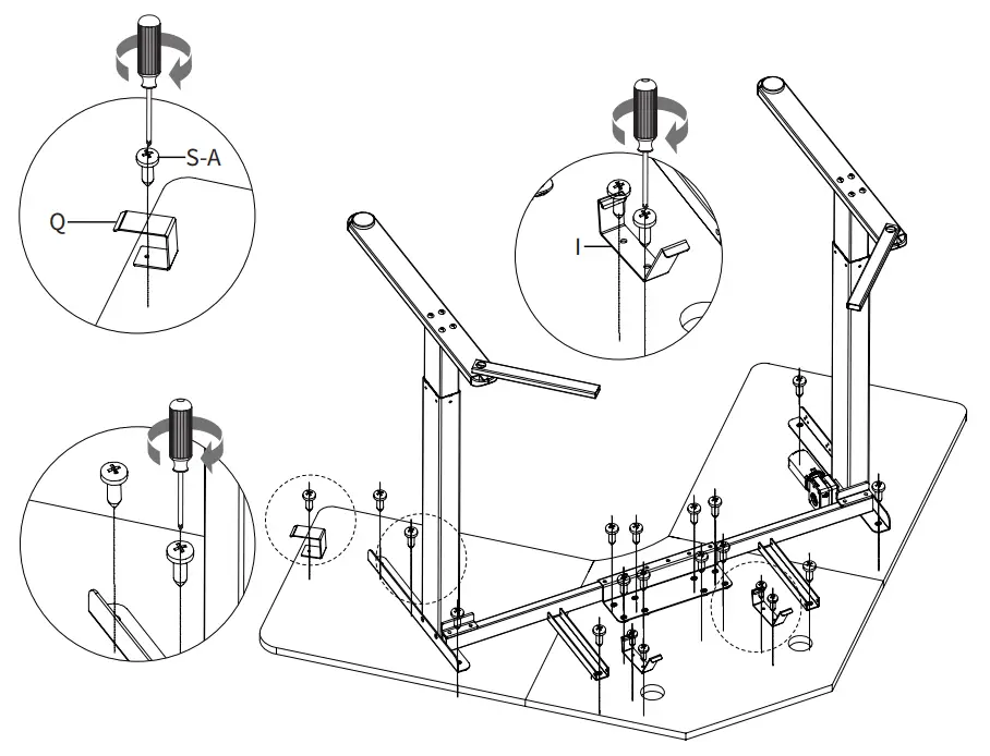
Secure the frame along with Hook (Q) and the brackets from Shelf (I) to the desktop assembly using M5x16mm Screws (S-A) and a Phillips screwdriver.
STEP 8
Connect AC Adapter (N) and Control Panel (O) to Motor (P). Secure Control Panel (O) to the desktop using M5x16mm Screws (S-A) and a Phillips screwdriver, then organize cables using Cable Clips (U). Plug AC Adapter (N) into a wall outlet.
STEP 9
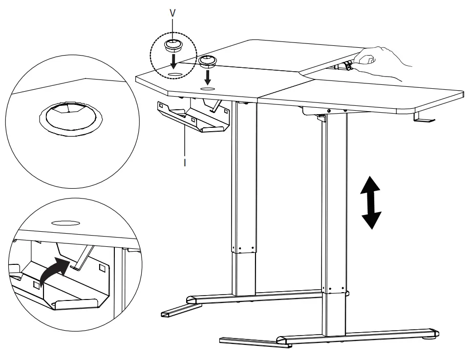
Insert Cable Management Covers (V) into the desktop. Connect Shelf (I) to the brackets. Refer to the controller manual for operation.
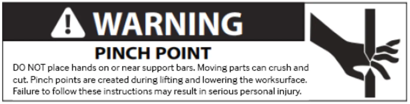
CAUTION!
Do not exceed desk weight limit. | Keep area of vertical motion free of obstacles. |
Keep weight on desk balanced for correct operation and longer life of components. | Leave enough slack in cables to allow for full range of vertical motion. |
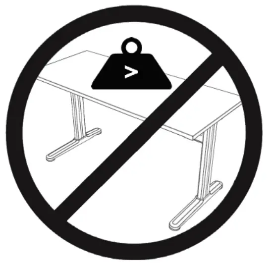
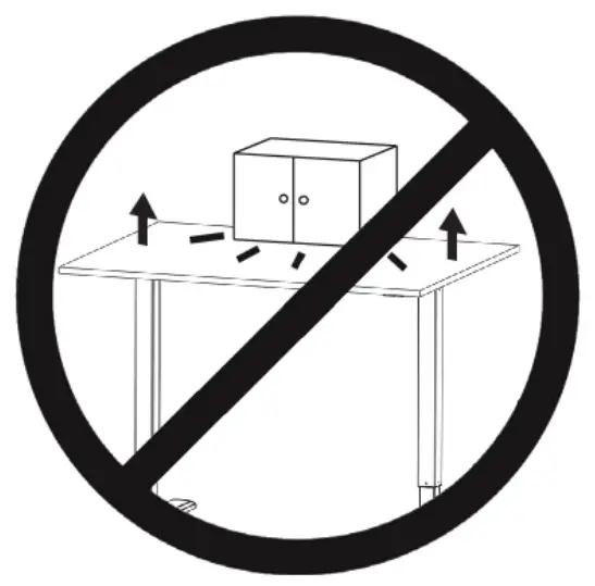
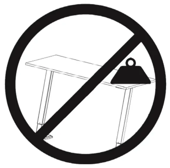
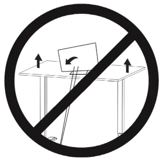
Failure to follow these instructions may result in property damage and/or personal injury.
SKU: DESK-E1L94B
 | Scan the QR code with your mobile device or follow the link for helpful videos and specifications related to this product. Instruction Manual https://vivo-us.com/products/desk-e1l94b |
CUSTOMER SUPPORT
 Love your new VIVO setup and want to share?
Tag us in your photo! @vivo_us
GET IN TOUCH | Open Monday – Friday 7:00am – 7:00pm CST,
our dedicated support team can offer immediate assistance with rapid response times. If any parts are received damaged or defective, please contact us. We are happy to replace parts to ensure you have a fully functioning product.
 309-278-5303 309-278-5303 | AVG. RESOLUTION TIME (within office hrs): 5M 4S |
 www.vivo-us.com www.vivo-us.comChat live with an agent! | AVG. RESOLUTION TIME (within office hrs): < 15 M |
 [email protected] [email protected] | AVG. RESPONSE TIME (within office hrs): 1HR 8M
|
FOR MORE VIVO PRODUCTS, CHECK OUT OUR WEBSITE AT: www.vivo-us.com | |