Danfoss 089 0879 Intelligent Purging System Ammonia
Legal notice
This product information is a part of the documentation for the Danfoss scope of delivery and serves as product presentation and customer advisory service. It contains important information and technical data regarding the product. This product information should be supplemented with the information about the industrial safety and health related regulations at the site of installation of the product. The regulations vary from place to place as a result of the statutory regulations applicable at the site of installation and are therefore not considered in this product information. In addition to this product information and the accident prevention regulations applicable for the respective country and area where the product is used, the technical regulations for safe and professional work must also be observed. This product information has been written in good faith. However, Danfoss cannot be held responsible for any errors that this document may contain or for their consequences. Danfoss reserves the right to make technical changes during the course of further development of the equipment covered by this product information. Illustrations and drawings in this product information are simplified representations. As a result of the improvements and changes, it is possible that the illustrations do not exactly match the current development status. The technical data and dimensions are subject to change. No claims will be accepted on the basis of them.
EU DECLARATION OF CONFORMITY
Danfoss A/S Refrigeration & Air Conditioning Controls
declares under our sole responsibility that the
Product category: Intelligent Purger System (Air Purger)
Type designation(s): IPS 8 Covered by this declaration is in conformity with the following directive(s), standard(s) or other normative document(s), provided that the product is used in accordance with our instructions.
Machine Directive 2006/42/EC
EN 378-2:2016 Refrigerating systems and heat pumps – Safety and environmental requirements – Part 2: Design, construction, testing, marking and documentation IEC 60204-1:2018 Safety requirements for electrical equipment for measurement, control and laboratory use – Part 1: General requirements
Pressure Equipment Directive 2014/68/EU (PED)
EN 378-2:2016 Refrigerating systems and heat pumps – Safety and environmental requirements – Part 2: Design, construction, testing, marking and documentation Ammonia side (R717): Category A4P3. Fluid group: 1. PS = 40 bar. TS: -40 ˜C to 60 ˜C R452A side: Category 1. Fluid group: 2. PS = 28 bar. TS: -40 ˜C to 60 ˜C Ambient temperature: -10 ˜C to 43 ˜C
Electromagnetic Compatibility Directive 2014/30/EU (EMC)
- IEC 61000-6-2 Electromagnetic compatibility (EMC) – Part 6-2: Generic standards – Immunity standard for industrial environments (IEC77/488/CDV:2015)
- EN 61000-6-4 Electromagnetic compatibiliy (EMC) – Part 6-4: Generic standards – Emission standard for industrial environments
Note: EMC test performed with cable length < 30m.
Danfoss only vouches for the correctness of the English version of this declaration. In the event of the declaration being translated into any other language, the translator concerned shall be liable for the correctness of the translation
- ID No: 084R9456
- Revision No: AA
Technical data
| Supply voltage for: IPS 8 Field1) connected solenoid coils | 230 V +/-10% AC, 1ph, 60Hz |
| Current | 5.7 A (max. 6.5 A) |
| Power consumption | max. 1.3 kW |
| Short-circuit current rating | Icc 10kA |
| Temperature range ambient | -10 °C to +43 °C (14 °F to 109 °F) |
| Temperature range transport/storage | -30 °C to +60 °C (-22 °F to 140 °F) |
| Enclosure | IP55 |
| Weight | max. 100 kg (221 lbs) |
| Dimensions (LxWxH) | 1051 x 441 x 703 mm (41.4 x 17.4 x 27.7 inches) |
| Purger refrigerant | R452A 900 gram (31.7 oz) |
| Max. operating pressure (PS) R452A | 28 bar (406 psi) |
| System refrigerant | R717 |
| Max. operating pressure R717 | 40 bar (580 psi) |
| Operating temperature R717 | -40 °C to +60 °C (-40 °F to 140 °F) |
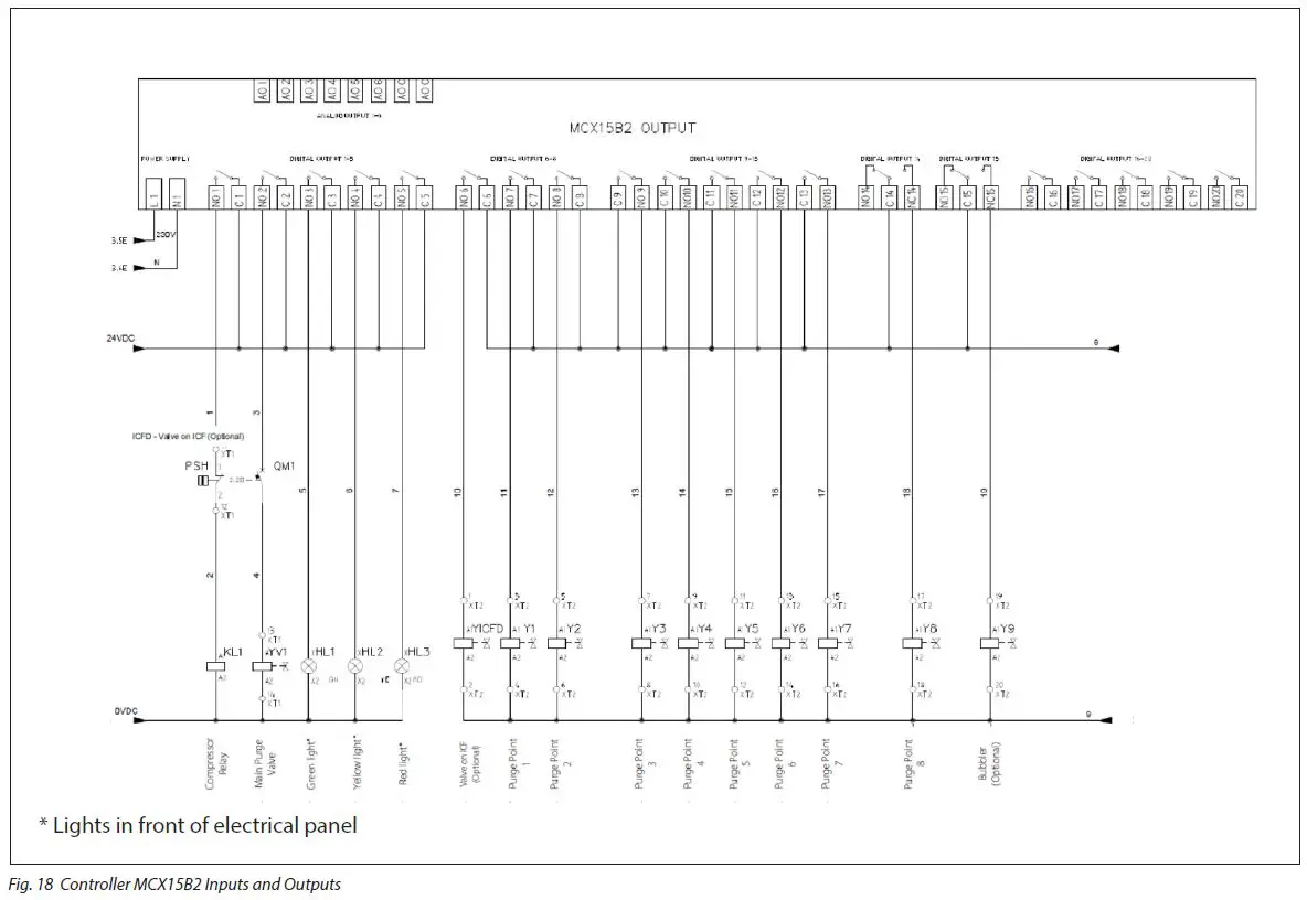
Description Field connected valves
- Digital Output, DO6 YV ICFD – Valve on ICF (Optional)
- Digital Output, DO7 Y1 Valve – Purge Point 1
- Digital Output, DO8 Y2 Valve – Purge Point 2
- Digital Output, DO9 Y3 Valve – Purge Point 3
- Digital Output, DO10 Y4 Valve – Purge Point 4
- Digital Output, DO11 Y5 Valve – Purge Point 5
- Digital Output, DO12 Y6 Valve – Purge Point 6
- Digital Output, DO13 Y7 Valve – Purge Point 7
- Digital Output, DO14 Y8 Valve – Purge Point 8
- Digital Output, DO15 Y9 Valve – Bubbler (Optional) / General Alarm (Optional)
Ordering
| Unit | Code number |
| Danfoss Intelligent Purging System IPS 8 unit | 084H5002 |
| Accessories/Spare parts | Accessory (Not included with IPS) | Spare parts for service (Built-into IPS) | Code |
| Flange blind blank incl Bolts, nuts and Gaskets* | x | 084H5053 | |
| SV3 Float Valve | x | 027B2023 | |
| ICF 15-4 solenoid, DIN Butt weld 15mm ½ inch | x | 027L4543 | |
| ICF 15-4 solenoid, ANSI Socket weld 15mm ½ inch | x | 027L4538 | |
| ICF 15-4 solenoid, ANSI Butt weld 15mm ½ inch | x | 027L4602 | |
| Welding Flange incl Bolts, nuts and Gaskets | x | 084H5061 | |
| Repair kit for Main Purge Valve (Armature, tube, Sealing, Orifice, Filter insert). See Fig. 1, Item 16 | x | x | 084H5051 |
| Solenoid coil, 24V DC for Main Purge Valve. See Fig. 1, Item 16 | x | x | 018F6757 |
| PSU, 24V DC – optional for powering purge points | x | x | 080Z0055 |
| Restrictor, in purge line after Main Purge Valve. See Fig. 1, Item 18 and Fig. 13. | x | 084H5054 | |
| Compressor Cranck case heater | x | 084H5058 | |
| Condenser coil assy incl screws | x | 084H5059 | |
| Fan motor for condenser Incl fan grid and screws | x | 084H5060 | |
| Extraction Fan | x | 084H5056 | |
| Air grid with filter (2 pieces) | x | 084H5057 | |
| Pre-programmed MCX15B2 with application SW included | x | 084H5067 | |
| Pressure transmitter evaporator, soldered (AKS 32R) | x | 060G3552 | |
| Compressor including Start relay box and Start and Run Capacitor | x | 123B2156 | |
| Compressor Hi-temp sensor | x | 084N2003 | |
| Expansion valve, R452A | x | 068U3881 | |
| Sight glass | x | 014-0191 | |
| Pressure transmitter – R717, Threaded, AKS2050 | x | 060G5750 | |
| Thermostat for crankcase heater control | x | 060L111166 | |
| Temperature sensor – R717, AKS 21M | x | 084N2003 | |
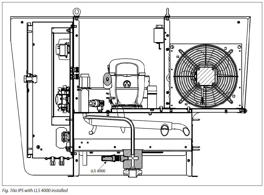
| LLS 4000 liquid level switch G 3/4” ** | x | 084H6001 | |
| Pressure switch for Fan | x | Contact Danfoss | |
| Pressure safety switch | x | Contact Danfoss |
- For closing system flange during system pressure testing
- See Fig. 1 and Fig. 10a
Introduction
The Danfoss Intelligent Purging System (IPS 8) is a stand-alone, self-contained purging unit designed to remove non-condensable gases (NC gases = air and other unwanted foreign gases) from industrial ammonia refrigeration systems. The IPS control can handle up to 8 purge points automatically. The ingress of NC gases into a refrigeration system is inevitable, regardless of the refrigerant, pressures, or temperatures. NC gases in the system will result in a decrease in system efficiency, both in terms of an increase in power consumption and reduced cooling capacity.
Due to having a different density than ammonia, the ingressed air will accumulate in specific areas of the system, where it can be removed using the Danfoss IPS 8. The accumulation areas are identified in the Connection locations section, along with recommended connection principles. The purger unit is an electronically controlled, self-contained R452A refrigerant system that runs independent of the main ammonia system and with only one flange connection to the ammonia plant. The flanged opening allows the ammonia gas/NC gas mix access to the purger’s heat exchanger, where it is split into ammonia condensate and NC gases. The ammonia condensate is returned by gravity to the main plant, while the NC gases are purged to the atmosphere through e.g. a water bath. Through the flanged opening, the purger unit has access to the parameters from the ammonia plant required for full electronic control. The unit runs automatically in 24-hour cycles, checking for the presence of NC gases and, if present, removes the NC gases. To regain and retain the design capacity of the main ammonia system and prevent future air accumulation, it is highly recommended to install the Danfoss IPS 8.
Features
- State-of-the-art electronically controlled unit based on the Danfoss MCX controller platform
- Reduced power consumption of the ammonia plant
- Automatic purging response to NC gases in the refrigeration system
- Continuous and smart monitoring of differential pressure between the system refrigerant and the purger’s refrigerant
- Smart purging that minimizes refrigerant (ammonia) release to the environment
- Self-contained unit operation, which functions independently from the main plant
- An operation log for easy purging cycle data monitoring
- Industry-standard Modbus RTU communication for remote monitoring and system integration
- Reduced purging unit power consumption compared to other units due to on-demand operation only
- Load scheme to identify which purge point is removing most NCC
- Prepared to manage/control Bubbler
- Option to install LLS 4000 to protect IPS for high column of ammonia liquid
- Self-diagnostics for both unit and system operation to shut down in the event of malfunctions
- Cost-effective installation with few mechanical and electrical connections
- A fully brazed and leak-tested R452A cooling system, minimizing leakage risks
- A plug-and-play stand-alone design, which simplifies installation and commissioning while reducing potential errors
- No need for advanced settings
- A compact and easy-to-handle design
- IPS carry a registered patent
Working principle
The Danfoss IPS 8 is factory-tested and ready to use in ammonia plants with a condenser pressure of more than 6,5 bar (94 psi). The purger is charged with 900 gram (31.7 oz) of R452A. Only 1 mechanical connection is needed for the purger (see fig. 1). The flow of ammonia/NC gases from the main plant is done through the flange for ammonia (see 13 in Fig. 1 below), while the NC gas purge is done through the blow-off pipe after the purge restrictor (18). Through the flange for ammonia (13), a mixture of ammonia gas and NC gases enters the heat exchanger (12) part of the purger. The ammonia gas/NC gas mix is cooled down below the condensing temperature of the ammonia by the R452A circuit. At this point, ammonia gas condenses and returns by gravity to the ammonia plant whereas the NC gases accumulate in the heat exchanger (12) for subsequent purging. By condensing the ammonia gas, a new ammonia/NC gases mix is naturally pulled through. This new mix is separated through a continuous process. As the NC gas concentration in the heat exchanger (12) increases, the R452A heat exchanger pressure and temperature will simultaneously decrease. The controller continuously monitors the R452A heat exchanger pressure as well as ammonia pressure and temperature. When the R452A pressure reaches a predefined pressure difference when compared with the ammonia pressure (temperature) it prepares to purge the NC gases through the solenoid valve (16). The blow-off is activated by the solenoid (16) and through appropriate piping/hosing, should be led into a water bath. This process is recommended to retain small amounts of ammonia (see Installation section).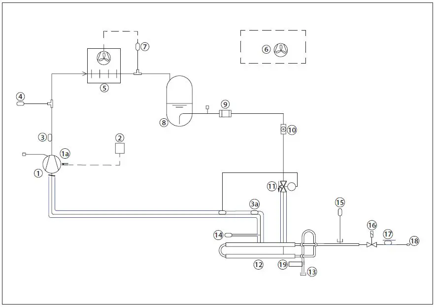
Fig. 1 – Purger R452A lay-out
| 1 | Compressor (900 gram (31.7 oz) R452A) controlled via Digital Output, DO1 | 11 | Expansion valve, R452A |
| 1a | Compressor Cranck case heater | 12 | Heat exchanger Ammonia/R452A |
| 2 | Thermostat for crankcase heater control | 13 | Welding Flange |
| 3 | Discharge temp sensor R452A via Analog Input AI3, Pt 1000 | 14 | Pressure transmitter R452A. Measured via via Analog Input AI1, Pressure transmitter, AKS 32R |
| 3a | Suction temperature sensor R452A via Analog Input AI4, Pt 1000 | 15 | Pressure transmitter R717. Measured via Analog Input, AI2, Pressure transmitter, AKS 2050 |
| 4 | Pressure safety switch | 16 | Main Purge Valve controlled via Digital Output, DO2 |
| 5 | Condenser | 17 | NC temperature sensor R717. Measured via Analog Input, AI5, Pt1000 |
| 6 | Extraction fan | 18 | Restrictor, purge line |
| 7 | Pressure switch for Condenser Fan | 19 | LLS 4000 Liquid Level Switch. Accessory. Not included with standard IPS |
| 8 | Receiver | ||
| 9 | Filter | ||
| 10 | Sight glass |
Working cycle
The Danfoss IPS 8 operates in 24-hour cycles, of which 45 minutes are dedicated to an R452A pull down. At power on, the pull down is initiated immediately. If no NC gases are detected during the 40 minute pull down, the system will close the solenoid valve at purge point 1 and open the solenoid valve at point 2. After a cycle time of 24 hours/N (Number of purge points), the compressor will pull down again condensing the ammonia. After 24 hours, all purge points have been vented one time. To identify NC gases, the controller utilizes upper and lower thresholds for R452A evaporating temperature. If, during pull down, the temperature continues decreasing and the lower threshold is passed, the controller considers this to be a high concentration of NC gases and opens the purge solenoid valve. The purge valve will stay open until sufficient condensing ammonia is present to lift the R452A evaporating temperature above the upper threshold. The compressor will continue running and if the temperature again decreases below the lower threshold, a new purge will be performed. This process will be repeated until the R452A heat exchanger temperature stays above the lower threshold for >40 minutes following the previous closure of the purge valve.
| Label ID | Parameter Name | Description and selection options | Factory setting |
| CM3 | PDT | Pull down time Pull down time of compressor | 40 min |
| CM4 | CST | Compressor start time See Fig. 2 for details | 1440 min (24 h) |
| VA5 | PLT | Endless purging max time Max time for endless purging on one point. When the time has expired, IPS will go to next Purge Point (PP) | 24 h |
See complete Parameter List – Table 01
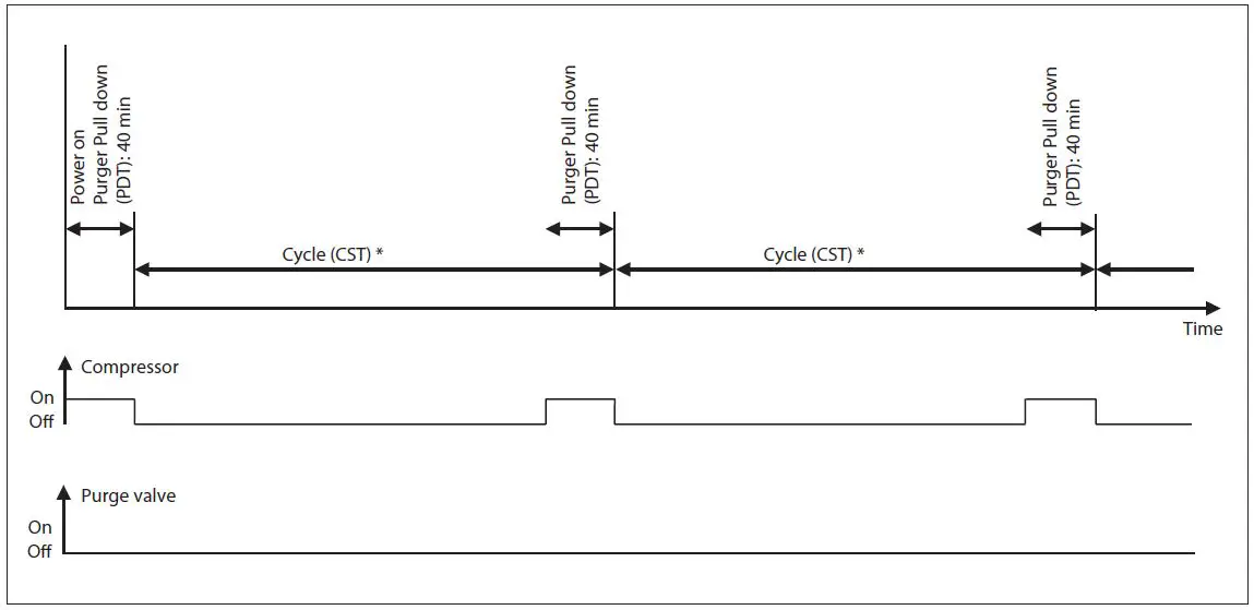
Fig. 2 – Power on & Cycle at no NC gases present: CST (compressor start time) and PDT (pull down time) are configurable * Cycle (CST) = 24 hours/N (number of purge points)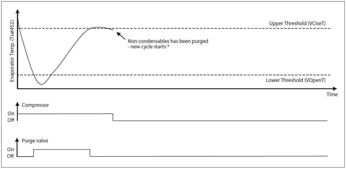
Fig. 3 – Purging procedure – Low R452A evap. temperature detected during PDT: Thresholds are configurable If low evaporator temperature is detected (passing lower threshold), the purging procedure will be repeated immediately
Air traps
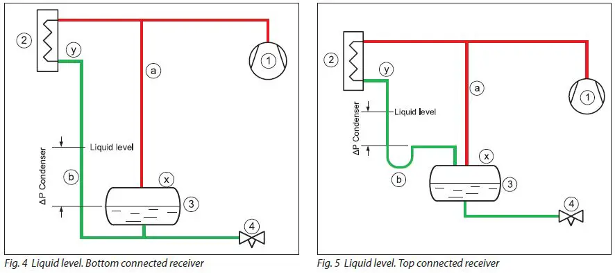
For systems with low pressure liquid level control, the correct condenser/ receiver installation is as shown in Fig. 4 and Fig. 5. The discharge gas from the compressor (1) is led to the condenser (2) where it is condensed. The receiver (3) holds the liquid until there is a demand for liquid from the LP side, e.g., until the expansion valve (4) opens. If the expansion valve is closed, the liquid condensed in the condenser will need to be stored in the receiver and the level will increase. To ensure a free flow to the receiver, the gas must be allowed to leave the receiver; this process is accomplished through the pressure equalizing line (a). The pressure equalizing line makes the pressure in the receiver the same as in the compressor discharge line. The pressure in the condenser outlet is lower due to the pressure loss in the condenser. Since the condenser outlet pressure is lower than in the receiver, it is therefore necessary to mount the condenser higher than the receiver and allow for a higher liquid level in the piping between the condenser and the receiver (b). The liquid column in the line (b) compensates for the pressure difference between the condenser outlet and the receiver. Fig. 4 shows the liquid connection at the bottom of the receiver. If the liquid from the condenser is connected to the top of the receiver (Fig. 5), a slightly different arrangement must be made. The liquid line (b) from the condenser to the receiver will need to have a goose neck/liquid trap to ensure that the liquid column is actually established. As air is heavier than ammonia gas, the air will collect in two locations in this type of installation: On top of the liquid in the receiver (x) and/or on top of the liquid in the drop leg from the condenser (y).
Connection locations
- Air purger installation in a low-pressure liquid level controlled installation
The correct locations for the air purger to be connected to the ammonia plant are: (See Fig. 6 and Fig. 7)
- on top of the receiver or
- on top of the liquid in the drop leg from the condenser.
The air purger (5) is connected to the two purge points through solenoid valves (px and py). Note that only one solenoid should be open at any given time, otherwise the liquid column in the condenser will be short-circuited. The air purger must have its own liquid return drop leg (c) connected in parallel with the condenser’s drop legs (b). When the purger is connected to the receiver i.e. solenoid (px) open, the liquid level in the air purgers drop leg (c) will be equal to the receiver liquid level (3); when the purger is connected to the condenser outlet i.e. solenoid (py) open, the liquid level will be equal to the liquid level in the condenser drop leg (b).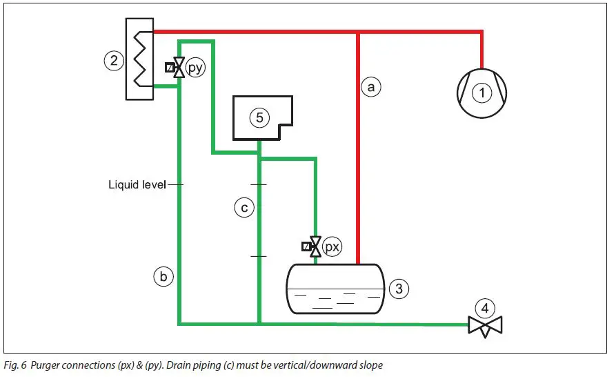
Fig. 6 Purger connections (px) & (py). Drain piping (c) must be vertical/downward slope
Alternatively, the air purger draining of liquid can be achieved effectively through an HP float valve (6) to the low pressure side (see Fig. 7).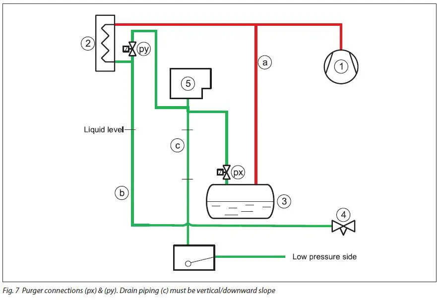
Connection locations (continued)
- Air purger installation in a high-pressure liquid level controlled installation
For systems with a high-pressure liquid level control, the air will collect in the float valve (3). (See Fig. 8). The compressor (1) supplies high-pressure gas to the condenser (2), where it is condensed. The float valve (3) will flash any liquid back to the LP side. The air purger (5) must be connected to the float valve through a solenoid valve (pv).The ammonia liquid condensed in the air purger must be drained through drain pipe (c) to the LP side via a float valve (6).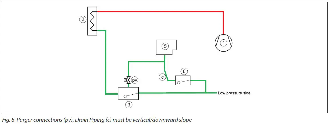
General
The air purger must always be mounted above the highest liquid level to be able to drain the ammonia condensed in it. Otherwise, the air purger can flood and potentially purge ammonia liquid. The purger liquid return leg (c) must always be mounted vertically or at minimum, with a downward slope. The solenoid valves at the connection points must never be activated at the same time. Finalize purging at one location before switching to the next.
WARNING !
Follow the installation guide strictly during Purger installation. Install the Purger unit in a location where the bottom flange level and any gas inlet connection level is above any possible ammonia liquid level. Liquid drain piping from the purger must always have a downward slope. Install a shut off valve close to the bottom flange entrance to enable removal of the unit and closing for high pressure ammonia gas. Connect proper resistant piping to the purging outlet pipe and ensure the purged non-condensables are discharged into a water bath of max. 200 liter.
Connection points
Multi-point purging
As factory default, the Danfoss IPS 8 is configured to manage up to 8 purge points. (Multi-point purging. See Fig. 10). The actual amount of purge points connected needs to be setup in the MCX controller after power-up. The parameter in question for entering the actual number of purge point: V10, Max_PP (See Table 3). Single point purging setup is possible (See Fig. 09 -no purge solenoid valves). For single point purging the parameter in question for entering the actual number of purge point: V10, Max_PP must be set to 1 (See Table 3). Both power and control wiring of the installed solenoid valves coils should take place prior to first power up.
NEVER HAVE MORE THAN 1 PURGE POINT OPEN AT A TIME.
Always close one purge valve before opening the next. This is done by turning the purger unit power on and entering the number of actual purge points (V10, Max_PP) in the program. See section “Programming/configuration”.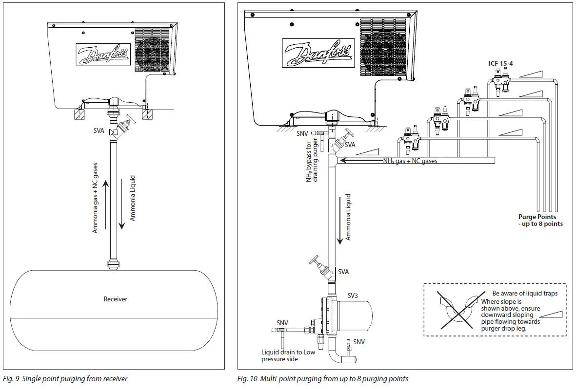
- See Installation guide for Danfoss floats:
- Type SV3 – Lit.No. : AN149486432996
- Type ICFD used in ICFD – Lit.No. : AN250286497620
- See Installation guide for LLS 4000 Liquid Level Switch: AN317523977313
Installation
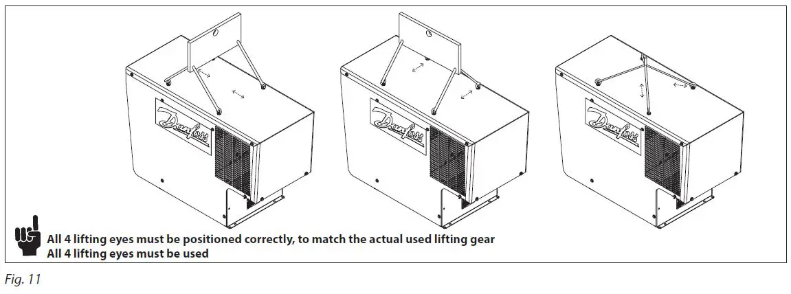
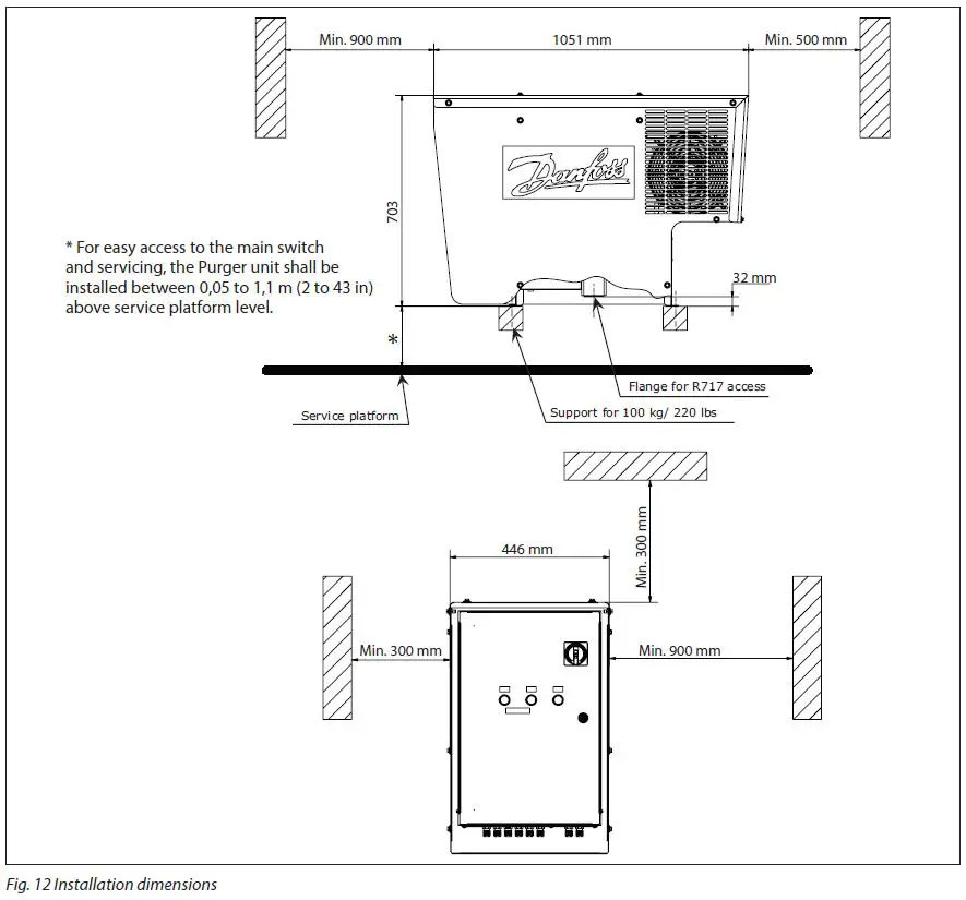
The Danfoss IPS 8 must be installed in accordance with locations recommended in the Connection locations and Connection points sections of this document. The unit has a protection rating of IP55 and may be installed outside, in ambient temperature ranges from from -10 °C to 43 °C / 14 °F to 109 °F). Avoid installation in direct sunlight as this may lead to excessive sunlight exposure and ambient temperatures above allowed limits. For ambient temperatures below -10 °C (14 °F) the air purger must be installed in a heated and ventilated area. The unit must be installed in a non- ATEX atmosphere as the purger unit is not explosion proof. The purger unit should be kept in an upright position at all times – from receipt to final installation.Use all 4 lifting eyes and suitable lifting gear during installation (unit weight = 100 kg/220 lbs). Install the unit on an even horizontal base 0.05 to 1.1 meter (2 to 43 in) above a service platform with sufficient support and allowing the purger subframe to be bolted to the support (see example in Fig. 12). Maintain recommended distances in all directions (Fig. 12) to allow fan cooling and servicing.
- Always leave the unit off for at least 12 hours from finished installation to first time power up.
- It is important that the support construction is level to ensure the internal liquid trap is properly filled. Angle to horizontal < 2 degrees
Lifting Procedure
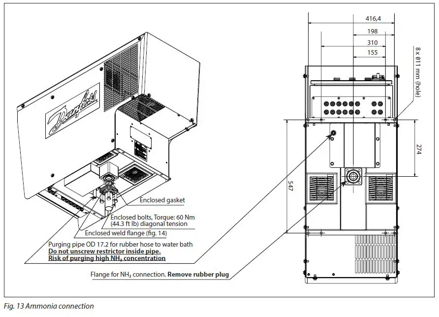
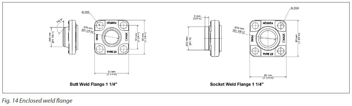
- Prepare the ammonia pipework with the weld flange according to Fig. 13 and Fig. 14. The main/drain piping should never be smaller than inner diameter Ø37 mm (1.5 in).
- Complete the supporting structure able to carry 100 kg (221 lbs).
- Lift the purger into position using the lifting eyes on each side of the purger’s cabinet. Remove the rubber plug from the flange opening. See Fig. 13.
- Connect the weld flange with the purger flange using the enclosed flat gasket and tighten the supplied 4 bolts diagonally to a torque of 60 Nm (44.3 ft-lb).
- Insert 4 bolts (not supplied) through the purger frame and the support construction and tighten.
- Perform a leak test to ensure an airtight connection.
- In the event the purger unit needs to be dismantled please contact Danfoss for instructions.
- Correctly install a suitable pipe/hose from the purge solenoid valve for blow-off of NC gases in accordance with local or national regulations.
- Prepare an outside water tank with a maximum of 200 liters (53 gal.) and ensure the piping allows the purged gas to be immersed in the water.
- Regularly check the pH level of the tank’s contents.
- The pH level should never exceed 12.6. Otherwise the water content must be renewed.
- Dispose of concentrated waste water in accordance with to local/national regulations.
Note: Prior to replacing the water in the water tank ensure that the purger is switched off and the shut off valve at the flanged purger inlet is closed. Leave the unit in this condition for a period to allow the remaining gas in the piping to be dissolved/released.
Watch out for bubbles. Establish a procedure for regular checking the pH level and bubble pattern. If continuous bubbles are observed in the water tank during ‘‘stand by” (Green light indicator) in normal operation, one or more of the purge solenoid valves needs repair or replacement.
Electrical wiring
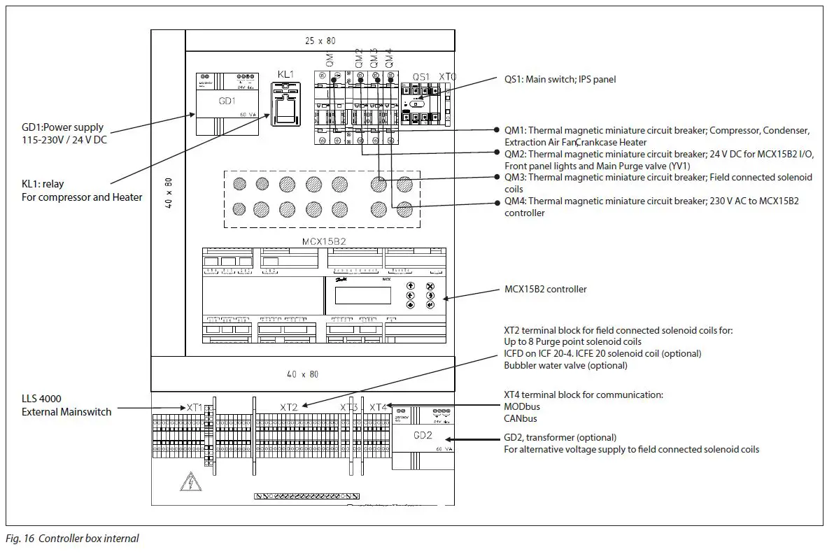
- The internal wiring of the purger is done at the factory. Only the electrical wiring for the main power supply, the purge point solenoids and optional bus communication needs wiring on site.
- It is highly recommended that all external cables coming from the IPS 8 to the power supply and to all purge point solenoids are protected by metallic pipes.
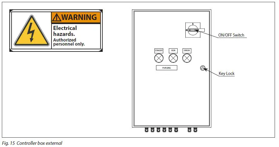
Controller box cover can only be opened at key unlock and with the main switch off.
Note: Authorized personel only
Electrical wiring (continued)
Light Indicators
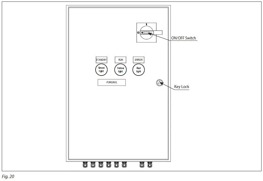
| Lights ON | Status | Compressor ON | Compressor OFF | Purge Valve ON | Purge Valve OFF | Alarm |
| Green | Stand by | x | x | |||
| Yellow | Run | x | x | |||
| Green & Yellow | Purging | x | x | |||
| Green & Yellow & Red | Uninterupted Long time purging (> 150 h) | x | x* | |||
| Red | Occurs when: Check list of alarms description | (x**) | x** | x |
- The purger continuous purging until max running period (default 160 h) is reached and the purger compressor will stop
- The purger compressor stops when alarm occurs
Quick Startup
For the fastest possible system configuration after connecting all purge points to the IPS and following first power up of the IPS, follow these simple instructions:
- Navigate from the Main Menu to Login
- Enter password ‘200’.
- Choose ‘Parameters’.
- Choose ‘Unit Config’
- Choose ‘Valve Settings’
- Enter the amount of purge solenoid valves connected to the IPS.
Navigation – built in MCX controller
(Placed at the rear of the front panel door)
- After switching on the controller, a display window will momentarily show the actual software version, followed by the default main operating window shown in Fig. 26.
- While in operation mode, the Up/Down arrow buttons lead the user to the status windows described in Table 01 below.
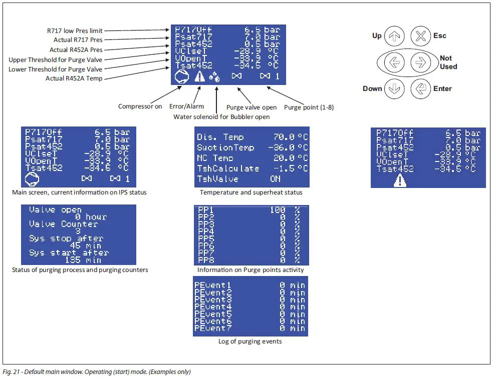
- By pressing
 the main menu will show up with the options below
Main menu navigation
| Label ID | Parameter Name | Description and selection options | Min. | Max. | Value/ Type | Unit | RW | MODBUS Register |
| StU | General > Setup | |||||||
|
y01 |
Main switch | Release the IPS for operation OFF: the IPS is forced out of operation ON: the controller released for operation. Observe if DI1, On/ Off – External Mainswitch must also be ON to release the IPS for operation |
0 |
1 |
0 – OFF | Enum 1 |
RW |
3001 |
|
y07 | Restore default parameters | Back factory settings No: Not active Yes: All parameters will be returned to factory default settings, and the alarm list will be cleared. The parameter will automatically be set back to ‘No’ when factory reset has finished (after a few seconds). |
0 |
1 |
0 – NO | Enum 2 |
RW |
3002 |
| SEr | General > Serial settings | |||||||
| SEr | Serial address (Modbus and CAN) | Enter ID adress of the controller Only relevant if connected to external equipment (like PLC) or other Danfoss equipment. | 1 | 100 | 1 | RW | 3006 | |
|
bAU |
Serial baudrate (Modbus) | Baudrate The system unit usually communicates with 38.400. 0=0 1=12 corresponds to 1200 2=24 corresponds to 2400 3=48 corresponds to 4800 4=96 corresponds to 9600 5=144 corresponds to 14400 6=192 corresponds to 192000 7=288 corresponds to 288000 8=384 corresponds to 38400 |
0 |
8 |
8 – 384 |
Enum 3 |
RW |
3007 |
| COM | Serial settings (Modbus) | Serial mode 0=8N1 1=8E1 2=8N2 | 0 | 2 | 1 – 8E1 | Enum 4 | RW | 3008 |
| ExP | General > Expansion settings | |||||||
|
Ex1 |
Enable expansion | Enable expansion of extra purge point Panel with MCX contoller to purge extra purge points, in addition to the 8 purge points at the main IPS No: Disabel Yes: Enable |
0 |
1 |
0 – NO | Enum 2 |
RW |
3013 |
| Ex2 | Expansion address | Expansion adress of MCX controller Located in external panel (outside main IPS electrical panel) | 0 | 255 | 125 | RW | 3014 | |
| CMP | Unit config > Compressor | |||||||
| CM3 | PDT | Pull down time Pull down time of compressor | 1 | CM4 | 40 | min | RW | 3016 |
| CM4 | CST | Compressor start time See Fig. 2 for details | 180 | 2000 | 1440 | min | RW | 3017 |
| VA5 | PLT | Endless purging max time Max time for endless purging on one point. When the time has expired, IPS will go to next Purge Point (PP) | 2 | 768 | 24 | h | RW | 3018 |
| VAL | Unit config > Valve settings | |||||||
| VA2 | DeltaTValveOFF | Temperatue difference Open/Close Main Purge valve Temperature diffrence between opening and and closing setpoint of main Purge valve on DO2 | 2.0 | 10.0 | 5.0 | RW | 3019 | |
| V10 | Max_PP | Max number of Purge points Enter number of purge point (valves) connected to IPS | 1 | 16 | 8 | RW | 3026 | |
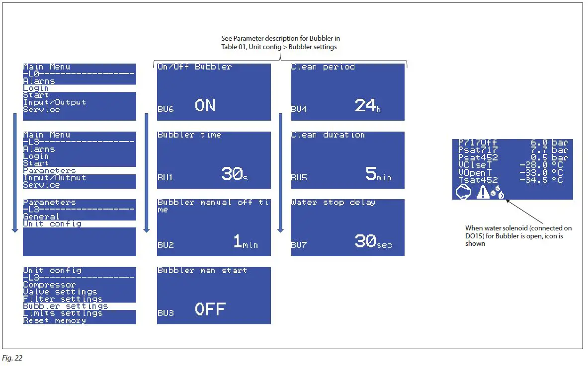
| BUB | Unit config > Bubbler settings | |||||||
|
BU6 |
On/Off Bubbler | Bubbler connected? Select if a bubbler is connected and water valve (on DO15)will be controlled OFF: Function disabled ON: Function enabled |
0 |
1 |
0 – OFF | Enum 1 |
RW |
3032 |
| BU1 | Bubbler time | Bubbler time Time for water valve to open for adding water to bubbler after start of compressor | 0 | 720 | 30 | s | RW | 3033 |
| BU2 | Bubbler manual off time | Bubbler manual off time Only active if BU3, Bubbler man start=ON Se description for BU3, Bubbler man start | 0 | 100 | 1 | min | RW | 3034 |
|
BU3 |
Bubbler man start | Manual opening of water valve for bubbler Select manual opening of water valve – DO15 OFF: Function disabled ON: Function enabled. Water valve will be open for the time ,given by BU3, Bubbler man start, have expired and close again |
0 |
1 |
0 – OFF | Enum 1 |
RW |
3035 |
Human Machine Interface (HMI) is the interface between the IPS and the user. Here the key pad and the display on the MCX15B2
| Label ID | Parameter Name | Description and selection options | Min. | Max. | Value/ Type | Unit | RW | MODBUS Register |
| BU4 | Clean period | Bubbler cleaning program Setting of time between start cleaning of bubbler. Se description for BU5, Clean duration | 0 | 72 | 24 | h | RW | 3036 |
| BU5 | Clean duration | Bubbler cleaning program – duration Once the Cleaning start period, given by BU4, Clean period, has has passed, the water valve – DO15, will open until the time give by BU5, Clean duration has expired | 0 | 100 | 5 | min | RW | 3037 |
| BU7 | Water stop delay | Water stop delay Delay for closing water valve – DO15 after main purge valve – DO2 is closed | 0 | 360 | 30 | sec | RW | 3038 |
| LIM | Unit config > Limits settings | |||||||
| LI3 | BPLMin | Calibration Low Pressure tranmitter R452A. [bar] Minimum value | -1.0 | 25.0 | 0.1 | bar | RW | 3051 |
| F06 | BPLMin | Calibration Low Pressure tranmitter R452A. [psi] Minimum value | -14.5 | 362.6 | 1.4 | Psi | RW | 3052 |
| LI6 | BPHMax | Calibration of High Pressure tranmitter R717. Min [bar] Maximum value | -1.0 | 59.0 | 24.0 | bar | RW | 3057 |
| F09 | BPHMax | Calibration of High Pressure tranmitter R717. Min [psi] Maximum value | -14.5 | 855.7 | 348.0 | Psi | RW | 3058 |
|
CM1 |
Setpoint | Setpoint [bar] Minimum pressure at when the purging process will start. If the P717 pressure (AI2) – is lower than this setpoint, Purge point 1 will open, then Purge point 2 automaticly etc. Once purging a given Purge point and P717 pressure (AI2) – is higher than this setpoint, the cycle with compressor will start. See also V48, Setpoint_Out |
5.0 |
12.0 |
6.5 |
bar |
RW |
3061 |
|
F10 |
Setpoint | Setpoint [psi] Minimum pressure at when the purging process will start. If the P717 pressure (AI2) – is lower than this setpoint, Purge point 1 will open, then Purge point 2 automaticly etc. Once purging a given Purge point and P717 pressure (AI2) – is higher than this setpoint, the cycle with compressor will start. See also V48, Setpoint_Out |
41.0 |
174.0 |
94.2 |
Psi |
RW |
3062 |
| UNI | Service > Unit | |||||||
| UN1 | Unit sensor | Display unit 0:MET: Metric units – Celsius (°C) and Bar 1:IMP: Imperial units – Fahrenheit (°F) and psi | 0 | 1 | 0 – Metric | Enum 6 | RW | 3065 |
| LOG | Status var > MCX Design Hotspots | |||||||
| C01 | Reset Alarms | Reset Alarms | 0 | 2 | 0 | RW | 1859 | |
| V02 | SystemOnOff | System ON / OFF Status of both intermal and external mainswitch and internal main switch | -32768 | 32767 | 0 | Read | 8101 | |
| V03 | ValveStatus | Purge Valve status Startus of Main purge valve AKVA – DO2 | -32768 | 32767 | 0 | Read | 8102 | |
| V04 | CompressorStatus | Compressor Status Startus of Compressor operation – DO1 | -32768 | 32767 | 0 | Read | 8103 | |
| V06 | PressTotemp | Pressure to temperature Pressure form Low Pressure tranmitter R452A, AI1 calculated to temperature | -327.7 | 327.7 | 0.0 | Read | 8104 | |
| V07 | ValveCount | Valve counter The amount of purge valve activations for Main purge valve AKVA – DO2 | -2147483648 | 2147483647 | 0 | Read | 8105 | |
| V08 | ComprTime | ComprTime Remaining time for compressor pull-down for the actual purge point cycle | -2147483648 | 2147483647 | 0 | Read | 8107 | |
| V09 | COmprStartAfter | COmprStartAfter Delay of compressor start between the purging cycles | -2147483648 | 2147483647 | 0 | Read | 8109 | |
| V11 | ValveHour | Valve Hours The amount of hours that the main purge valve has been active | -214748364.8 | 214748364.7 | 0.0 | Read | 8111 | |
| V12 | StatusKL | Startus of relay (KL) operation compressor Status of KL01 relay (compressor) See electrical diagram | -32768 | 32767 | 0 | Read | 8113 | |
| V13 | WaringCompr | Warning compressor Indicates problem with compressor status | -32768 | 32767 | 0 | Read | 8114 | |
|
V14 |
ValveSetpoint | Main Purge valve setpoint Temperature threshhold for the opening of the Main purge valve AKVA on DO2 Correspond to “”VOpenT”” on HMI By default (“”VClseT”” – “”VOpenT””)= 5K(9R) The 5K(9R) window will move with the Psat717 on AI2. If Psat717 is increasing both “”VClseT”” and “”VOpenT”” will increase, but with with a difference with 5K(9R) If Psat717 is decreasing both “”VClseT”” and “”VOpenT”” will decrease, but with with a difference with 5K(9R) See also: V15, Valve Close V42, BPHStatus |
-2147483648 |
2147483647 |
0 |
Read |
8115 | |
| Label ID | Parameter Name | Description and selection options | Min. | Max. | Value/ Type | Unit | RW | MODBUS Register |
|
V15 |
ValveClose | Main Purge valve setpoint Temperature threshhold for the closing of the Main purge valve AKVA on DO2 Correspond to “”VClseT”” on HMI By default (“”VClseT”” – “”VOpenT””)= 5K(9R) If Psat717 is increasing both “”VClseT”” and “”VOpenT”” will increase, but with with a difference with 5K(9R) If Psat717 is decreasing both “”VClseT”” and “”VOpenT”” will decrease, but with with a difference with 5K(9R) See also V14, ValveSetpoint V42, BPHStatus |
-2147483648 |
2147483647 |
0 |
Read |
8117 | |
| V16 | Event1 | Purge event no. 1 Purge cycle event counts of minutes that the purge valve has been open, during a finished cycle | -3276.8 | 3276.7 | 0.0 | Read | 8118 | |
| V17 | Event2 | Purge event no. 2 Purge cycle event counts of minutes that the purge valve has been open, during a finished cycle | -3276.8 | 3276.7 | 0.0 | Read | 8120 | |
| V18 | Event3 | Purge event no. 3 Purge cycle event counts of minutes that the purge valve has been open, during a finished cycle | -3276.8 | 3276.7 | 0.0 | Read | 8122 | |
| V19 | Event4 | Purge event no. 4 Purge cycle event counts of minutes that the purge valve has been open, during a finished cycle | -3276.8 | 3276.7 | 0.0 | Read | 8124 | |
| V20 | Event5 | Purge event no. 5 Purge cycle event counts of minutes that the purge valve has been open, during a finished cycle | -3276.8 | 3276.7 | 0.0 | Read | 8126 | |
| V21 | Event6 | Purge event no. 6 Purge cycle event counts of minutes that the purge valve has been open, during a finished cycle | -3276.8 | 3276.7 | 0.0 | Read | 8128 | |
| V22 | Event7 | Purge event no. 7 Purge cycle event counts of minutes that the purge valve has been open, during a finished cycle | -3276.8 | 3276.7 | 0.0 | Read | 8130 | |
| V23 | PP1 | Percentage for purge point valve no. 1 The time percentage split for this purge point | -32768 | 32767 | 0 | Read | 8132 | |
| V24 | PP2 | Percentage for purge point valve no. 2 The time percentage split for this purge point | -32768 | 32767 | 0 | Read | 8134 | |
| V25 | PP3 | Percentage for purge point valve no. 3 The time percentage split for this purge point | -32768 | 32767 | 0 | Read | 8136 | |
| V26 | PP4 | Percentage for purge point valve no. 4 The time percentage split for this purge point | -32768 | 32767 | 0 | Read | 8138 | |
| V27 | PP5 | Percentage for purge point valve no. 5 The time percentage split for this purge point | -32768 | 32767 | 0 | Read | 8140 | |
| V28 | PP6 | Percentage for purge point valve no. 6 The time percentage split for this purge point | -32768 | 32767 | 0 | Read | 8142 | |
| V29 | PP7 | Percentage for purge point valve no. 7 The time percentage split for this purge point | -32768 | 32767 | 0 | Read | 8144 | |
| V30 | PP8 | Percentage for purge point valve no. 8 The time percentage split for this purge point | -32768 | 32767 | 0 | Read | 8146 | |
| V31 | Val1 | Status for purge point valve no. 1 This indicates if the purge point is active (open) | -32768 | 32767 | 0 | Read | 8148 | |
| V32 | Val2 | Status for purge point valve no. 2 This indicates if the purge point is active (open) | -32768 | 32767 | 0 | Read | 8149 | |
| V33 | Val3 | Status for purge point valve no. 3 This indicates if the purge point is active (open) | -32768 | 32767 | 0 | Read | 8150 | |
| V34 | Val4 | Status for purge point valve no. 4 This indicates if the purge point is active (open) | -32768 | 32767 | 0 | Read | 8151 | |
| V35 | Val5 | Status for purge point valve no. 5 This indicates if the purge point is active (open) | -32768 | 32767 | 0 | Read | 8152 | |
| V36 | Val6 | Status for purge point valve no. 6 This indicates if the purge point is active (open) | -32768 | 32767 | 0 | Read | 8153 | |
| V37 | Val7 | Status for purge point valve no. 7 This indicates if the purge point is active (open) | -32768 | 32767 | 0 | Read | 8154 | |
| V38 | Val8 | Status for purge point valve no. 8 This indicates if the purge point is active (open) | -32768 | 32767 | 0 | Read | 8155 | |
| V40 | TempStatus | NonCondensable gas Temperature sensor NC temperature sensor The measured NC temperature sensor. From AI5 | -32768 | 32767 | 0 | Read | 8156 | |
| V41 | BPLStatus | Low Pressure tranmitter R452A The measured pressure R452A. From AI1 | -32768 | 32767 | 0 | Read | 8157 | |
| V42 | BPHStatus | High Pressure tranmitter R717 The measured pressure R717. From AI2 | -2147483648 | 2147483647 | 0 | Read | 8158 | |
| V43 | DisTemp | Discharge Temperature The measured temperature on the discharge line of compressor. From AI3 | -32768 | 32767 | 0 | Read | 8159 |
| Label ID | Parameter Name | Description and selection options | Min. | Max. | Value/ Type | Unit | RW | MODBUS Register |
| V44 | SuctionTemp | Suction Temperature The measured temperature at the main purge valve. From AI4 | -2147483648 | 2147483647 | 0 | Read | 8160 | |
|
V45 |
TshValveStatus | LOW charge operation Linked to below mention text on HMI If V46, TshCalculate > 15 K then showing “”TshValve OFF”” the main purge valve, D02 will close If V46, TshCalculate < 15 K then showing “”TshValve ON”” is normal operation |
-32768 |
32767 |
0 |
Read |
8161 | |
|
V46 |
TshCalculate | Superheat calculated Calculated Superheat= (T452- P452[C]) T452: Suction Temperature R452A sensor from AI4 P452[C]: Low Pressure tranmitter R452A from AI1 calculated into temperature Shown on HMI as “”Tsh Calculate”” See also: V06, PressTotemp V44, SuctionTemp |
-2147483648 |
2147483647 |
0 |
Read |
8162 | |
| V47 | ALARActive | Alarm active One or more alarms active 0: No Alarm 1: One or more alarms active | 0 | 1 | 0 | Read | 8164 | |
| V48 | Setpoint_Out | Read out of setpoint Similar to readout on HMI: “”P717Off”” See also CM1, Setpoint | -2147483648 | 2147483647 | 0 | Read | 8165 | |
| V49 | Point_Status | Read out of which Purge point No. is active Readout of which Purge point number that is actively purging. Similar to number in HMI | -32768 | 32767 | 0 | Read | 8167 | |
| V50 | SysOFF | Read out if IPS is not in operation Read out if IPS is not in operation | -32768 | 32767 | 0 | Read | 8168 | |
| V51 | PP9 | Percentage for purge point valve no. 9 The time percentage split for this purge point | -2147483648 | 2147483647 | 0 | Read | 8169 | |
| V52 | PP10 | Percentage for purge point valve no. 10 The time percentage split for this purge point | -2147483648 | 2147483647 | 0 | Read | 8171 | |
| V53 | PP11 | Percentage for purge point valve no. 11 The time percentage split for this purge point | -2147483648 | 2147483647 | 0 | Read | 8173 | |
| V54 | PP12 | Percentage for purge point valve no. 12 The time percentage split for this purge point | -2147483648 | 2147483647 | 0 | Read | 8175 | |
| V55 | PP13 | Percentage for purge point valve no. 13 The time percentage split for this purge point | -2147483648 | 2147483647 | 0 | Read | 8177 | |
| V56 | PP14 | Percentage for purge point valve no. 14 The time percentage split for this purge point | -2147483648 | 2147483647 | 0 | Read | 8179 | |
| V57 | PP15 | Percentage for purge point valve no. 15 The time percentage split for this purge point | -2147483648 | 2147483647 | 0 | Read | 8181 | |
| V58 | Val9 | Status for purge point valve no. 9 This indicates if the purge point is active (open) | -32768 | 32767 | 0 | Read | 8183 | |
| V59 | Val10 | Status for purge point valve no. 10 This indicates if the purge point is active (open) | -32768 | 32767 | 0 | Read | 8184 | |
| V60 | Val11 | Status for purge point valve no. 11 This indicates if the purge point is active (open) | -32768 | 32767 | 0 | Read | 8185 | |
| V61 | Val12 | Status for purge point valve no. 12 This indicates if the purge point is active (open) | -32768 | 32767 | 0 | Read | 8186 | |
| V62 | Val13 | Status for purge point valve no. 13 This indicates if the purge point is active (open) | -32768 | 32767 | 0 | Read | 8187 | |
| V63 | Val14 | Status for purge point valve no. 14 This indicates if the purge point is active (open) | -32768 | 32767 | 0 | Read | 8188 | |
| V64 | Val15 | Status for purge point valve no. 15 This indicates if the purge point is active (open) | -32768 | 32767 | 0 | Read | 8189 | |
| V66 | ResetMem | Reset Memory | 0 | 1 | 0 | RW | 9902 | |
| V66 | PLT_Out_Timer | Timeout for PLT timer | -2147483648 | 2147483647 | 0 | Read | 8191 | |
| V67 | Bubler | Water solenoid for Bubbler Status This indicates if the Water solenoid is closed or open. Connected on DO15 | -32768 | 32767 | 0 | Read | 8193 | |
| V68 | ICFD_Status | ICFD Status This indicates if the ICFD is closed or open. Connected on DO6 | -32768 | 32767 | 0 | Read | 8194 | |
| V69 | Val16 | Status for purge point valve no. 16 This indicates if the purge point is active (open) | -32768 | 32767 | 0 | Read | 8195 | |
| V70 | Liter | Amount of NC liters removed Show how many liters of Non Condensable gases have been removed in total | -2147483648 | 2147483647 | 0 | Read | 8196 | |
| V71 | PP16 | Percentage for purge point valve no. 16 The time percentage split for this purge point | -2147483648 | 2147483647 | 0 | Read | 8198 |
| ALARMS E type: System related A type: General Process alarms All Auto Reset, except E13 | ||||||||
| Parameter Name | Description | Min. | Max. | Value/ Type | Unit | RW | ADU | |
| A01 | General alarm | If DI3, General Alarms is OFF, it leads to shut down of IPS 8 | 0 | 1 | AUTO | ACTIVE | Read | 1901 .08 |
| E01 | NC Temp Sensor Fault | AI5, NC temperatrue sensor fault | 0 | 1 | AUTO | ACTIVE | Read | 1901 .09 |
| E02 | BPL Sensor Fault | AI1, Low Pressure R452A tranmitter fault | 0 | 1 | AUTO | ACTIVE | Read | 1901 .10 |
| E03 | BPH Sensor Fault | AI2, High Pressure R717 tranmitter fault | 0 | 1 | AUTO | ACTIVE | Read | 1901 .11 |
| E04 | Dis.Temp.Sens Low temperature | AI3, Discharge Temperature R452A sensor. Low temperature alarm | 0 | 1 | AUTO | ACTIVE | Read | 1901 .12 |
| E05 | Dis.Temp.Sens Hi temperature | AI3, Discharge Temperature R452A sensor. High temperature alarm | 0 | 1 | AUTO | ACTIVE | Read | 1901 .13 |
| E06 | Low pressure BPL | AI1, Low Pressure R452A tranmitter. Low pressure alarm | 0 | 1 | AUTO | ACTIVE | Read | 1901 .14 |
| E07 | Hi pressure BPL | AI1, Low Pressure R452A tranmitter. High pressure alarm | 0 | 1 | AUTO | ACTIVE | Read | 1901 .15 |
| E08 | Low pressure BPH | AI2, High Pressure R717 tranmitter. Low pressure alarm | 0 | 1 | AUTO | ACTIVE | Read | 1901 .00 |
| E09 | Hi pressure BPH | AI2, High Pressure R717 tranmitter. High pressure alarm | 0 | 1 | AUTO | ACTIVE | Read | 1901 .01 |
| E10 | System is OFF | If DI2, (external) Main Switch is OFF, it leads to shut down of IPS | 0 | 1 | AUTO | ACTIVE | Read | 1901 .02 |
| E11 | Memory is full | A memory reset is required | 0 | 1 | AUTO | ACTIVE | Read | 1901 .03 |
| E12 | Totla purge time error | Occurs when PLT is activated. System will automatically restart when CST has expired | 0 | 1 | AUTO | ACTIVE | Read | 1901 .04 |
| E13 | Compressor EROR | Feedback from compressor relay KL1 in electrical panel of IPS If DI1, Status KL1 – Compressor in operation, is OFF, while DO1, Compressor is ON, it leads to to shut down of IPS | 0 | 1 | AUTO | ACTIVE | Read | 1901 .05 |
| E14 | Liquid alarm | If DI4, LLS 4000 is OFF (liquid in the evaporator), it leads to shut down of IPS | 0 | 1 | Manual Mode | ACTIVE | Read | 1901 .06 |
| E15 | Memory wrong! | Carry out: Reset to factory setting | 0 | 1 | AUTO | ACTIVE | Read | 1901 .07 |
| E16 | Discharge sensor error | AI3, Discharge Temperature R452A sensor fault | 0 | 1 | AUTO | ACTIVE | Read | 1902 .08 |
| E17 | Suction sensor error | AI4, Suction Temperature R452A sensor fault | 0 | 1 | AUTO | ACTIVE | Read | 1902 .09 |
| E18 | Tsh Alarm | Superheat alarm. If V46, TshCalculate> Alarm setting default Delta 15 K (LI7, Tsh Danfoss only.) | 0 | 1 | AUTO | ACTIVE | Read | 1902 .10 |
| E19 | NC.Temp.Sensor Hi temperature | AI5, NonCondensable gas Temperature sensor High temperature alarm | 0 | 1 | AUTO | ACTIVE | Read | 1902 .11 |
| E20 | NC.TempSens Low temperature | AI5, NonCondensable gas Temperature sensor Low temperature alarm (-10 0C) | 0 | 1 | AUTO | ACTIVE | Read | 1902 .12 |
| E21 | TempSucion.Sens Hi temperature | AI4, Suction Temperature R452A sensor. High temperature alarm | 0 | 1 | AUTO | ACTIVE | Read | 1902 .13 |
| E22 | TempSucion.Sens Low temperature | AI4, Suction Temperature R452A sensor. Low temperature alarm | 0 | 1 | AUTO | ACTIVE | Read | 1902 .14 |
| E23 | Configuration error | No Expansion panel found | 0 | 1 | AUTO | ACTIVE | Read | 1902 .15 |
| E24 | Link error | No Expansion panel lost. Check CAN connection | 0 | 1 | AUTO | ACTIVE | Read | 1902 .00 |
| I/O CONFIGURATION | ||||||||
| PARAMETER NAME | Description | MIN | MAX | VALUE/ TYPE | UNIT | RW | ADU | |
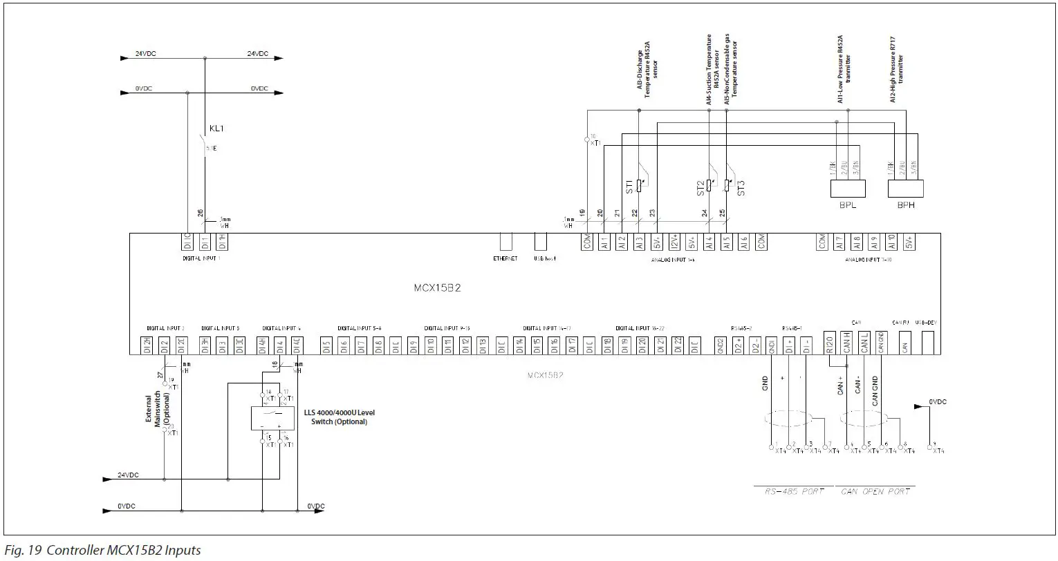
| AI | ANALOG INPUTS | |||||||
| 1 | BPL-1/34 | Low Pressure R452A tranmitter | -1.0 | 34.0 | 0-5 V | Read | 18503 | |
| 2 | BPH-1/59 | High Pressure R717 tranmitter | -1.0 | 59.0 | 0-5 V | Read | 18504 | |
| 3 | Dis. Temp | Discharge Temperature R452A sensor | -30.0 | 170.0 | PT1000 | Read | 18502 | |
| 4 | Suction Temp | Suction Temperature R452A sensor | -50.0 | 170.0 | PT1000 | Read | 18506 | |
| 5 | NC Temp | NonCondensable gas Temperature sensor | -50.0 | 170.0 | PT1000 | Read | 18505 | |
| 6 | ||||||||
| 7 | ||||||||
| 8 | ||||||||
| 9 | ||||||||
| 10 | ||||||||
| 11 | ||||||||
| 12 | ||||||||
| 13 | ||||||||
| 14 | ||||||||
| 15 | ||||||||
| 16 | ||||||||
| 17 | ||||||||
| 18 | ||||||||
| Parameter Name | Description | Min. | Max. | Value/ Type | Unit | RW | ADU | |
| DI | DIGITAL INPUTS | |||||||
| 1 | Status KL1 | Status KL1 – Compressor in operation | 0 | 1 | N.O. | Read | 17504 | |
| 2 | On/Off | On/Off – External Mainswitch | 0 | 1 | N.O. | Read | 17502 | |
| 3 | General Alarm | General Alarm – SW prepared | 0 | 1 | N.O. | Read | 17503 | |
| 4 | LiquidAlarm | Liquid Alarm – from LLS 4000/4000U | 0 | 1 | N.O. | Read | 17505 | |
| 5 | Switch | Switch – Switch to the next purge point (pulse). SW prepared | 0 | 1 | N.O. | Read | 17506 | |
| 6 | Bubbler On | Bubbler On – Force Bubbler solenoid ON. SW prepared | 0 | 1 | N.O. | Read | 17507 | |
| 7 | ||||||||
| 8 | ||||||||
| 9 | ||||||||
| 10 | ||||||||
| 11 | ||||||||
| 12 | ||||||||
| 13 | ||||||||
| 14 | ||||||||
| 15 | ||||||||
| 16 | ||||||||
| 17 | ||||||||
| 18 | ||||||||
| 19 | ||||||||
| 20 | ||||||||
| 21 | ||||||||
| 22 | ||||||||
| 23 | ||||||||
| 24 | ||||||||
| 25 | ||||||||
| 26 | ||||||||
| AO | ANALOG OUTPUTS | |||||||
| 1 | ||||||||
| 2 | ||||||||
| 3 | ||||||||
| 4 | ||||||||
| 5 | ||||||||
| 6 | ||||||||
| 7 | ||||||||
| 8 | ||||||||
| 9 | ||||||||
| 10 | ||||||||
| DO | DIGITAL OUTPUTS | |||||||
| 1 | Compressor | Compressor | 0 | 1 | N.O. | Read | 18007 | |
| 2 | Valve | Valve – Main purge valve AKVA | 0 | 1 | N.O. | Read | 18008 | |
| 3 | Green | Green – Lamp in front panel – Standby | 0 | 1 | N.O. | Read | 18004 | |
| 4 | Yellow | Yellow- Lamp in front panel – Run | 0 | 1 | N.O. | Read | 18005 | |
| 5 | DO_Red | Red – Lamp in front panel – Error | 0 | 1 | N.O. | Read | 18006 | |
| 6 | ICFD_Valve | ICFD_Valve | 0 | 1 | N.O. | Read | 18017 | |
| 7 | Valve1 | Purge valve no. 1 | 0 | 1 | N.O. | Read | 18009 | |
| 8 | Valve2 | Purge valve no. 2 | 0 | 1 | N.O. | Read | 18010 | |
| 9 | Valve3 | Purge valve no. 3 | 0 | 1 | N.O. | Read | 18011 | |
| 10 | Valve4 | Purge valve no. 4 | 0 | 1 | N.O. | Read | 18012 | |
| 11 | Valve5 | Purge valve no. 5 | 0 | 1 | N.O. | Read | 18013 | |
| 12 | Valve6 | Purge valve no. 6 | 0 | 1 | N.O. | Read | 18014 | |
| 13 | Valve7 | Purge valve no. 7 | 0 | 1 | N.O. | Read | 18015 | |
| 14 | Valve8 | Purge valve no. 8 | 0 | 1 | N.O. | Read | 18016 | |
| 15 | Bubler | Water valve for bubler | 0 | 1 | N.O. | Read | 18018 | |
| 16 | Valve9 | Purge valve no. 9 | 0 | 1 | N.O. | Read | 18019 | |
| 17 | Valve10 | Purge valve no. 10 | 0 | 1 | N.O. | Read | 18020 | |
| 18 | Valve11 | Purge valve no. 11 | 0 | 1 | N.O. | Read | 18021 | |
| 19 | Valve12 | Purge valve no. 12 | 0 | 1 | N.O. | Read | 18022 | |
| 20 | Valve13 | Purge valve no. 13 | 0 | 1 | N.O. | Read | 18023 | |
| 21 | Valve14 | Purge valve no. 14 | 0 | 1 | N.O. | Read | 18024 | |
| 22 | Valve15 | Purge valve no. 15 | 0 | 1 | N.O. | Read | 18025 | |
| 23 | Alarm | Alarm | 0 | 1 | N.O. | Read | 18002 | |
Occurring active alarms, possible reasons and recommended action
| Label | Parameter Name | Description | Possible Reason | Recommended action |
| ALARMS | ||||
| A01 | General alarm | Input from AI3 Leads to shut down of IPS 8 | Fault in system connected to the DIO4 | Input from AI3 Leads to shut down of IPS 9 |
| E01 | Temp Sensor Fault | Indicates no signal from temperature sensor (R452a) | Broken wire to R452a temperature sensor | Repair temperature sensor wire or replace temperature sensor |
| E01 | Temp Sensor Fault | Indicates no signal from temperature sensor (R452a) | Electrical supply failure supplying R452a temperature sensor | Repair or replace power source |
| E01 | Temp Sensor Fault | Indicates no signal from temperature sensor (R452a) | Temperature measurement of the R452a line is out of range | Compare temperature with another temperature sensor reading and replace temperature sensor if needed |
| E02 | BPL Sensor Fault | Indicates no signal from pressure transmitter (R452a) | Broken wire to R452A pressure transmitter | Repair pressure transmitter wire or replace pressure transmitter |
| E02 | BPL Sensor Fault | Indicates no signal from pressure transmitter (R452a) | Electrical supply failure to the R422a pressure transmitter | Repair or replace power source |
| E02 | BPL Sensor Fault | Indicates no signal from pressure transmitter (R452a) | Pressure measurement of the R452a line is out of range | Compare pressure with another pressure reading and replace pressure transmitter if needed |
| E03 | BPH Sensor Fault | Indicates no signal from pressure transmitter (R717) | Broken wire to R717 pressure transmitter | Repair pressure transmitter wire or replace pressure transmitter |
| E03 | BPH Sensor Fault | Indicates no signal from pressure transmitter (R717) | Electrical supply failure to the R717 pressure transmitter | Repair or replace power source |
| E03 | BPH Sensor Fault | Indicates no signal from pressure transmitter (R717) | Pressure measurement of the R717 line is out of range | Compare pressure with another pressure reading and replace pressure transmitter if needed |
| E04 | Low temperature | Indicates too low ambient temperature (<-10 °C) | Too low ambient temperature | Move the IPS to a higher ambient temperature |
| E05 | High temperature | Indicates too high ambient temperature (>120 °C) | Too high ambient temperature | Move the IPS to a lower ambient temperature |
| E05 | High temperature | Low R452a charge because of possible leak | Locate and repair leak | Move the IPS to a lower ambient temperature |
| E06 | Low pressure BPL | Indicates too low R452a pressure | Choked restrictor / wrong piping | Factory setting 0.3 bar, we can have several problems: a) Restrictor is blocked (clean it). b) Wrong piping and as addition ammonia is draining, so check piping’s. c) Check SV float |
| E07 | High pressure BPL | Indicates too high R452a pressure | R452s system pressure too high | a) Expansion valve is not working b) To high ambient temperature (24 bar /54 ºC) |
| E08 | Low pressure BPH | Indicates too low R717 pressure | Closed stop valve | Purge points are blocked, or flange is blocked with rubber plug |
| E09 | High pressure BPH | Indicates too high R717 pressure | R717 system pressure too high | Pressure is 24 bar |
| E10 | System is OFF | Indicates status of the main switch | Main switch is OFF | Switch ON the main switch |
| E11 | Memory is full | A memory reset is required | Memory is full from long time operation | Clean MCX memory by means of finding Parameters_UnitConfig_ |
| E12 | Totla purge time error | This occurs when PLT is activated System will automatically restart when CST has expired | Restrictor is blocked | Replace the restrictor |
| E13 | Compressor ERROR | Indicates no status is being received from relay KL01 | Possible broken wire from the MCX | Repair broken wire from the MCX |
| E14 | Liquid alarm | Signal from the LLS that there is liquid in the evaporator | Check piping | |
| E15 | Memory wrong! | Wrong counter values | Carry out: Reset to factory setting | |
| E16 | Discharge sensor error | Indicates no signal from temperature sensor | Check sensor | |
| E17 | Suction sensor error | Indicates no signal from temperature sensor | Check sensor | |
- All alarms except (*) activates red light on box outside
- For alarms not resettable and/or cause not identified, please contact Danfoss
- Level legend: 0 = Read view, 2 = Installer view (code 200) 3 = Danfoss Service view (Contact Danfoss)
Good Practice
- The wiring of Modbus RTU (RS485) must be carried out in accordance with the standard ANSI/TIA/EIA-485-A-1998.
- Galvanic separation shall be provided for segments crossing buildings.
- The common ground shall be used for all devices on the same network inclusive router, gateways etc.
- All bus connections in the cables are made with twisted pair wires.
- The recommended cable type for this is AWG 22/0.32 mm2. If used for longer distances please use a AWG 20/0.5mm2 or AWG 18/0.75mm2 cable. The cables characteristic impedance shall be between 100 – 130Ω The capacitance between conductors shall be less than 100 pf per meter.
Note: the length of the cables influences the communication speed used. Longer cable lengths mean lower baud rate should be used. Maximum cable length allowed is 1200m. Use a minimum 20 cm distance between 110V/230V/400V power line cables and bus cables.
Maintenance/Service/Disposal
Table 03 Maintenance checklist – Perform once a year minimum
| 1 | Use P&I dagram and check that all powered components are working properly |
| 2 | Check for alarms in the MCX controller |
| 3 | Fans, air filters and fins must be cleaned for dirt and dust |
| 4 | Expansion valve must be inspected and must be replaced if damaged |
| 5 | Ensure expansion valves sensor bulb has good contact with suction line |
| 6 | Replace water in water bubble bath. Check pH level frequently and replace when pH > 12.6 |
| 7 | Check cover is mounted correctly and all bolts are tightened accordingly |
| 8 | Check and verify the amperage of the unit |
| 9 | Check for abnormal compressor noises in normal operating conditions (may indicate loose bolts, worn bearings or pistons) |
Table 04 Procedure to isolate IPS for servicing
| Multipoint | Single point purging from receiver | |
| 1 | Close all supply lines from the purge points of the ammonia system. Do not close any stop valve between IPS 8 and float valve | Restart the controller to force pump-down |
| 2 | Restart the controller to force pump-down | Wait 20 minutes |
| 3 | Wait 20 minutes | |
| 4 | Stop the compressor by turning the compressor switch QM1 to the off position | Stop the compressor by turning the compressor switch QM1 to the off position |
| 5 | Close the SVA shut-off valve in the drain line (located under the IPS 8) | Close the SVA shut-off valve in the drain line (located under the IPS 8) |
| 6 | Release the remaining system pressure to atmosphere by opening the SNV drain valve. This can also be done by attaching a permanent magnet on the AKVA 10 valve for forced opening | Release the remaining system pressure to atmosphere by opening the SNV drain valve. This can also be done by attaching a permanent magnet on the AKVA 10 valve for forced opening |
Disposal of the IPS 8
If an IPS 8 unit is worn out and has to be replaced, the disposal must be done in accordance with national legislation and only done by competent personnel.
Danfoss A/S
- Climate Solutions
- danfoss.com
- +45 7488 2222
Any information, including, but not limited to information on the selection of product, its application or use, product design, weight, dimensions, capacity or any other technical data in product manuals, catalogues descriptions, advertisements, etc. and whether made available in writing, orally, electronically, online or via download, shall be considered informative and is only binding if and to the extent, explicit reference is made in a quotation or order confirmation. Danfoss cannot accept any responsibility for possible errors in catalogues, brochures, videos and other material. Danfoss reserves the right to alter its products without notice. This also applies to products ordered but not delivered provided that such alterations can be made without changes to form, fit or function of the product. All trademarks in this material are property of Danfoss A/S or Danfoss group companies. Danfoss and the Danfoss logo are trademarks of Danfoss A/S. All rights reserved.


