access-is VAL100 Barcode NFC RFID Ticket Validator Installation Guide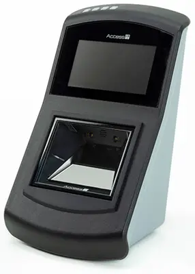
Overview
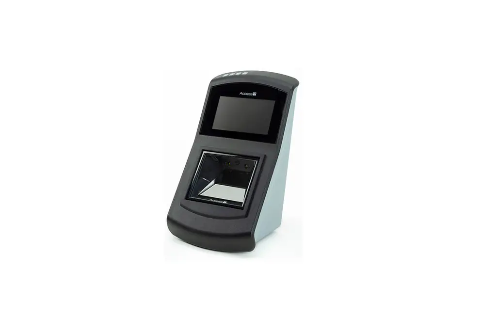
The VAL100 is a ticket validator designed for use on-board buses, trams, trains and boats.
Designed for use in a variety of public transportation automatic fare collection systems, the VAL100 combines a multimedia ticket reader with an open architecture Linux computer to create a mobile ticket validation solution when combined with third-party software.
The validator combines barcode and Near Field Communication (NFC) /Radio Frequency Identification (RFID) reading functionality to provide a single point of presentation for tickets and travel passes – whether presented on a card, mobile phone or tablet.
The VAL100 can be connected over the internet via wired Ethernet, Wi-Fi or cellular modem.
Figure 1: VAL100 on-board validator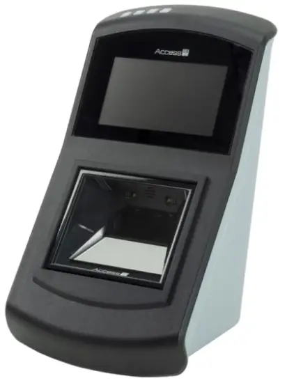
- Robust design for long-term front-line use.
- Single point of presentation barcode/NFC/RFID reader.
- Four Secure Access Module (SAM) card slots (optional).
- Large, clear 480 x 272 TFT LCD colour screen, with illumination that is adjustable in software.
- Four coloured LEDs and a programmable speaker to confirm ticket reads.
- Unique, optimised focal distance improves card and mobile device reading performance.
- Linux computer with a variety of peripheral hardware allowing for integration of ticket validation software.
- Comes with a pole mount kit for ease of installation. This has a quick release mechanism allowing rapid exchange of the VAL100 for ease of maintenance.
- Can be connected to 12–24 V feed from the vehicle’s ignition system. Operational voltage range 10.5 to 33 V.
- Ambient light sensor adjusting the display brightness to the ambient light conditions.
Installation
Mount the VAL100 on a 1.25 inch or 1.4 inch diameter pole.
The validator requires a 12–24 V feed from the vehicle’s ignition. Operational voltage range 10.5 to 33 V.
Warning: Ensure that the vehicle ignition is switched off during installation and when you connect the VAL100.
Unpack the VAL100
Unpack the VAL100 and ensure that you have the following items:
Table 1: VAL100 parts list
| Quantity | Description |
| 1 | VAL100 |
| 1 | Mounting bracket with security lock |
| 2 | Pole clamps |
| 1 | Connector bracket |
| 1 | Pole cover |
| 2 | Security lock keys |
| 1 | 14-way connector* |
| 4 | Crimps 24-18 AWG |
| 20 | Crimps 28-22 AWG |
| 1 | Ferrite |
| 4 | M3 x 6 Torx countersunk screws |
| 6 | M4 x 10 screws with captive washer |
| 1 | Adhesive drilling template |
Only provided for non-4G models.
Additional items for the 4G version of the product only:
Table 2: Items specific to the 4G version of the VAL100
| Quantity | Description |
| 1 | USB dongle cable* |
| 2 | M3X8 P/HD captive washer |
| 2 | M4 x 8 screws with captive washer |
| 3 | M4 nylon insert nut |
| 1 | USB dongle bracket with thermal transfer pad |
| 1 | USB dongle clamp with foam pad |
Comprises a USB adapter cable pre-wired into a 14-way connector block.
Report any missing items or damage immediately to your Sales Representative.
Tool list
To install the VAL100, you will require the following tools:
- Molex 63819-1000 22-28 AWG Crimp Tool
- Molex 63819-0900 18-24 AWG Crimp Tool
- Molex 11-03-0044 Crimp Extraction Tool
- PZ2 Driver
- T10 Driver
- 6 mm Drill Bit
- 25 mm Hole Saw
- Deburring Tool
Cable requirements
The cables required to install the VAL100 are as follows:
Power cable
2-core 18 AWG, STRANDED
Ethernet cable (optional)
Cat 5e/Cat 6 USTP – 24 or 26 AWG, STRANDED
USB cable (optional)
USB 2.0 compatible cable – no longer than 4.5 metres
Pole mount procedure
Use the supplied pole mount kit to install the VAL100 on a pole in the vehicle. You can mount the VAL100 on a 1.25 inch or 1.4 inch diameter pole.
Before starting this procedure, ensure that you have the correct mounting kit for the pole size that you are using and the required tools and cables.
Refer to the Installation drawings (on page 13) if you need further help with installation procedure.
Warning: Ensure that the vehicle ignition is switched off during installation and when you attach the VAL100 to the mounting bracket. Access-IS recommend that a 3 A fuse is connected in line with the 12/24 V supply cable.
- Wrap the drilling template around the pole.
Use the horizontal lines at the top and bottom of the template to ensure that the template is aligned correctly. - Drill holes into the pole, as marked on the template. Three holes are required on the front face, two holes on the back. A 6 mm drill and 25 mm hole saw are recommended.
- Deburr all holes inside and outside of the pole with a deburring tool.
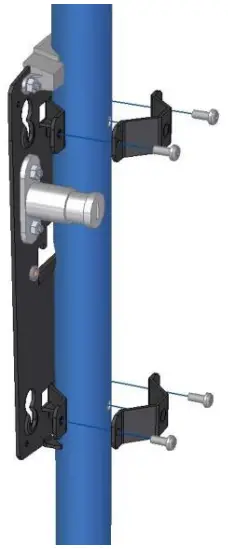
- Position the mounting bracket on the pole ensuring that the locating studs engage in the two smaller holes in the front face of the pole.
4G only: If you are using the 4G dongle, pass the provided USB dongle cable through the cable aperture in the mounting bracket before carrying out this step. Make sure the USB cable passes the pole on the right side (when looking at it from the front of the validator). - Position each pole clamp against the back of the pole and attach to the mounting bracket using two M4 screws.
- Thread the cables through the pole.
The cables must exit the pole through the 25 mm hole and provide sufficient slack for crimping. - Strip and crimp the ends of the cables.
- Insert the crimps into the white connector block. 4G only: The dongle cable comprises a 14-way white connector block, with a USB adapter cable pre-wired into it, leaving 10 available pins to use for Ethernet and power. There is no space for wiring another USB cable for other uses.
Refer to the wiring guide (on page 11) and note the orientation of the white connector block. - 4G only: Position the USB dongle bracket over the three threaded studs on the mounting bracket. Secure with an M4 nylon insert nut.
- 4G only: Secure the socket of the USB dongle cable to the USB dongle bracket using two M4 x 8 screws with captive washer.
- 4G only: Unpack the 4G USB dongle and load a Standard sized SIM card (also known as a Mini SIM). Refer to the dongle’s quick start documentation for correct SIM loading instructions.
- 4G only: Insert the 4G USB dongle into the socket of the USB dongle cable. Ensure that the dongle is inserted as far down as it will go. Fit the USB dongle clamp over the 4G USB dongle lining up the holes with those in the USB dongle bracket. Secure the clamp with two M4 x 8 screws, tightening them fully.
- 4G only: Secure the ferrite of the USB dongle cable to its fixing position on the USB dongle bracket using a ‘zip tie’.
- Add sleeving or tape to the external sheath and clip the ferrite to the power cable, less than 100 mm from the connector.
It is recommended that you to tie the cables together with a ‘zip tie’. - Push the white connector block into the connector bracket and secure the assembly to the mounting bracket using two M4 screws.
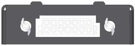
The following drawing shows the orientation of the connector.
Figure 2: Connector block orientation
- Ensure the cables are positioned centrally, to avoid contact with any sharp edges, and carefully feed back any slack wire.
- Fit the rear plastic cover and attach to the mounting bracket using four M3 screws (use a T10 Torx tool to secure the screws).
You can now fit the blanking plate or validator to the mounting bracket. - Locate the fixings on the back of the blanking plate or validator in the holes on the blanking plate and slide down until fully engaged.
- To secure the equipment, push in the security lock until it clicks.
SAM card installation
SAM cards are usually installed at the factory. For on-site installation, follow these steps.
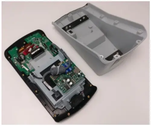
- Remove the 11 screws securing the rear cover housing and prise the front and rear cover housing apart.

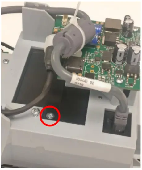
- Remove the screw securing the cover plate.

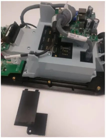
- Remove the SAM cover plate.

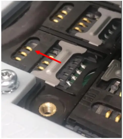
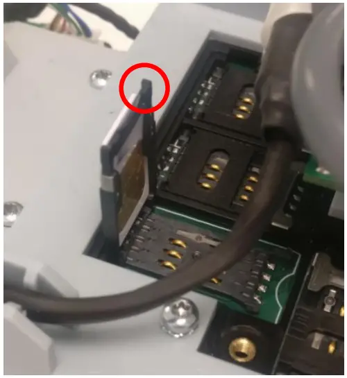
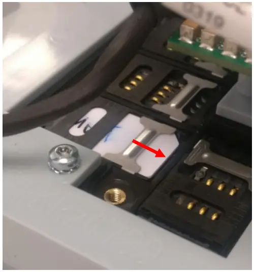
- Slide the metal lock bar to release the SAM socket cover.

- Pivot the SAM socket cover up and insert the card (note the orientation of the chamfered corner on the card).

- Pivot the cover closed and slide the lock bar to the lock position.

- Replace the SAM cover plate and replace the screw.
- Re-fit the main rear cover housing and secure with 11 screws.
- Test the device.
Test the device
Once you have connected the VAL100 to the mounting plate, you can test the validator. Refer to the User Guide provided by the System Integrator for instructions on how to test the validator. If the device fails to respond when connected, refer to the Troubleshooting section in this document.
Troubleshooting
If the VAL100 does not appear to be working, refer to the following table to help identify and resolve the problem. For further assistance, contact Customer Support ([email protected]).
Alternatively, use the Contact Customer Support page on the Access-IS website.
Note: Do not attempt to disassemble the VAL100 if it does not operate correctly. Any attempt to do so may be dangerous and will invalidate the warranty.
Table 3: Troubleshoot the VAL100
| Problem | Solution |
| VAL100 not transmitting data to host | Check that all cable connections between the VAL100 and host are secure and are correctly wired. Ensure that the unit has power. |
| VAL100 cannot scan ticketing media | Ensure that the unit is configured to read the media that you are scanning. If scanning a document, ensure that the print quality is good. If scanning a barcode on a mobile phone, ensure that you set the screen backlight on the phone to its brightest setting. |
Maintenance
Cleaning
Clean the glass with a lint-free cloth. If the glass is dirty, wipe the glass with a lint-free cloth moistened with isopropyl alcohol or use an alcohol wipe. Do not use abrasive cleaners.
Storage
Store the unit in its original box, at a temperature of -30°C to 70°C.
Wiring guide
Figure 3: Wiring guide and connector orientation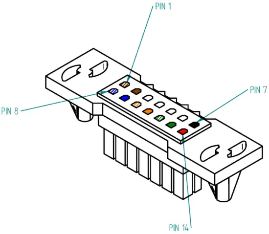
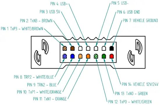
Table 4: Molex, Ethernet, USB and Power connections
| Molex | Ethernet | USB* | Power |
| 1 | 7 – TxP3 – WHITE/BROWN | ||
| 2 | 8 – TxN3 – BROWN | ||
| 3 | USB 5 V | ||
| 4 | USB+ | ||
| 5 | USB- | ||
| 6 | USB GND | ||
| 7 | BLACK – VEHICLE GROUND | ||
| 8 | 5 – TRP2 – WHITE/BLUE | ||
| 9 | 4 – TRN2 – BLUE | ||
| 10 | 1 – TxP1 – WHITE/ORANGE | ||
| 11 | 2 – TxN1 – ORANGE | ||
| 12 | 3 – TxP0 – WHITE/GREEN | ||
| 13 | 6 – TxN0 – GREEN | ||
| 14 | RED – VEHICLE 12/24 V |
Pre-wired with a USB adapter cable in the 4G version of the product.
Installation drawings
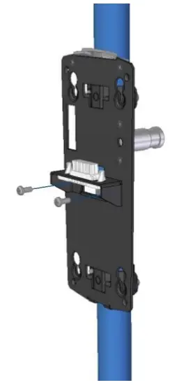
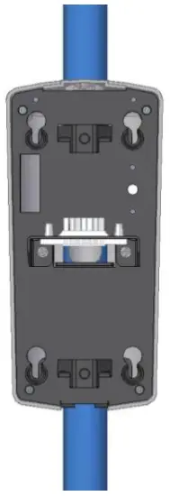
- Figure 4: Attach the mounting bracket to the pole

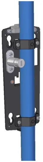
- Figure 5: Mounting bracket attached to the pole

- 4G only
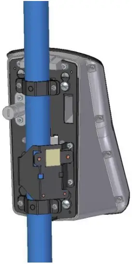
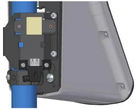
Figure 6: Fit the USB dongle bracket onto the mounting bracket and secure 4G only
- 4G only
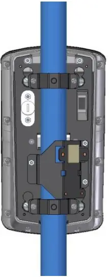
Figure 7: USB dongle bracket showing all fixings
- 4G only
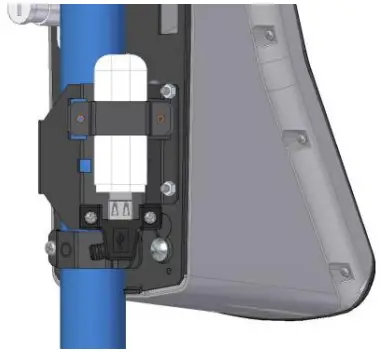
Figure 8: Secure the USB socket on the USB dongle cable to the USB dongle bracket
- 4G only
Figure 9: Insert the 4G dongle and secure with the 4G dongle clamp
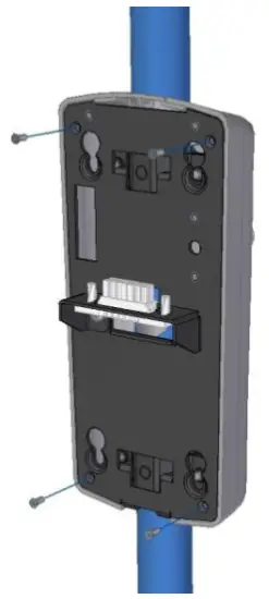
- Figure 10: Connect the wiring block

- Figure 11: Attach the back cover
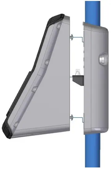
- Figure 12: Positions of the keyholes for attaching the validator

- Figure 13: Attach the validator

Specifications
| Specification | Details |
| Dimensions – Main unit | 145.5 mm x 265 mm x 188 mm (W x H x D) |
| Weight | Validator: 1.7 kg, Mounting kit: 0.95 kg |
| Environmental | Operating temperature: -20ºC to 50ºC Storage temperature: -30ºC to 70ºC Humidity: 0–95% RH, non-condensing |
| Body | PC/ABS |
| Display | 480 x 272, widescreen, sunlight-readable |
| Glass | 4 mm Toughened White Soda Lime; BS EN60068-2-75 & IEC 62262:2002, rated to 3.5J impact |
| Power requirements | 10.5–33 volts – automotive grade power supply |
| Communications and host | Communication: 3G*/4G*/GPRS* (*Optional) Connection: USB, Ethernet, GPS; Wi-Fi; Bluetooth 4/Bluetooth Low Energy; RS232 Host: Dual core 1GHz 1GB RAM, 32GB memory with 128GB optional upgrade, Linux OS, full API and device access for developers LED indicators: 4 x RGB LEDs Sound: Speaker with digital control for audio playback |
| Reader – Barcodes | Reads the following barcode symbologies: Linear: EAN, UPC, Code 2 of 5, Interleaved 2 of 5, IATA 2 of 5, Code 39, Code 128 2D: IATA resolution 792, PDF417, Aztec, DataMatrix and QR codes Performance: Will read 2D barcodes from paper, mobile phones and tablets |
| Reader – NFC/RFID | Reads NFC-enabled mobile phones and contactless smart and banking cards EMV Level 1 and Level 2. PCI-SRED 5.1 compliant, 4 SAM slots NFC tags supported: Mifare 1K/4K Classic tags, Mifare UL, Mifare Plus, ISO14443-4 Type A, ISO14443-4 Type B, HID iClass tags (only CSN read supported), NXP iCode tags, Apple pay/VAS Payment Schemes supported: VISA, MasterCard, Discover, American Express |
| MTBF | 50,000 hours |
| Approvals | EMC
Radio
|
Main model numbers
Validators
| Model | Barcode | RFID NFC | cEMV | Wi-Fi | Bluetooth BLE | USB | Serial | Ethernet | Flash memory |
| VAL100-210-WE-D3 | 32GB | ||||||||
| VAL100-210-WE-D1 | 128GB | ||||||||
| VAL100-210-WS-D3 | 32GB | ||||||||
| VAL100-210-WS-D1 | 128GB | ||||||||
| VAL100-210-WB-D3 | 32GB | ||||||||
| VAL100-210-WB-D1 | 128GB | ||||||||
| VAL100-220-WE-D3 | 32GB | ||||||||
| VAL100-220-WE-D1 | 128GB | ||||||||
| VAL100-220-WS-D3 | 32GB | ||||||||
| VAL100-220-WS-D1 | 128GB | ||||||||
| VAL100-220-WB-D3 | 32GB | ||||||||
| VAL100-220-WB-D1 | 128GB |
Mounting kits
| Model | Cellular modem prepared | Diameter (inches) | Diameter (mm) |
| VAL100-00-MA | 1.25 | 31.75 | |
| VAL100-00-MC | 1.4 | 35.5 | |
| VAL100-00-PK4G-125 | 1.25 | 31.75 | |
| VAL100-00-PK4G-140 | 1.4 | 35.5 |
Document history
| Version | Date | Description |
| 1.0 | 15/09/2016 | First issue. |
| 1.1 | 06/10/2016 | Changes to USB connections and wiring guide. |
| 2.0 | 10/01/2017 | Addition of 4G dongle installation steps. |
| 3.0 | 10/12/2020 | Changed compliance statements and overview text, removed 1.5 inch pole option, changed operational voltage range, added SAM card installation, updated specifications and approvals, revised main model number section. |
Warnings
This manual contains important information regarding the installation and operation of the VAL100. For safe and reliable operation of the imager, installers must ensure that they are familiar with, and fully understand, all instructions contained herein.
Warranty
Access Ltd warrants that this product shall be free from defects in workmanship and materials for a period of one year from the date of original purchase. If the product should fail to operate correctly in normal use during the warranty period, Access will replace or repair it free of charge. No liability can be accepted for damage due to misuse or circumstances outside Access’ control. Access will not be responsible for any loss, damage or injury arising directly or indirectly from the use of this product. Access’ total liability under the terms of this warranty shall in all circumstances be limited to the replacement value of this product.
(Non- RFID version)
This product meets the requirements of the following directives and carries the CE marking accordingly; 2014/35/EU Low Voltage Directive, 2014/30/EU EMC Directive, 2015/863/EU RoHS 3 Directive.
(RFID version)
This product meets the requirements of the following directives and carries the CE marking accordingly; 2014/53/EU Radio Equipment Directive, 2015/863/EU RoHS 3 Directive.
Compliance Statement (United States)
Supplier’s Declaration of Conformity
47 CFR §2.1077 Compliance Information
Unique Identifier: VAL100 On-board Validator Barcode/NFC & RFID/cEMV Payments
Responsible Party – US contact information:
MONICA GLOZER
ACCESS-IS
ROEDL LANGFORD DE KOCK, LLP
110 SOUTH TOWER
225 PEACHTREE ST. NE
ATLANTA
GA 30303
Email: [email protected]
FCC Compliance Statement (Products subject to Part 15):
This device complies with part 15 of the FCC Rules. Operation is subject to the following two conditions: (1) This device may not cause harmful interference, and (2) this device must accept any interference received, including interference that may cause undesired operation.
NOTE: This equipment has been tested and found to comply with the limits for a Class B digital device, pursuant to part 15 of the FCC Rules. These limits are designed to provide reasonable protection against harmful interference in a residential installation. This equipment generates, uses and can radiate radio frequency energy and, if not installed and used in accordance with the instructions, may cause harmful interference to radio communications. However, there is no guarantee that interference will not occur in a particular installation. If this equipment does cause harmful interference to radio or television reception, which can be determined by turning the equipment off and on, the user is encouraged to try to correct the interference by one or more of the following measures:
- Reorient or relocate the receiving antenna.
- Increase the separation between the equipment and receiver.
- Connect the equipment into an outlet on a circuit different from that to which the receiver is connected.
- Consult the dealer or an experienced radio/TV technician for help.
The RFID version contains FCC approved Access-IS Module FCC ID: ZERCPM01
Canadian Department of Communications RFI statement
This equipment does not exceed the class A limits for radio noise emissions from digital apparatus set out in the radio interference regulations of the Canadian Department of Communications.
The RFID version contains approved module IC: 9653A-CPM01.


