![]() Veue Wire Guide
Veue Wire Guide
Instruction Manual VEUE | WIRE GUIDE
INSTALLATION MANUAL
SECTION A | TOOLS AND ADDITIONAL ITEMS REQUIRED
PART A – TOOLS REQUIRED
- Saw
- Drill
- Screw Driver – Philips Head & Flat Head
- Jaw Pliers
- Allen Key Set
- Mallet
- Scissors
- Measuring Tape
- Pencil
PART B – ADDITIONAL ITEMS REQUIRED (NOT SUPPLIED)
To assemble an Veue | Wire Guide, the following non-stocked items are required:
- Fixings for Box/Open Brackets/Hardware (ensure appropriate fixings are used to suit application)
- Trims to conceal packing (if required)
PART C – BLIND ITEMS REQUIRED 
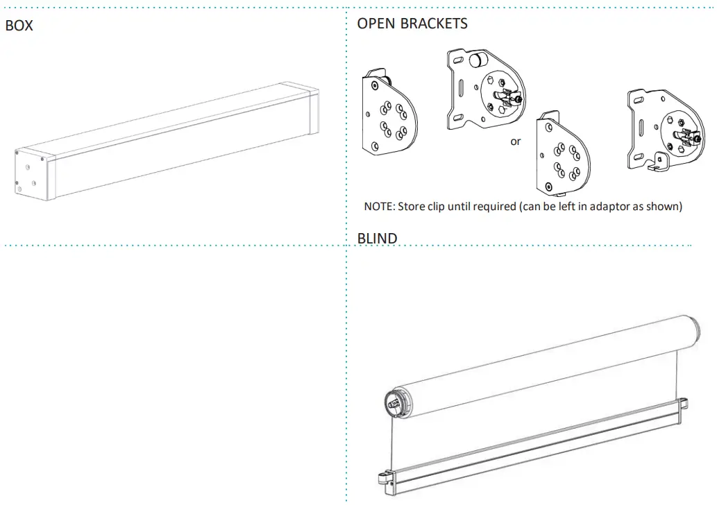
PART D – BLIND ITEMS REQUIRED
WIRE GUIDE AND FIXING HARDWARE
OPTION 1 – Hook Terminal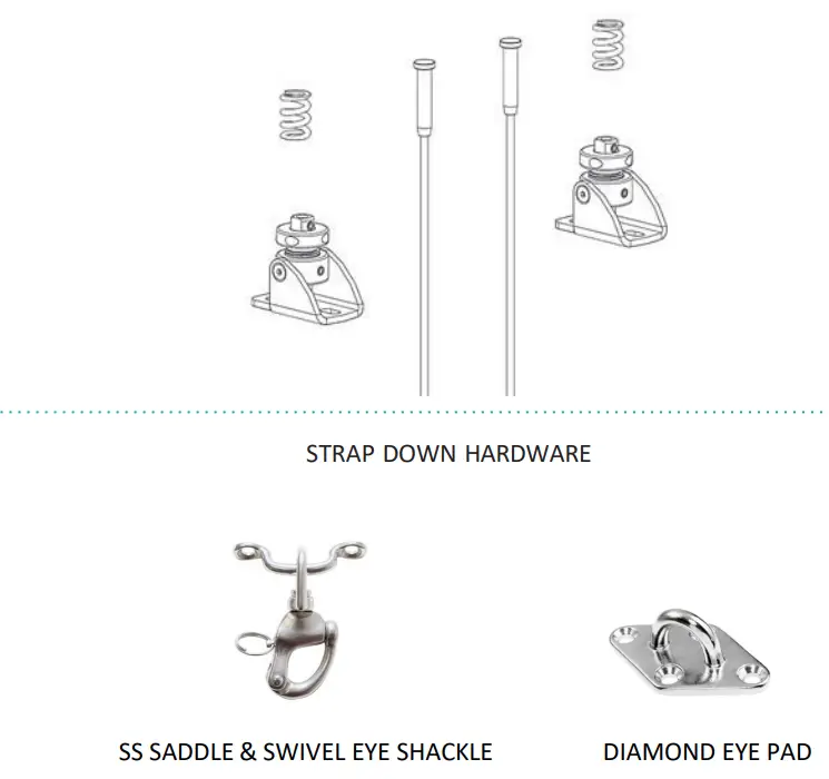
PART A – PREPARING INSTALLATION
STEP 1. – CHECK FOR OBSTRUCTIONS
Check for any obstructions that may interfere in installation.
STEP 2. – CHECK VERTICAL & HORIZONTAL INSTALLATION DIMENSIONS
VERTICAL DIMENSIONS 
Check if top of installation space is level.
• If H1 ≠ H2, corrective actions may need to be considered prior to installation
HORIZONTAL DIMENSIONS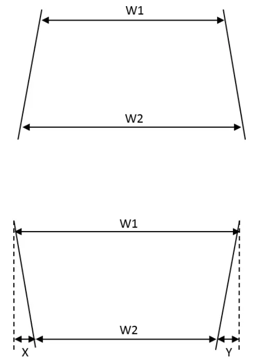
If W2 ≥ W1, W1=Blind Width(proceed to Part B)
If W2 < W1, by a value of: 0-20mm, Proceed to Part B (W1 = Blind Width) 20+, Consider corrective action to square installation space
PART B – BOX INSTALLATION
STEP 1 – INSTALL BOX TO WALL/CEILING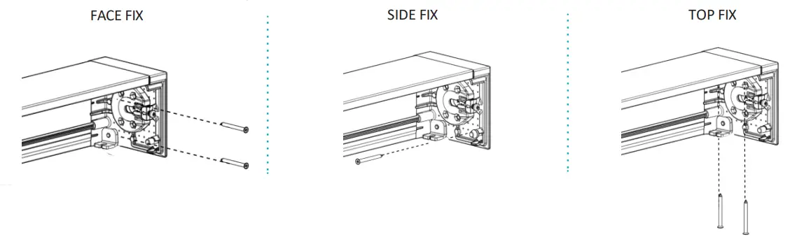
NOTE:
Use appropriate fixings to suit application. Ensure Box is Aligned and Level. Ensure 2 fasteners are used per side.
PART D – OPEN BRACKET INSTALLATION
STEP 1 – INSTALL BRACKETS TO WALL/CEILING 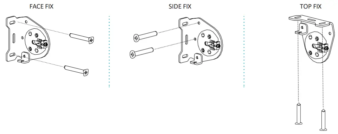
NOTE:
Use appropriate fixings to suit application. Ensure 2 fasteners are used per side. Ensure brackets are aligned and level.
Measure brackets end to end to confirm measurement is correct.
PART D – BLIND INSTALLATION
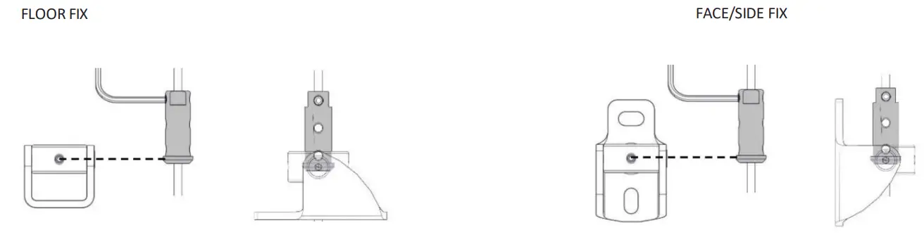
STEP 1 – MARK &SECURE WIRE GUIDE FIXINGS AND TRIM WIRE TO SUIT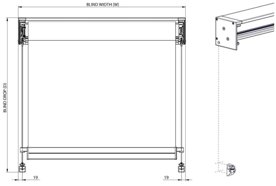
NOTE: Cut wire to assist installation (ensure wire is not cut too short, excess can be trimmed later)
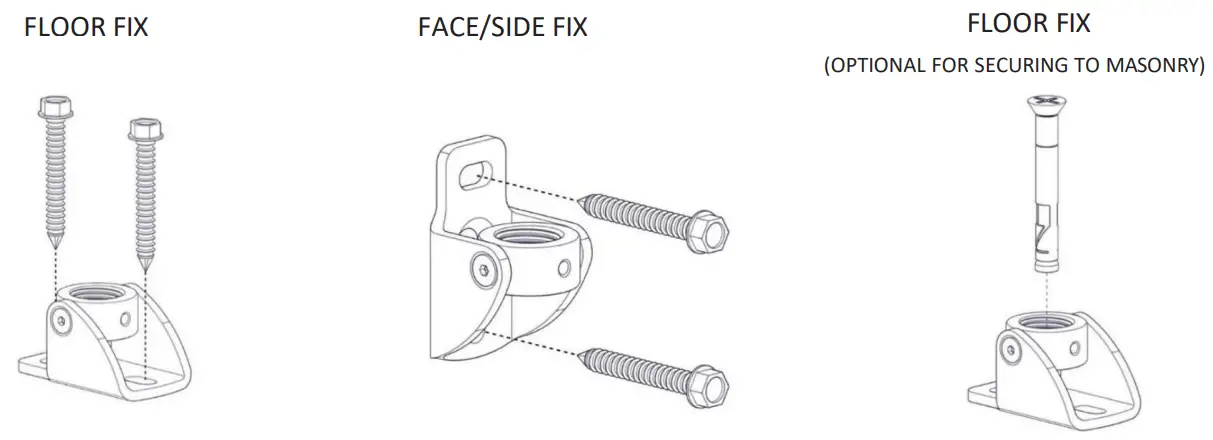 NOTE: Ensure fasteners suit substrate application Max fastener size #10, Max Dynabolt Size: M6
STEP 2 – INSERT SPRING ONTO WIRE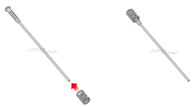
STEP 3 – ATTACH WIRE AND SPRING TO BRACKET
OPTION 1 – HOOK TERMINAL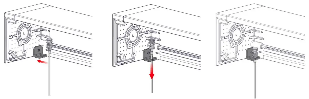
NOTE: Tube hardware not shown for clarity of wire installation
STEP 4 – INSERT BLIND INTO BOX 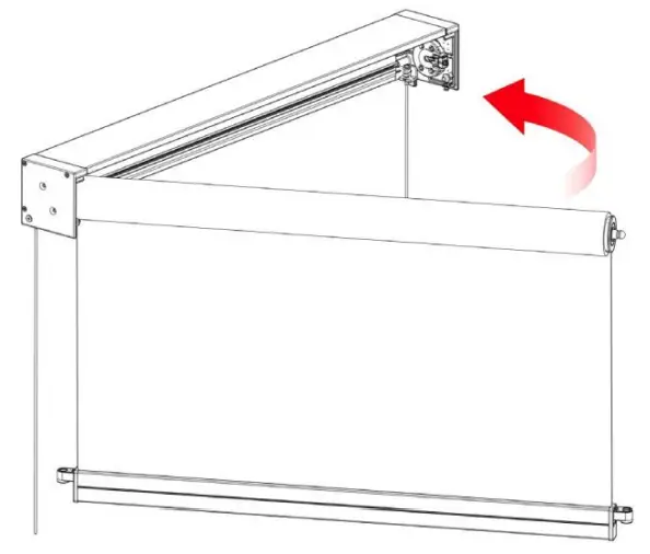
NOTE:
- Insert control end first
- Ensure blind is secure
STEP 5 – INSERT WIRE THROUGH WEIGHT BAR END CAP FLOATS 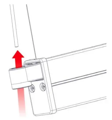
STEP 6 – INSERT CLIP INTO IDLER ADAPTER
IDLER END 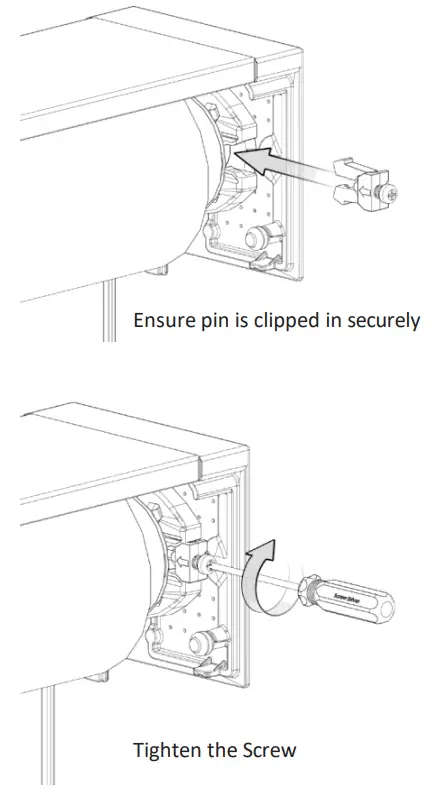
STEP 7 – FEED THROUGH MOTOR CABLE (FOR MOTOR ONLY) 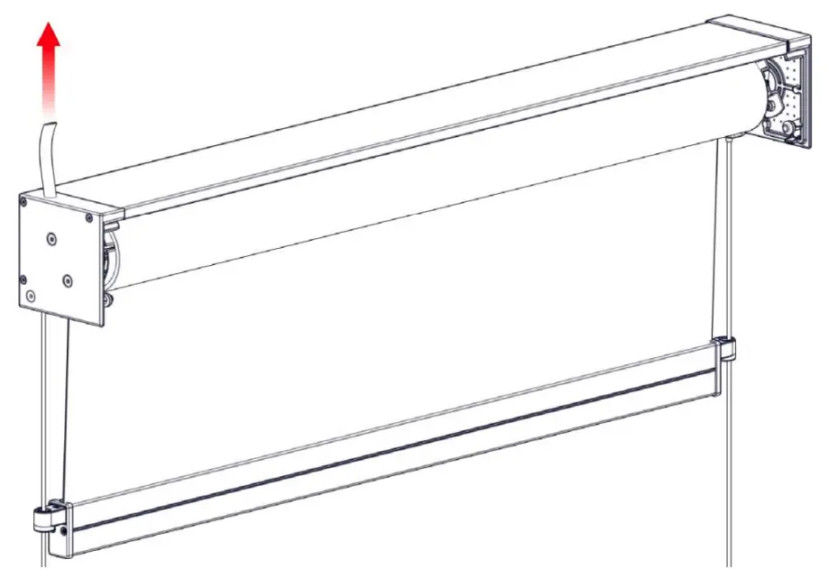
STEP 8 – RUN BLIND DOWN + CENTRE 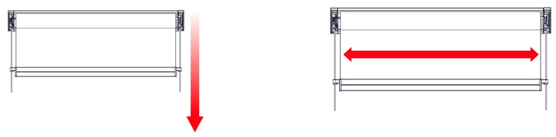
STEP 9 – TEST BLIND OPERATION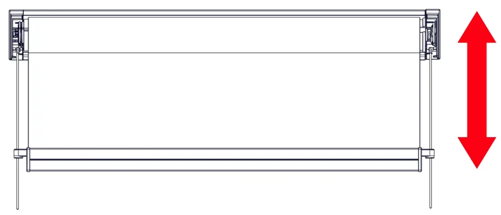
For motor operation, ensure wiring is correct and motor is operating correctly. For gear operation, ensure operation is smooth.
Once blind is operating correctly, proceed to next steps.
PART D – LOCK OFF SS SADDLES & ATTACH DIAMOND EYE PAD
CLIPs – IF ORDERED
STEP 1 – UNLOCK SADDLES AND SLIDE TO REQUIRED POSITION (SUGGESTED 100MM NOMINAL FROM END CAP), LOCK BOTH SADDLES TO THE BOTTOM RAIL
STEP 2 – ATTACH THE DIAMOND EYE PAD DIRECTLY BELOW SWIVEL EYE SHACKEL WITH APPROPRIATE SCREWS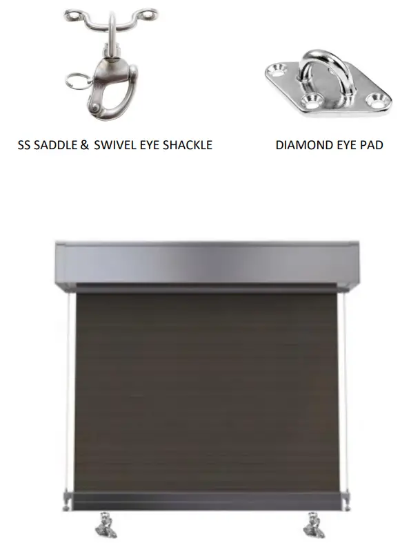
PART E – TENSION GUIDELINES
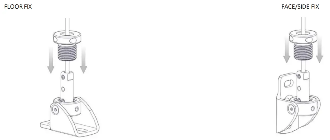
STEP 1 – SLIDE ADJUSTING SLEEVE THEN WIRE TERMINAL ONTO WIRE AND TIGHTEN UP OUT OF THE WAY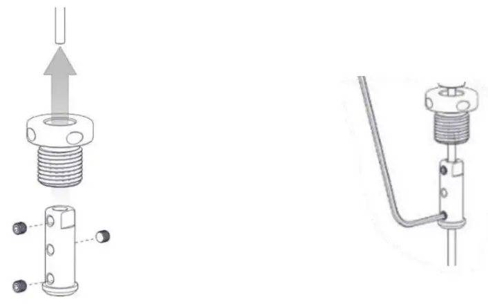
NOTE: Use 2mm Allen Key
STEP 2 – PULL WIRE STRAIGHT AND ALIGN TERMINAL FLANGE WITH M4 GRUB SCREW, CLAMP TO WIRE
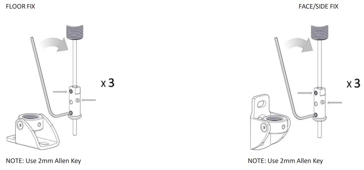
STEP 3 – TIGHTEN REMAINING GRUB SCREWS ON WIRE (TIGHTEN 3X GRUB SCREWS PER WIRE)
STEP 4 – LOWER ADJUSTING SLEEVE INTO COLLAR TO TENSION WIRE
STEP 5 – SCREW IN ADJUSTING SLEEVE UNTIL WIRE BEGINS TO TENSION 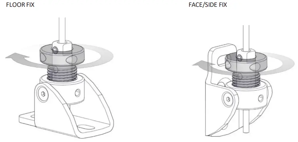
STEP 6 – TO APPLY MIN REQUIRED TENSION, TIGHTEN WITH 5X TURNS USING ALLEN KEY 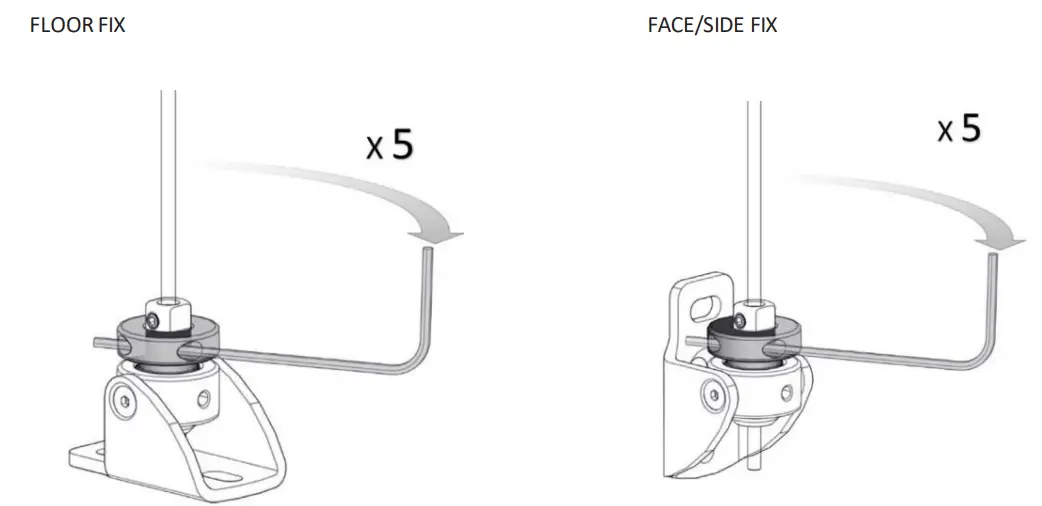
STEP 7 – ONCE TENSIONED, SCREW IN GRUB SCREW TO PREVENT LOSING TENSION 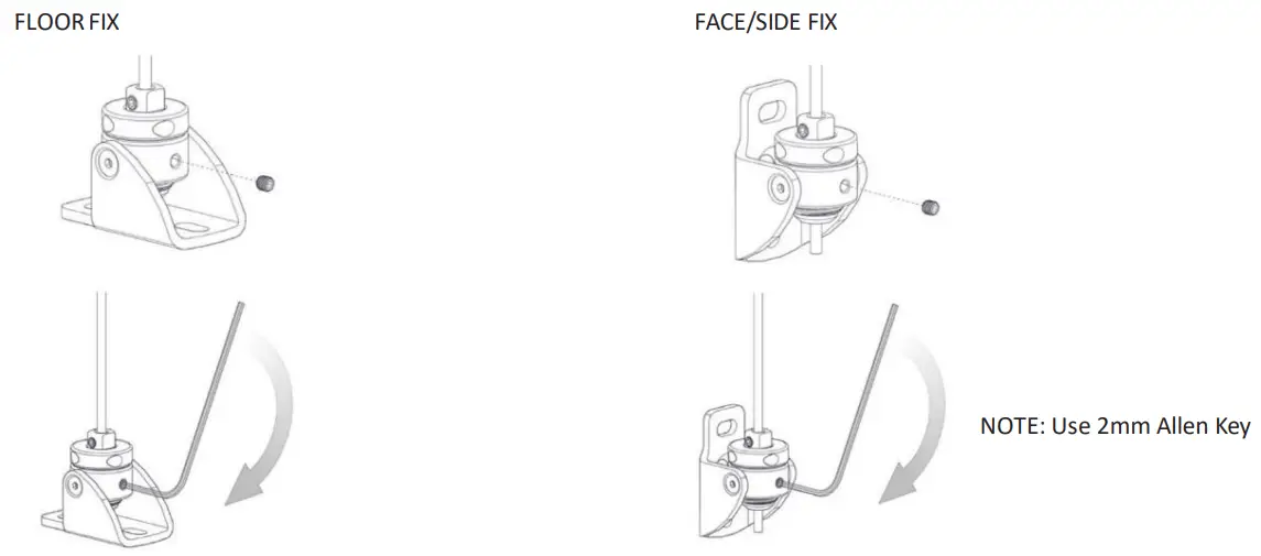
STEP 1 – SWING BOX COVER INTO BOX TOP AND CLIP INTO PLACE 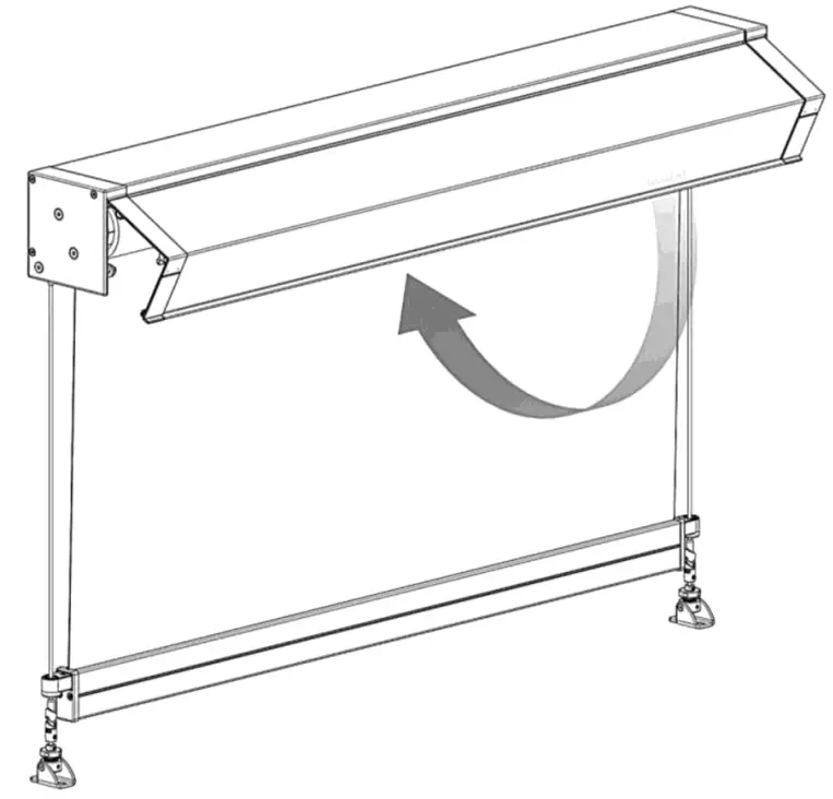
STEP 2 – SECURE COVER AT BOTH ENDS 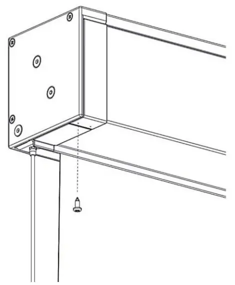
Note: It is recommended that the Box Cover be fixed to ensure it is not accidentally dislodged.
BOX 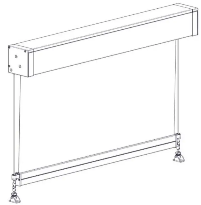
OPEN 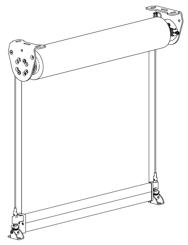
TROUBLESHOOTING
| NO. | PROBLEM | CAUSE | SOWTION |
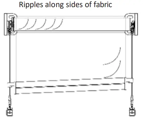
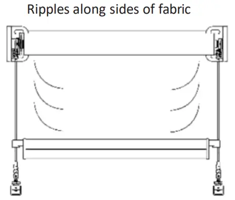 | Blind rolled up loran extended period of time. | This occurrence is inherent to roller systems and is more prevalent In some fabrics. Leave blind down for 1 —4 hours; most ripples should disappear. | |
| Not enough weight in weight bar. | Refer to Product Specs. Add ballast. | ||
| Installation is not square. | Check blind roll is Installed level. | ||
| Fabric permanently damaged due to inadequate handling duringassembly, transportation, installation or use. | Replace fabric and ensure it is handled with care. | ||
| 2 | Blind does not fully open/jams | Position of wire guides at base is incorrect. | Check if wire guide fixing at floor/base are positioned in line with the Top Terminal. If fixing is too far inwards of the terminal then reposition. Refer to Part C, Step 1 of this document for wire guide positioning details. |
| Incorrect motor stop limits used. | Refer to motor instructions to reset stop limits. | ||
 | Blind roll is not level, thus weight bar ap- pears uneven. | Ensure blind is installed level | |
| Blind has been operated in excessivewind conditions. | Check blind roll when the blind is fully raised. If ripples are evident on roll, open blind fully (without the presence of wind) to allow the blind to track down evenly. Raise and lower blind a number of times to check operation. | ||
| Fabric is not installed straight. | Ensure fabric Is assembled straight onto tube and weight bar. | ||
| Locks go out of sync | Locks are not level | Lower blind until fabric is slack then lift one side so that the lock disengages | |
| Uneven Weight Bar (see above) | |||
| Obstruction preventing weight bar lowering through lock | Remove obstruction to allowwetht bar to reach Its low- est point |
![]()


