![]() 24 312 Ceiling Mounted Downlight
24 312 Ceiling Mounted Downlight
Instruction Manual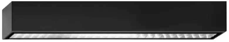 40.22
40.22
Technical amendments reserved
24 312![]()
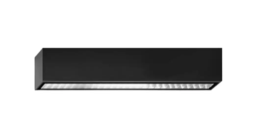
24 312 Ceiling Mounted Downlight
Ceiling mounted downlight 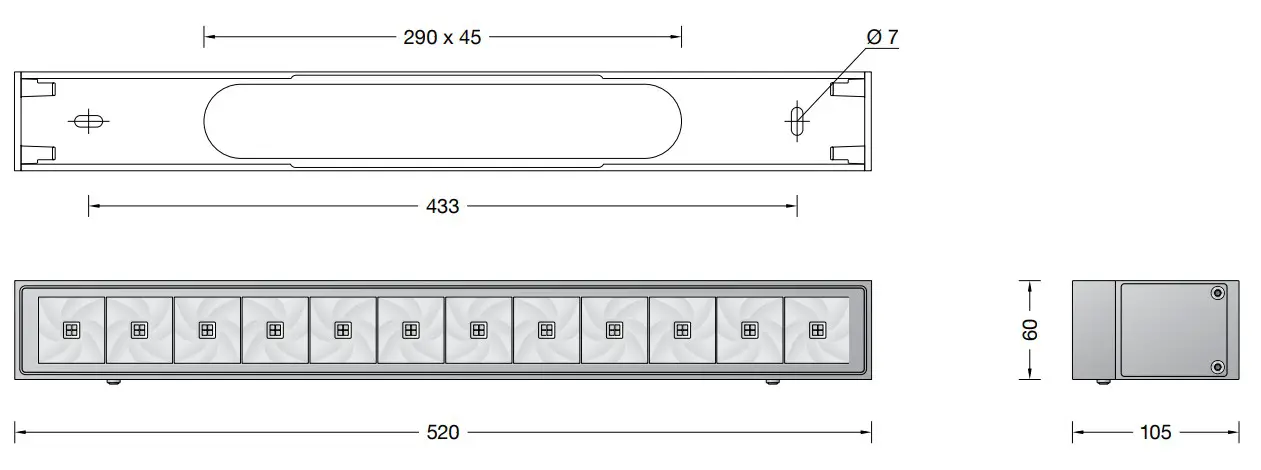 Instructions for use
Application
Ceiling-mounted downlight with symmetrical wide beam light distribution.
Bands of light of different lengths can be created by installing single luminaires in rows.
A luminaire for linear illumination both indoors and out.
Product description
Luminaire made of aluminium alloy, aluminium and stainless steel
BEGA Unidure ® coating technology
Colour graphite
Matt safety glass
Silicone gasket
BEGA Vortex Optics®.
Reflector surface made of pure aluminium
Mounting bar with 2 elongated holes
7 mm width, 433 mm spacing
2 screw cable glands with strain relief for
through-wiring of the mains supply cablefrom ø 7,5–10,8 mm, max. 5 G 1,5@
1 screw cable gland closed at the factory with a dummy plug
Connecting terminal 2.5@ with plug connection
Earth conductor connection
LED power supply unit 220-240 ![]() 0/50-60 Hz
0/50-60 Hz
DC 176-276 V
During DC operation the LED power is reduced to 15 %
DALI-controllable
Number of DALI addresses: 1
Basic insulation is provided between the mains and control cables
BEGA Thermal Control®
Temporary thermal regulation to protect temperature-sensitive components without switching off the luminaire
Safety class I![]() Ballproof according to DIN VDE 0710 part 13
Ballproof according to DIN VDE 0710 part 13
Protection class IP 65
Dust-tight and protection against water jets
Impact strength IK07
Protection against mechanical impacts < 2 joule![]() – Safety mark
– Safety mark![]() – Conformity mark
– Conformity mark
Weight: 2.9 kg
This product contains light sources of energy efficiency class(es) C
Overvoltage protection
The electronic components installed in the luminaire are protected against overvoltage in accordance with DIN EN 61547.
To achieve an additional protection against e. g. transients, etc. we recommend separate overvoltage protection components.
You can find them on our website at www.bega.com.
Safety
The installation and operation of this luminaire are subject to national safety regulations.
Installation and commissioning may only be carried out by a qualified electrician.
The manufacturer accepts no liability for damage caused by improper use or installation.
If subsequent modifications are made to the luminaire, the person responsible for these modifications shall be considered the manufacturer.
Lamp
| Module connected wattage | 15.8 W |
| Luminaire connected wattage | 18.3 W |
| Rated temperature | ta = 25 °C |
| Ambient temperature | ta max = 55 °C |
24 312 K3
| Module designation | LED-0771/830 |
| Colour temperature | 3000 K |
| Colour rendering index | CRI > 80 |
| Module luminous flux | 2950 lm |
| Luminaire luminous flux | 2191 lm |
| Luminaire luminous efficiency | 119,7 lm / W |
24 312 K4
| Module designation | LED-0771/840 |
| Colour temperature | 4000 K |
| Colour rendering index | CRI > 80 |
| Module luminous flux | 3030 lm |
| Luminaire luminous flux | 2261 lm |
| Luminaire luminous efficiency | 123,6 lm / W |
Lighting technology
Half beam angle 55°
Installation
Undo hexagon socket screws (wrench size 3) and lift mounting bar out of luminaire housing.
Lead mains supply cable through the opening of the mounting bar.
Fix mounting bar with enclosed or other suitable fixing material onto mounting surface.
It is absolutely essential to have an even mounting surface. Undo hexagon socket screws and remove connecting compartment cover from the luminaire housing.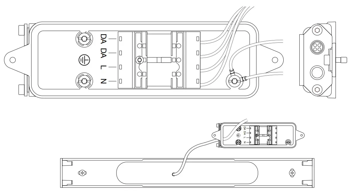 Lead mains supply cable through the cable entry of the connecting compartment cover.
In case of through-wring remove the factory installed dummy plug.
Tighten screw cable gland.
Make earth conductor connection and electrical connection to the connecting terminal (plug connection).
For digital control please use the connecting terminal DA, DA.
In case this terminal is not used the luminaire will be operated at full light output.
In order to guarantee the maximum service life of the electrical components, the enclosed desiccant pouch must be placed in the luminaire.
Remove the desiccant pouch from the foil packaging and place it in the position marked by the red information label immediately before finally closing the luminaire.
Push plug into coupler as far as it will go.
Assemble connecting compartment cover.
Make sure that the gasket is positioned correctly.
Hang the luminaire housing in the mounting rail and screw it in place.
Cleaning · Maintenance
Clean luminaire regularly with solvent-free cleansers from dirt and deposits.
Do not use high pressure cleaners.
Replacing the LED module
The designation of the LED module is noted on a label in the luminaire.
The light colour and light output of BEGA replacement modules correspond to those of the modules originally fitted.
The module can be replaced by qualified persons using standard tools.
Disconnect the system and open the luminaire.
Please follow the installation instructions for the LED module.
Inspect and, if necessary, replace the luminaire gaskets.
Defective glass must be replaced.
Close the luminaire.
Spares
| Housing + Glass graphite | 25 000 027 |
| LED power supply unit | DEV-0158/350i |
| LED module 3000 K | LED-0771/830 |
| LED module 4000 K | LED-0771/840 |
| Reflector | 76 001 591 |
| Gasket connecting compartment cover | 83 001 866 |
| Gasket housing | 83 002 131 |
![]() BEGA Gantenbrink-Leuchten KG
BEGA Gantenbrink-Leuchten KG
Postfach 31 60
58689 Menden
[email protected]
www.bega.com


