![]()
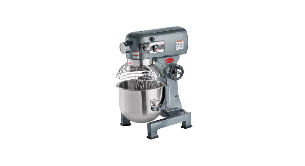
User Manual
![]()
Models: MX20
Shifting gears while this unit is running will void the warranty.
Please read and keep these instructions. Indoor use only.
www.AvantcoEquipment.com
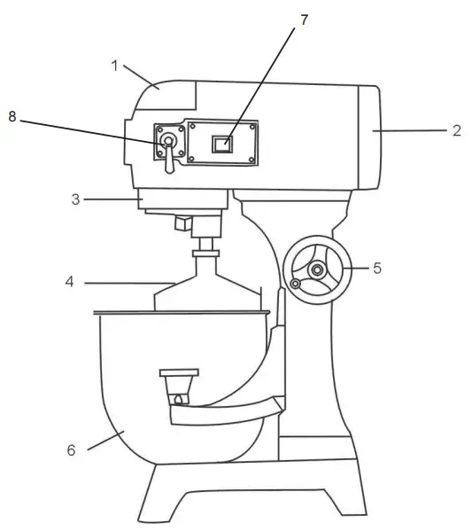
Parts Overview
| ITEM | DESCRIPTION |
| 1 | Cover |
| 2 | Rear Cover |
| 3 | Safety Guard |
| 4 | Mixing Device |
| 5 | Bowl Lift Wheel |
| 6 | Bowl |
| 7 | Power |
| 8 | Speed |
Notes:
- Do not hose down the mixer.
- Do not operate the mixer with wet hands.
- Unlpug mixer from electrical supply prior to any maintenance or repairs.
 |  |
Standard Accessories
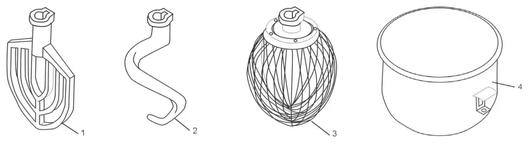
| Item | Description | Qty |
| 1 | Flat Beater | 1 |
| 2 | Dough Hook | 1 |
| 3 | Wisk | 1 |
| 4 | Bowl | 1 |
NOTES:
- Any agitator is easily installed by simply raising it onto the mixing axle, and rotating it clockwise on the shaft until it locks into place. To remove, raise the agitator on the shaft until it clears the lock and then rotate counter-clockwise and lower.
- All of the accessories are precisely fitted to the bowl, have rounded corners, and are easily removable for cleaning.
Operation Instructions
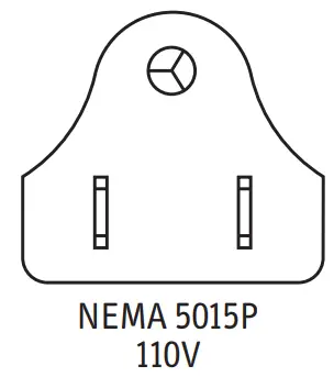
![]() Please ensure that your power supply matches your machine
Please ensure that your power supply matches your machine![]() For changing the speed* Please stop the machine first before changing speed in order to avoid damage to the gearbox. Also, make sure that the bowl is in a fully lifted position and the guard is closed.
For changing the speed* Please stop the machine first before changing speed in order to avoid damage to the gearbox. Also, make sure that the bowl is in a fully lifted position and the guard is closed.
- Slow Speed is the middle, dough hook set. The knob will be facing forward.
- Medium Speed is the bottom, flat beater set. The knob will be straight down.
- High Speed is the top, whisk setting. The knob will be straight up.
Mixing: Always use the correct attachment for the job.![]() A.Wisk: Suitable for mixing liquids and soft ingredients, can work at all speeds. Do not run for more than 15 minutes.
A.Wisk: Suitable for mixing liquids and soft ingredients, can work at all speeds. Do not run for more than 15 minutes.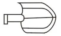 B. Flat Beater: Suitable for mixing dry ingredients, can work at low & medium speeds only. Do not use it at high speed. Do not run for more than 15 minutes.
![]() C. Dough Hook: Suitable for mixing dough, can work in low & medium speeds only. Do not use in high speed, and do not run for more than 20 minutes Absorption ratio must be more than 50%. Refer to mixer capacity chart.
C. Dough Hook: Suitable for mixing dough, can work in low & medium speeds only. Do not use in high speed, and do not run for more than 20 minutes Absorption ratio must be more than 50%. Refer to mixer capacity chart.
Mixer Capacity Chart
| Product | Agitator and Speed | Maximum Bowl Capacity |
| Bread and Roll Dough -60 % AR | Dough Hook – 1st only | 20 lb. |
| Heavy Bread Dough -55% AR | Dough Hook – 1st only | 15 lb. |
| Pizza Dough, Thin -40% AR | Not Recommended | – |
| Pizza Dough, Medium -50% AR | Not Recommended | – |
| Pizza Dough, Thick -60% AR | Not Recommended | – |
| Raised Donut Dough -65% AR | Dough Hook – 1st and 2nd | 8 lb. |
| Mashed Potatoes | Flat Beater | 12.5 lb. |
| Waffle or Hot Cake Batter | Flat Beater | 8 qt. |
| Egg Whites | Wire Whisk | 1 qt. |
| Whipped Cream | Wire Whisk | 2 qt. |
| Cake Batter | Flat Beater | 20 lb. |
When mixing dough ( pizza, bread, or bagels), check your “AR” absorption ratio – water weight divided by flour weight. Above capacities are based on 12% flour moisture at 70°F water temperature. If high gluten flour is used, reduce above dough batch size by 10%.
Example: If recipe calls for 5 lb. of water and 10 lb. of flour, then 5 divided by 10 = 0.50 x 100 = 50 %AR.
- 2nd Speed should never be used on mixtures with less than 50% AR.
- Do not use attachments on hub while mixing.
When calculating the correct size mixer for your application, here are some helpful weights & measures: - 8.3 lb. = 1 gallon of water – 2.08 lb. = 1 Quart.
Cleaning
![]() WARNING: DISCONNECT THE MACHINE FROM THE POWER SOURCE BEFORE CLEANING
WARNING: DISCONNECT THE MACHINE FROM THE POWER SOURCE BEFORE CLEANING
All new mixer bowls and accessories including whips, beaters, and dough hooks should be properly washed before use.
Wash with hot water and a mild soap solution and then rinse off with either a mild vinegar or soda solution and then rinse again with clean water. It is highly recommended this cleaning procedure is followed for bowls and accessories prior to whipping egg whites or whole eggs. The mixer should be cleaned daily with a clean damp cloth.
If the unit has not been used for some time, it is recommended that the procedure above is followed before mixer use.
It is important that the rear bowl lift guides are greased every three months to prevent corrosion.
Troubleshooting
| Trouble | Possible Causes | Solution |
| The axles can’t work when operating the machine | Poor contact with the electrical equipment | Check the Plug |
| The mixing bowl is out of position | Moving direction is not correct | Change |
| Leaks oil | Sealing washer is damaged | Change |
| Difficult to move the bowl up and down | Slideway is rusted | Clean the slideway and lubricate |
| The motor is overheated and speed is down | The voltage is not enough, or incorrect speed | Check the voltage or use lower speed |
| Noise and overheating | Poor lubrication | Add or change lubrication |
| Mixer touches bowl | The mixing device or bowl deformed | Repair or change the bowl or mixing device |
TRANSMISSION CASE
FIGURE 1
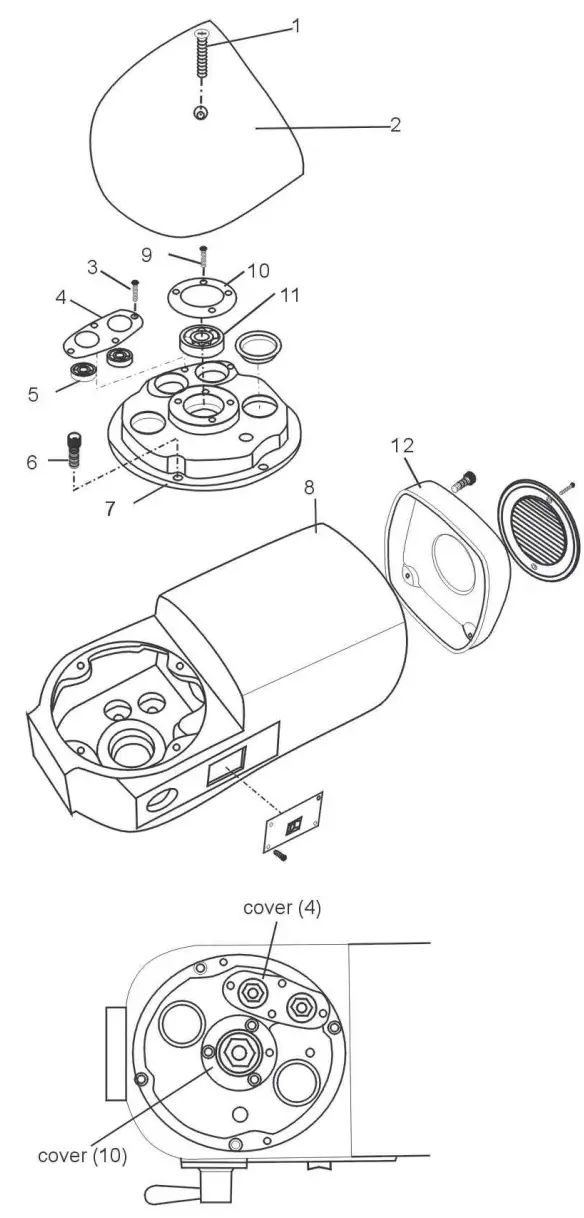
| ITEM | DESCRIPTION | QTY |
| 1 | Screw M6*45 | 1 |
| 2 | Cover | 1 |
| 3 | Screw M5*8 | 4 |
| 4 | Cover | 1 |
| 5 | Bearing 6201 | 2 |
| 6 | Screw M6*25 | 4 |
| 7 | End Cover | 1 |
| 8 | Body | 1 |
| 9 | Screw M5*8 | 3 |
| 10 | Cover | 1 |
| 11 | Bearing 6003 | 1 |
| 12 | Rear cover | 1 |
| NOTES: • The factory has provided superior lubricant for several years of use. If the mixer is repaired please ensure that the service technician replaces any lubricant lost or removed. | ||
PLANETARY SHAFT ASSEMBLY
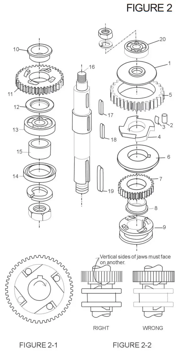
ITEM | DESCRIPTION | QTY |
| 1 | Baffle | 1 |
| 2 | Roller | 4 |
| 3 | Spring | 8 |
| 4 | Engager | 1 |
| 5 | Gear Ring | 1 |
| 6 | Dividing Ring | 1 |
| 7 | Joint Gear I | 1 |
| 8 | Bearing Ring | 1 |
| 9 | Joint | 1 |
| 10 | Bearing Ring | 1 |
| 11 | Joint Gear I | 1 |
| 12 | Ring | 1 |
| 13 | Bearing 6205 | 1 |
| 14 | Oil Seal Pd30*45*10 | 1 |
| 15 | Sleeve | 1 |
| 16 | Axle | 1 |
| 17 | Key 6*14 | 1 |
| 18 | Key 5*35 | 2 |
| 19 | Key 6*30 | 1 |
| 20 | Bearing | 1 |
| NOTES: • Be sure to install the correct position (see Figure 2-1) and lubricate all of the pins in the sleeve drive when reassembling. • Joint (9) must always be raised and lowered smoothly. Be sure joint sleeve as shown in Figure 2-2 • Check the oil seal (14), if serious oil leaks from the drip cup. | ||
TRANSMISSION SHAFT
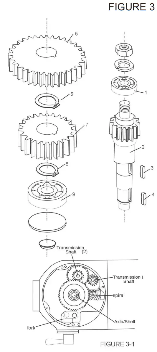
| ITEM | DESCRIPTION | QTY |
| 1 | Bearing | 1 |
| 2 | Transmission Axle | 1 |
| 3 | Key 5*11 | 1 |
| 4 | Key 5*11 | 1 |
| 5 | Gear | 1 |
| 6 | Stop Ring | 1 |
| 7 | Gear | 1 |
| 8 | Stop Ring | 1 |
| 9 | Bearing 6201 | 1 |
| NOTES: • At the center in the shaft unit. To the above gear is the gear shaft and gear shaft I (see figure 3-1) • C-type stop ring (6/8) has to be fixed when reassembling. • Be sure that the keys are inserted for each gear. | ||
WORM GEAR SHAFT ASSEMBLY
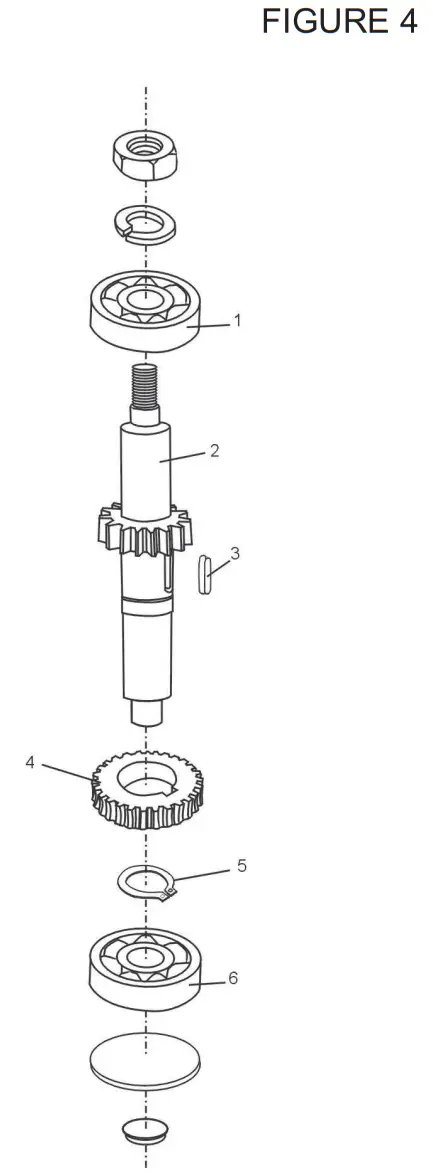
| ITEM | DESCRIPTION | QTY |
| 1 | Bearing 6201 | 1 |
| 2 | Gear Axle | 1 |
| 3 | Key 5*14 | 1 |
| 4 | Gear | 1 |
| 5 | Stop Ring | 1 |
| 6 | Bearing 6201 | 4 |
| NOTES: • C-Type stop ring (5) has to be fixed when reassembling. | ||
MOTOR UNIT
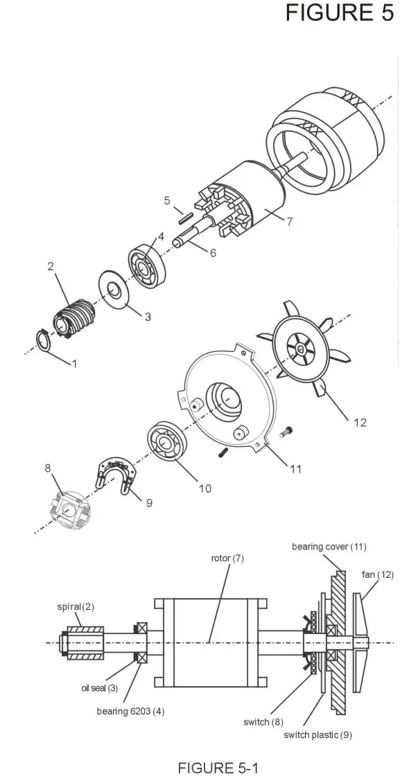
| ITEM | DESCRIPTION | QTY |
| 1 | Stop Ring | 1 |
| 2 | Worm Gear | 1 |
| 3 | Oil Seal | 1 |
| 4 | Bearing 6203 | 1 |
| 5 | Key 4*22 | 1 |
| 6 | Axle | 1 |
| 7 | Rotor | 1 |
| 8 | Governor | 1 |
| 9 | Governor Plate | 1 |
| 10 | Bearing 6203 | 1 |
| 11 | Bearing Cover | 1 |
| 12 | Fan | 1 |
| NOTES: • If the motor does not work, first verify the power source and connection. Next, check for damaged or faulty wiring or connections inside the mixer. A faulty motor may be the result of incorrect voltage, broken wires, or a defective cen- centrifugal governor. Motor damage may also be caused by bowel overload during mixing. • Motor set includes motor axle (6), rotor (7), and stator. • Figure 5-1 is component system diagrams of motor. | ||
SHIFTING MECHANISM
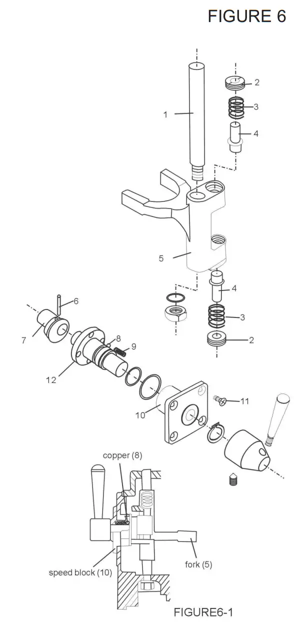
| ITEM | DESCRIPTION | QTY |
| 1 | Axle | 1 |
| 2 | Nut | 1 |
| 3 | Spring | 1 |
| 4 | Shaft | 1 |
| 5 | Fork | 1 |
| 6 | Pin 3*20 | 1 |
| 7 | Eccentricity Knot | 1 |
| 8 | Steel Ball | 3 |
| 9 | Speed Spring | 3 |
| 10 | Speed Block | 1 |
| 11 | Screw M5*10 | 1 |
| 12 | Shaft | 1 |
| NOTES: • The speed selector/shifting mechanism is designed for simplicity and reliability. It features three mixing speeds. | ||
STAND & BOWL LIFT UNIT
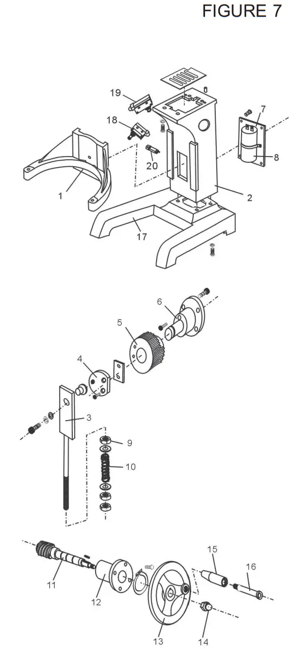
| ITEM | DESCRIPTION | QTY |
| 1 | Bowl Support | 1 |
| 2 | Columns | 1 |
| 3 | Slide | 1 |
| 4 | Plate | 1 |
| 5 | Gear | 1 |
| 6 | Support Seat | 1 |
| 7 | Capacitor Board | 1 |
| 8 | Capacitor 200uF | 1 |
| 9 | Nut M10 | 3 |
| 10 | Spring | 1 |
| 11 | Spiral | 1 |
| 12 | Bowl Lift Support | 1 |
| 13 | Handwheel | 1 |
| 14 | Nut M10 | 1 |
| 15 | Handle | 1 |
| 16 | Handle Screw | 1 |
| 17 | Machine Seat | 1 |
| 18 | Limit Switch of Safety Guard | 1 |
| 19 | Fluctuate Safety Switch | 1 |
| 20 | Overload Protection Switch | 1 |
| 21 | AC Contact Device | 1 |
| 22 | AC Contact Device Box | 1 |
BOWL LIFT UNIT
FIGURE 8
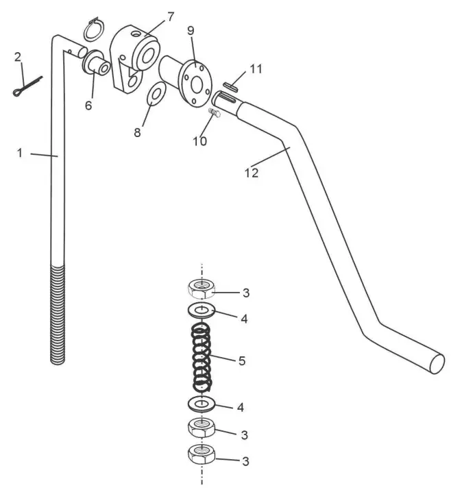
| ITEM | DESCRIPTION | QTY |
| 1 | Lifting Bar | 1 |
| 2 | Cotton Pin 3*30 | 1 |
| 3 | NutM10 | 3 |
| 4 | Flat Washer | 2 |
| 5 | Compression Spring | 1 |
| 6 | Little Knot | 1 |
| 7 | Lifting Handle Bracket | 1 |
| 8 | Flat Washer | 1 |
| 9 | Flange Knot | 1 |
| 10 | Screw M6*25 | 1 |
| 11 | Key 5*20 | 1 |
| 12 | Bowl Lift Handle | 1 |
PLANETARY ASSEMBLY
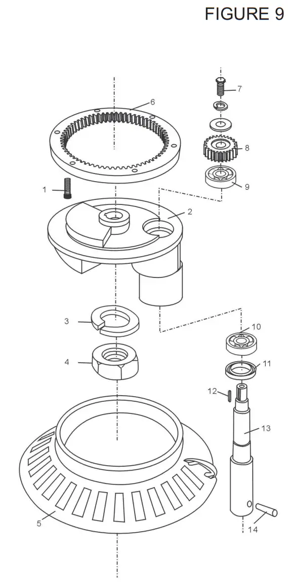
| ITEM | DESCRIPTION | QTY |
| 1 | Screw M6*45 | 6 |
| 2 | Turning Plate | 1 |
| 3 | Ring | 1 |
| 4 | Nut M20*1.5 | 1 |
| 5 | Safety Guard | 1 |
| 6 | Inner Gear | 1 |
| 7 | Screw M8*15 | 1 |
| 8 | Planetary Gear | 1 |
| 9 | Bearing 6203 | 1 |
| 10 | Bearing 6204 | 1 |
| 11 | Oil SealPd25*50*10 | 1 |
| 12 | Key 5*18 | 1 |
| 13 | Mixing Axle | 1 |
| 14 | Pin | 1 |
Electrical Diagram
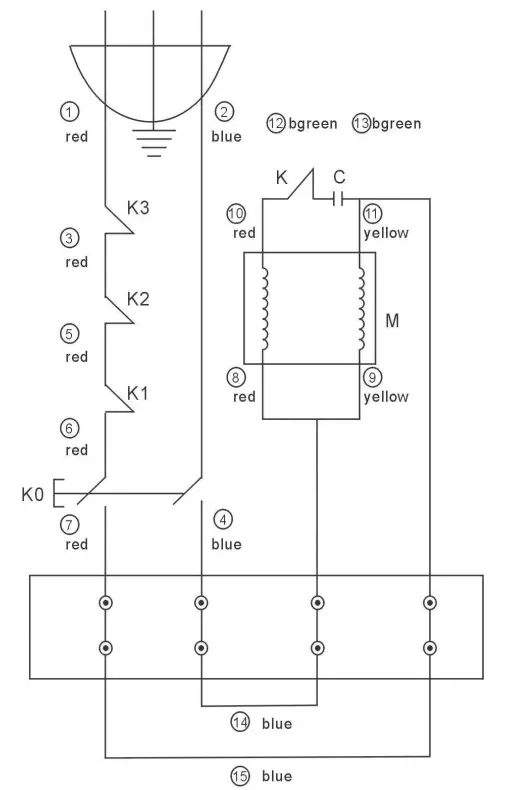
| KO-ELECTROMAGNETIC SWITCH |
| K1-SAFETY COVERING SWITCH |
| K2-FLUCTUATE SAFETY SWITCH |
| K3-OVERLOAD PROTECTION WATCH |
| K-SWITCH |
| C-CAPACITOR |
| M-MOTOR |
177MX20 SPECIFICATIONS
| Type | MX20 |
| Capacity | 20 QT. |
| Power Supply | 110V |
| Phase | 1 |
| Input Power | 1100W |
| Hertz | 60 Hz |
| Horsepower | 1 HP |
| Max. Flour Capacity | 20 LB. |
![]()
02/2022
www.AvantcoEquipment.com


