![]()
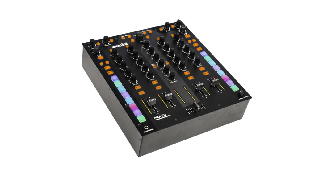
PMX-20
DIGITAL PERFORMANCE MIXER
USER MANUAL
WELCOME TO THE GEMINI FAMILY!
At Gemini, our highest priority is making your experience unforgettable.
Need help with setting up, troubleshooting, or looking for some tips?
We’re here for you, Monday through Friday 9 AM-5 PM EST.
![]() [email protected]
[email protected]![]() 1-844-GEMINI9
1-844-GEMINI9![]() www.geminisound.com
www.geminisound.com

SAFETY INSTRUCTIONS
- Read these Instructions.
- Keep these Instructions.
- Heed all Warnings.
- Follow all instructions.
- Do not use this apparatus near water.
- Clean only with dry cloth.
- Do not block any ventilation openings. Install in accordance with the manufacturer’s instructions.
- Do not install near any heat sources such as radiators, heat registers, stoves, or other apparatus (including amplifi ers) that produce heat.
- Do not defeat the safety purpose of the polarized plug. A polarized plug has two blades with one wider than the other. The wide blade is provided for your safety. If the provided plug does not fi t into your outlet, consult an electrician for the replacement of the obsolete outlet.
- Protect the power cord from being walked on or pinched, particularly at plugs, convenience receptacles, and the point where they exit from the apparatus.
- Only use attachments/accessories specifi ed by the manufacturer.
- Use only with the cart, stand, tripod, bracket, or table specifi ed by the manufacturer or sold with the apparatus. When a cart is used, use caution when moving the cart/apparatus combination to avoid injury from tip-over.
- Unplug this apparatus during lightning storms or when unused for long periods of time.
- Refer all servicing to qualifi ed service personnel. Servicing is required when the apparatus has been damaged in any way, such as power-supply cord or plug is damaged, liquid has been spilled or objects have fallen into the apparatus, the apparatus has been exposed to rain or moisture, does not operate normally, or has been dropped.
- WARNING: To reduce the risk of fi re or electric shock, do not expose this apparatus to rain or moisture.
- Since the device’s power cable is used as the primary disconnection device, the power cable should remain readily operable at all times.
- The ventilation should not be impeded by covering the ventilation openings with items, such as newspapers, tablecloths, curtains, etc.
- No naked fl ame sources, such as lighted candles, should be placed on the apparatus.
- The apparatus should be used in moderate climates.
- The apparatus shall not be exposed to dripping or splashing and no objects filled with liquids (such as drinks) shall be placed on the apparatus.
WARNING
To reduce the risk of electric shock, do not remove the cover (or back). There are no user-serviceable parts inside. Maintenance and repairs should be exclusively carried out by qualifi ed service personnel.
CAUTION
To reduce the risk of electric shock, do not remove the cover. No user-serviceable parts inside. Refer servicing to qualified service personnel only.

The warning triangle with an exclamation mark indicates important operating and maintenance instructions. The warning triangle with the lightning symbol indicates dangerous uninsulated voltage inside the unit, which may cause an electrical shock.
 To prevent electric shock, do not use this Polarized Plug with an extension cord, receptacle, or another outlet unless the blades can be fully inserted to prevent blade exposure.

Please ensure that you fi nd these accessories included with your PMX-20 Digital Performance Mixer with USB audio interface:
(1) PMX-20 Digital Mixer
(1) Power Cord
(1) USB Cable (to connect to a computer)
(1) Instruction Manual
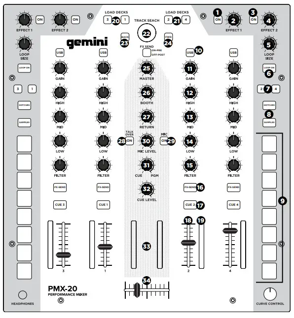
FUNCTION
TOP VIEW
- Effect 1 Button ON/OFF
Turns Effect 1 ON or OFF - Effect 1 Knob
Controls value of Effect 1 - Effect Button 2 ON/OFF
Turns Effect 2 ON or OFF - Effect Knob 2
Controls value of Effect 2 - Loop Size Encoder
Turn to increase or decrease loop size - Loop Button ON/OFF
Turns to loop for associated deck ON or OFF - Hotcues Mode Button
Switches buttons 1-8 to HOT CUE mode - Samples Mode Button
Switches buttons 1-8 into SAMPLES mode - Hotcue Buttons
Triggers or sets Hotcues - USB Button
Switches channel source from external to USB audio interface - Channel Gain Knob
Turn to change input gain of channel - High-Frequency EQ Knob
Turn to adjust the High EQ value - Mid Frequency EQ Knob
Turn to adjust the Mid EQ value - Low-Frequency EQ Knob
Turn to adjust the Low EQ value - Dual Pole (HP/LP) Filter Knob
• Turn to adjust fi lter for the selected channel
• Center – No Filter Effect
• Clockwise from the center – High-pass Filter
• Counter-Clockwise from the center – Low-pass filter - FX Send Button
Press to send channel audio to effects loop - CUE/PFL Button
Press to insert channel into Cue (PFL) bus - 45mm Channel Fader
Move to increase or decrease volume for the selected channel - Channel LED Meter
Shows the pre-fader level of the selected channel - Load Deck 1/3 Buttons
Loads selected track into the Deck 1 or Deck 3 Player - Load Deck 2/4 Buttons
Loads selected track into Deck 2 or Deck 4 Player - Track Search Encoder
Turn to scroll through library/Press to enter a directory - Back Button
Press to go back one directory - Forward Button
Press to go into the highlighted directory - Master Volume Knob
Turn to increase Master Output Volume - Booth Volume Knob
Turns to increase Booth Output Volume - FX Return Knob
Adds FX return signal back to Master Bus - Talkover Button
Lowers the volume of the non-microphone channels - Mic On/Off Button
Turns the mic channel on or off - Mic Level Knob
Turn to increase the volume of attached Microphone - Cue Split Knob
Splits cue between Cue bus and Program bus - Cue Level Knob
Turn to increase or decrease the volume of Cue bus - Master Bus LED Meter
Shows the level of Master bus - 45mm Crossfader
Move to select channel audio sent to Master bus
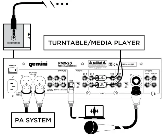
REARVIEW - Power Button
Turns mixer on or off - Master XLR (Balanced) Outputs
Professional-grade stereo outputs - Master RCA (Unbalanced) Outputs
Consumer quality Stereo outputs - Booth Output
Output for monitoring speakers - Record Output
Output for recording devices - USB Type-B Connector
To connect PMX-20 to a computer - CH4 Line/Phono Switch
Switch to control level of CH4 input - CH4 RCA Inputs
Input for CH4 Source - CH3 RCA Inputs
Input for CH3 Source - CH3 Line/Phono Switch
Switch to control the level of CH3 input - CH2 Line/Phono Switch
Switch to control the level of CH2 input - CH2 RCA Inputs
Input for CH2 Source - CH1 RCA Inputs
Input for CH1 Source - CH1 Line/Phono Switch
Switch to control the level of CH1 input - Microphone Input Combo Jack
Connect XLR or 1/4” TRS Dynamic
Microphone - FX Send Output
RCA Output for FX Send Loop - FX Return Input
RCA Input for FX Send Loop - IEC 3-Prong Mains Power connector
Mains AC Power connector - Ground for use with TT sources
- Kensington Lock Connection
Connect Kensington Lock to secure mixer
TOP VIEW
REARVIEW

CONNECTION DIAGRAM
COMPUTER CONNECTION
Be sure that the PMX-20 is connected to your computer via the included USB cable. (Consult Connection Diagram). The PMX-20 Mixer is a Class Compliant multi-channel audio and MIDI interface, with low latency multichannel soundcard. In OSX, no additional drivers are needed. In Windows, to get the best possible performance we recommend you download and install the Gemini ASIO drivers from the PMX-20 product page on www.geminisound.com. The PMX20 product page is also where you’ll find additional information and downloads for your PMX-20 mixer (MIDI confi Gura on files, etc.). Your PMX-20 mixer is capable of receiving firmware updates via the mini updater software, which is also available for download from the PMX-20 product page. It Is a good idea to download and run the updater software occasionally to verify that you have the latest version of the device firmware. Updates are provided regularly to fi x problems and add features.
OPERATIONAL MODES
MIXER MODE: The unit operates as a normal mixer (this is the default mode on power on). No computer is necessary – all external devices are processed by the PMX-20’s internal CPU. If connected by USB to an external computer, it is possible to send and receive MIDI for nearly all controls, and pressing the USB buttons above each channel will switch that channel to the internal soundcard instead of the connected external source.
DVS MODE: The user enters this mode by pressing and holding the USB button on H1 for about 10 seconds. Lights will blink indicating a mode change. In this mode, Channels 1 and 2 are the DVS channels, an audio interface is reconfi figured as a 4 in/4 out the interface, and Channels 3 and 4 work as pure MIDI controls.
Any open DVS software (like Virtual DJ for example) will be able to recognize and use the onboard audio interface. However, you may need to purchase the additional DVS functionality from your software developer.
FULL MIDI MODE: The user enters this mode by pressing and holding the USB button on CH2 for 10 seconds. The lights will blink to indicate a mode change. In this mode, the PMX-20 acts as a pure controller. The built-in audio interface is reconfi guard as an 8 out interface (4 stereo outputs). Channel and Master peak metering is driven by the audio interface. If you are mapping the PMX-20 into your own software instead of Virtual DJ, it may be necessary to set your operational mode BEFORE opening your software of choice.
USING THE FX LOOP
The FX Loop on the PMX-20 is designed to allow the use of external hardware effects. There is a stereo send and return. SEND: Sends are activated with the FX SEND buttons located above the CUE buttons on each channel strip. Pressing the FX SEND button sends the audio from the active channel(s) to the FX SEND output RCA jacks on the back of the PMX-20. It is also possible to change the sending behavior from PRE-FADER to POST FADER by using the switch just below the TRACK SEARCH knob in the middle channel. PRE-FADER means audio is sent from the channel after the GAIN knob but before the channel fader. POST FADER means audio is sent from the channel after the input GAIN, channel fader, and after the crossfader.
RETURN: This is how audio from the FX SEND makes its way back into the mixer. After being processed by your external effect, the processed signal comes in via the FX RETURN RCA jacks on the back of the PMX-20. Audio is then mixed into the master audio bus. In the center channel strip, the RETURN knob controls the amount of audio added to the master out.
CROSSFADER CURVE CONTROL
In the bottom right corner of the PMX-20 is a recessed knob labeled CURVE CONTROL. This controls the response of the crossfader, allowing anything from a slow mix to a sharp, fast transition. To adjust this parameter, push down on this pot (like a button) to extend it above the faceplate. Turn the knob to adjust. Full counterclockwise will produce the sharpest curve, and full clockwise will produce the smoothest mix.
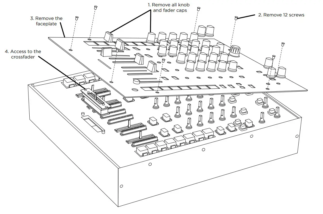
CROSSFADER REPLACEMENT
To replace the crossfader remove all power and signal cables from the mixer and, follow these steps:
- Remove all knob and fader caps. There are 38 pieces in all. You do not have to do anything with the buttons or switches.
- Remove the 12 faceplate screws using a small Phillips screwdriver.
- Remove the faceplate by pulling it straight up. This will expose the sub-chassis and give you access to the crossfader.
- The crossfader is connected to the mixer using a standard Molex-style connector.
Use care when separating the connector from the installed crossfader. - If you are installing a crossfader with adjustable parameters, it makes sense to make all adjustments needed BEFORE reinstalling the crossfader and putting the mixer back together. (PLEASE NOTE – When replacing the crossfader, the performance of the crossfader curve controls may change. Please take a moment to learn if the behavior of the curve controls has changed.)
TROUBLESHOOTING
UNIT WILL NOT POWER ON
- Check power cord is securely connected to the mains power and mixer
AUDIO IS DISTORTED (GENERAL) - Make sure channel GAIN is properly set
- If connected to a computer, verify GAIN and LEVEL are set correctly in the software
- Verify mixer channel and master levels are not in the red
- Make sure computer resources are not maxed out (CPU, memory, etc.)
ANALOG SOURCE AUDIO IS DISTORTED - Make sure the correct input level is selected (LINE or PHONO)
MICROPHONE IS NOT AUDIBLE - Raise MIC LEVEL until the mic is audible.
- Verify connected mic is a dynamic microphone
AUDIO INTERFACE IS NOT VISIBLE IN SOFTWARE - Make sure USB cable is connected to mixer and computer
- Re-install Gemini ASIO driver
- Make sure PMX-20 audio interface is selected in the software
NO MIDI DEVICES ARE AVAILABLE - Verify USB cable is connected to mixer and computer
- Make sure no other application has control of the MIDI interface
For all other issues, please contact GEMINI support at 1-844-GEMINI9
MIDI SPECIFICATION
| CONTROL NAME | TYPE OF DATA | MIDI OUT | MIDI IN |
| CH1 Hotcue 8 Button | Note | on – 90 01 7F/off – 80 01 00 | 90 01 ** |
| CH1 Sample 8 Button | Note | on – 90 09 7F/off – 80 09 00 | 90 09 ** |
| CH1 Hotcue 7 Button | Note | on – 90 02 7F/off – 80 02 00 | 90 02 ** |
| CH1 Sample 7 Button | Note | on – 90 0A 7F/off – 80 0A 00 | 90 0A ** |
| CH1 Hotcue 6 Button | Note | on – 90 03 7F/off – 80 03 00 | 90 03 ** |
| CH1 Sample 6 Button | Note | on – 90 0B 7F/off – 80 0B 00 | 90 0B ** |
| CH1 Hotcue 5 Button | Note | on – 90 04 7F/off – 80 04 00 | 90 04 ** |
| CH1 Sample 5 Button | Note | on – 90 0C 7F/off – 80 0C 00 | 90 0C ** |
| CH1 Hotcue 4 Button | Note | on – 90 05 7F/off – 80 05 00 | 90 05 ** |
| CH1 Sample 4 Button | Note | on – 90 0D 7F/off – 80 0D 00 | 90 0D ** |
| CH1 Hotcue 3 Button | Note | on – 90 06 7F/off – 80 06 00 | 90 06 ** |
| CH1 Sample 3 Button | Note | on – 90 0E 7F/off – 80 0E 00 | 90 0E ** |
| CH1 Hotcue 2 Button | Note | on – 90 07 7F/off – 80 07 00 | 90 07 ** |
| CH1 Sample 2 Button | Note | on – 90 0F 7F/off – 80 0F 00 | 90 0F ** |
| CH1 Hotcue 1 Button | Note | on – 90 08 7F/off – 80 08 00 | 90 08 ** |
| CH1 Sample 1 Button | Note | on – 90 20 7F/off – 80 20 00 | 90 20 ** |
| CH1 SAMPLE MODE Button* | Note | on – 90 21 7F/off – 80 21 00 | 90 21 ** |
| CH1 HOTCUE MODE Button* | Note | on – 90 22 7F/off – 80 22 00 | 90 22 ** |
| CH1 Loop On Button | Note | on – 90 23 7F/off – 80 23 00 | 90 23 ** |
| CH1 Loop Size Encoder | CC (Relative) | B0 24 ** | None |
| CH1 Eff ect 2 Knob | CC (Absolute) | B0 25 ** | None |
| CH1 Eff ect 2 On Button | Note | on – 90 26 7F/off – 80 26 00 | 90 26 ** |
| CH1 Eff ect 1 Knob | CC (Absolute) | B0 27 ** | None |
| CH1 Eff ect 1 Button | Note | on – 90 28 7F/off – 80 28 00 | 90 28 ** |
| CH2 Hotcue 8 Button | Note | on – 91 01 7F/off – 81 01 00 | 91 01 ** |
| CH2 Sample 8 Button | Note | on – 91 09 7F/off – 81 09 00 | 91 09 ** |
| CH2 Hotcue 7 Button | Note | on – 91 02 7F/off – 81 02 00 | 91 02 ** |
| CH2 Sample 7 Button | Note | on – 91 0A 7F/off – 81 0A 00 | 91 0A ** |
| CH2 Hotcue 6 Button | Note | on – 91 03 7F/off – 81 03 00 | 91 03 ** |
| CH2 Sample 6 Button | Note | on – 91 0B 7F/off – 81 0B 00 | 91 0B ** |
| CH2 Hotcue 5 Button | Note | on – 91 04 7F/off – 81 04 00 | 91 04 ** |
| CH2 Sample 5 Button | Note | on – 91 0C 7F/off – 81 0C 00 | 91 0C ** |
| CH2 Hotcue 4 Button | Note | on – 91 05 7F/off – 81 05 00 | 91 05 ** |
| CH2 Sample 4 Button | Note | on – 91 0D 7F/off – 81 0D 00 | 91 0D ** |
| CH2 Hotcue 3 Button | Note | on – 91 06 7F/off – 81 06 00 | 91 06 ** |
| CH2 Sample 3 Button | Note | on – 91 0E 7F/off – 81 0E 00 | 91 0E ** |
| CH2 Hotcue 2 Button | Note | on – 91 07 7F/off – 81 07 00 | 91 07 ** |
| CH2 Sample 2 Button | Note | on – 91 0F 7F/off – 81 0F 00 | 91 0F ** |
| CH2 Hotcue 1 Button | Note | on – 91 08 7F/off – 81 08 00 | 91 08 ** |
| CH2 Sample 1 Button | Note | on – 91 20 7F/off – 81 20 00 | 91 20 ** |
| CH2 SAMPLE MODE Button* | Note | on – 91 21 7F/off – 81 21 00 | 91 21 ** |
| CH2 HOTCUE MODE Button* | Note | on – 91 22 7F/off – 81 22 00 | 91 22 ** |
| CH2 Loop On Button | Note | on – 91 23 7F/off – 81 23 00 | 91 23 ** |
| CH2 Loop Size Encoder | CC (Relative) | B1 24 ** | None |
| CH2 Eff ect 2 Knob | CC (Absolute) | B1 25 ** | None |
| CH2 Eff ect 2 On Button | Note | on – 91 26 7F/off – 81 26 00 | 91 26 ** |
| CH2 Eff ect 1 Knob | CC (Absolute) | B1 27 ** | None |
| CH2 Eff ect 1 Button | Note | on – 91 28 7F/off – 81 28 00 | 91 28 ** |
| Load CH1 Button | Note | on – 94 40 7F/off – 84 40 00 | 94 40 ** |
| Load CH2 Button | Note | on – 94 41 7F/off – 84 41 00 | 94 41 ** |
| Load CH3 Button | Note | on – 94 44 7F/off – 84 44 01 | 94 44 ** |
| Load CH4 Button | Note | on – 94 45 7F/off – 84 45 01 | 94 45 ** |
| Track Search Encoder (TURN) | CC (Relative) | B4 42 ** | None |
| Track Search Encoder (PUSH) | Note | on – 94 42 7F/off – 84 42 00 | None |
| Browser Back Button | Note | on – 94 43 7F/off – 84 43 00 | 94 43 ** |
| Browser Fwd Button | Note | on – 94 46 7F/off – 84 46 00 | 94 46 ** |
| Master Volume Knob | CC (Absolute) | B4 50 ** | None |
| Booth Volume Knob | CC (Absolute) | B4 51 ** | None |
| Mic Volume Knob | CC (Absolute) | B4 52 ** | None |
| Cue Split Knob | CC (Absolute) | B4 53 ** | None |
| Cue Volume Knob | CC (Absolute) | B4 54 ** | None |
| Master Out CH1 LED Array | CC (Absolute) | None | B4 55 ** |
| Master Out CH2 LED Array | CC (Absolute) | None | B4 56 ** |
| Crossfader | CC (Absolute) | B4 60 ** | None |
| CH1 LED Array | CC (Absolute) | None | B0 30 ** |
| CH1 Volume Fader | CC (Absolute) | B0 31 ** | None |
| CH1 Cue Button | Note | on – 90 32 7F/off – 80 32 00 | 90 32 ** |
| CH1 Filter Knob | CC (Absolute) | B0 33 ** | None |
| CH1 Low EQ Knob | CC (Absolute) | B0 34 ** | None |
| CH1 Mid EQ Knob | CC (Absolute) | B0 35 ** | None |
| CH1 High EQ Knob | CC (Absolute) | B0 36 ** | None |
| CH1 Gain Knob | CC (Absolute) | B0 37 ** | None |
| CH2 LED Array | CC (Absolute) | None | B1 30 ** |
| CH2 Volume Fader | CC (Absolute) | B1 31 ** | None |
| CH2 Cue Button | Note | on – 91 32 7F/off – 81 32 00 | 91 32 ** |
| CH2 Filter Knob | CC (Absolute) | B1 33 ** | None |
| CH2 Low EQ Knob | CC (Absolute) | B1 34 ** | None |
| CH2 Mid EQ Knob | CC (Absolute) | B1 35 ** | None |
| CH2 High EQ Knob | CC (Absolute) | B1 36 ** | None |
| CH2 Gain Knob | CC (Absolute) | B1 37 ** | None |
| CH3 LED Array | CC (Absolute) | None | B2 30 ** |
| CH3 Volume Fader | CC (Absolute) | B2 31 ** | None |
| CH3 Cue Button | Note | on – 92 32 7F/off – 82 32 00 | 92 32 ** |
| CH3 Filter Knob | CC (Absolute) | B2 33 ** | None |
| CH3 Low EQ Knob | CC (Absolute) | B2 34 ** | None |
| CH3 Mid EQ Knob | CC (Absolute) | B2 35 ** | None |
| CH3 High EQ Knob | CC (Absolute) | B2 36 ** | None |
| CH3 Gain Knob | CC (Absolute) | B2 37 ** | None |
| CH4 LED Array | CC (Absolute) | None | B3 30 ** |
| CH4 Volume Fader | CC (Absolute) | B3 31 ** | None |
| CH4 Cue Button | Note | on – 93 32 7F/off – 83 32 00 | 93 32 ** |
| CH4 Filter Knob | CC (Absolute) | B3 33 ** | None |
| CH4 Low EQ Knob | CC (Absolute) | B3 34 ** | None |
| CH4 Mid EQ Knob | CC (Absolute) | B3 35 ** | None |
| CH4 High EQ Knob | CC (Absolute) | B3 36 ** | None |
| CH4 Gain Knob | CC (Absolute) | B3 37 ** | None |
| CURVE XFADER Knob | CC (Absolute) | B4 72 ** | None |
| ** ADDITIONAL NOTES |
| See RGB Color Chart for values |
| See RGB Color Chart for values |
| See RGB Color Chart for values |
| See RGB Color Chart for values |
| See RGB Color Chart for values |
| See RGB Color Chart for values |
| See RGB Color Chart for values |
| See RGB Color Chart for values |
| See RGB Color Chart for values |
| See RGB Color Chart for values |
| See RGB Color Chart for values |
| See RGB Color Chart for values |
| See RGB Color Chart for values |
| See RGB Color Chart for values |
| See RGB Color Chart for values |
| See RGB Color Chart for values |
| 00=OFF/01=ON/02=SLOW BLINK/03=FAST BLINK/7F=ON |
| 00=OFF/01=ON/02=SLOW BLINK/03=FAST BLINK/7F=ON |
| 00=OFF/01=ON/02=SLOW BLINK/03=FAST BLINK/7F=ON |
| 00=OFF/01=ON/02=SLOW BLINK/03=FAST BLINK/7F=ON |
| 00=OFF/01=ON/02=SLOW BLINK/03=FAST BLINK/7F=ON |
| See RGB Color Chart for values |
| See RGB Color Chart for values |
| See RGB Color Chart for values |
| See RGB Color Chart for values |
| See RGB Color Chart for values |
| See RGB Color Chart for values |
| See RGB Color Chart for values |
| See RGB Color Chart for values |
| See RGB Color Chart for values |
| See RGB Color Chart for values |
| See RGB Color Chart for values |
| See RGB Color Chart for values |
| See RGB Color Chart for values |
| See RGB Color Chart for values |
| See RGB Color Chart for values |
| See RGB Color Chart for values |
| 00=OFF/01=ON/02=SLOW BLINK/03=FAST BLINK/7F=ON |
| 00=OFF/01=ON/02=SLOW BLINK/03=FAST BLINK/7F=ON |
| 00=OFF/01=ON/02=SLOW BLINK/03=FAST BLINK/7F=ON |
| 00=OFF/01=ON/02=SLOW BLINK/03=FAST BLINK/7F=ON |
| 00=OFF/01=ON/02=SLOW BLINK/03=FAST BLINK/7F=ON |
| 00=OFF/01=ON/02=SLOW BLINK/03=FAST BLINK/7F=ON |
| 00=OFF/01=ON/02=SLOW BLINK/03=FAST BLINK/7F=ON |
| 00=OFF/01=ON/02=SLOW BLINK/03=FAST BLINK/7F=ON |
| 00=OFF/01=ON/02=SLOW BLINK/03=FAST BLINK/7F=ON |
| No MIDI Feedback |
| 00=OFF/01=ON/02=SLOW BLINK/03=FAST BLINK/7F=ON |
| 00=OFF/01=ON/02=SLOW BLINK/03=FAST BLINK/7F=ON |
| See LED ARRAY FEEDBACK GUIDE |
| See LED ARRAY FEEDBACK GUIDE |
| 00-7F – All values should be expressed through length of travel |
| See LED ARRAY FEEDBACK GUIDE |
| 00=OFF/01=ON/02=SLOW BLINK/03=FAST BLINK/7F=ON |
| See LED ARRAY FEEDBACK GUIDE |
| 00=OFF/01=ON/02=SLOW BLINK/03=FAST BLINK/7F=ON |
| See LED ARRAY FEEDBACK GUIDE |
| See LED ARRAY FEEDBACK GUIDE |
| 00=OFF/01=ON/02=SLOW BLINK/03=FAST BLINK/7F=ON |
| 00-7F – All values should be expressed through length of travel |
AUDIO SPECIFICATION
| INPUTS | |
| Line | 150mV, 27 KOhm |
| Phono | 3mV, 47 KOhm |
| Microphone | 1.5mV, 1 KOhm Balanced |
| OUTPUTS | |
| Max | 20V Peak to Peak |
| Record | 225mV, 5 KOhm |
| GENERAL | |
| Frequency Response Distortion | 20Hz – 20KHz +/-2dB |
| S/N Ratio | <0.02% |
| Headphone Impedance | 16 Ohm |
| Power | 100-240 VAC 50~60Hz |
Specifi cations are subject to change without notifi cation for improvement.
RGB COLOR CHART (MIDI)
| VALUE | COLOR |
| 0 | OFF |
| 1 | Solid Green |
| 2 | Blinking Green |
| 3 | Solid Red |
| 4 | Blinking Red |
| 7 | Solid Blue |
| 8 | Blinking Blue |
| 0B | Solid Yellow |
| 0C | Blinking Yellow |
| 0F | Solid Light Blue |
| 20 | Blinking Light Blue |
| 25 | Solid Magenta |
| 26 | Blinking Magenta |
| 2D | Solid White |
| 2E | Blinking White |
WARRANTY AND REPAIR:
All Gemini products are designed and manufactured to the highest standards in the industry. With proper care and maintenance, your product will provide years of reliable service.
LIMITED WARRANTY
A. Gemini guarantees its products to be free from defects in materials and workmanship for one (1) year from the original purchase date. Exceptions: Laser assemblies on CD
Players, cartridges, and crossfaders are covered for 90 days.
B. This limited warranty does not cover damage or failure caused by abuse, misuse, abnormal use, faulty installation, improper maintenance or any repairs other than those provided by an authorized Gemini Service Center.
C. There are no obligations of liability on the part of Gemini for consequential damages arising out of or in connection with the use or performance of the product or other indirect damages with respect to loss of property, revenues, of profi t, or costs of removal, installation, or reinstallation. All implied warranties for Gemini, including implied warranties for fitness, are limited in duration to one (1) year from the original date of purchase unless otherwise mandated by local statutes.
RETURN/REPAIR
A. In the U.S.A., please call our helpful Customer Service Representatives at (732) 346-0061, and they will be happy to give you a Return Authorization Number (RA#) and
the address of an authorized service center closest to you.
B. After receiving an RA#, include a copy of the original sales receipt, with the defective product and a description of the defect. Send by insured freight to: Gemini and use the address provided by your customer service representative. Your RA# must be written on the outside of the package or processing will be delayed indefi nicely!
C. Service covered under warranty will be paid for by Gemini and returned to you. For non-warrantied products, Gemini will repair your unit after payment is received. Repair charges do not include return freight. Freight charges will be added to the repair charges.
D. On warranty service, you pay for shipping to Gemini, we pay for return shipping within the continental United States. Alaska, Hawaii, Puerto Rico, Canada, Bahamas, and the Virgin Islands will be charged for freight. E. Please allow 2-3 weeks for the return of your product. Under normal circumstances, your product will spend no more than 10 working days at Gemini. We are not responsible for shipping times.
IN THE USA:
If you experience problems with this unit, call 732-346-0061 for Gemini customer service. Do not attempt to return this equipment to your dealer.
Parts of the design of this product may be protected by worldwide patents. Information in this manual is subject to change without notice and does not represent a commitment on the part of the vendor. Gemini shall not be liable for any loss or damage whatsoever arising from the use of information or any error contained in this manual. No part of this manual may be reproduced, stored in a retrieval system or transmitted, in any form or by any means, electronic, electrical, mechanical, optical, chemical, including photocopying and recording, for any purpose without the express written permission of Gemini. It is recommended that all maintenance and service on this product is performed by Gemini or its authorized agents. Gemini will not accept liability for loss or damage caused by maintenance or repair performed by unauthorized personnel.
Gemini Worldwide Headquarters
107 Trumbull Street, Building F8 • Elizabeth,
NJ 07206 • USA • Tel: (732)346-0061 • Fax: (732)346-0065
© Innovative Concepts and Design LLC, All Rights Reserved.
Register your product online at WWW.GEMINISOUND.COM to be eligible for great prize giveaways!
References
 Gemini Sound: DJ, Pro Audio, Home Audio. Free Shipping over $50 American Express Apple Pay Diners Club Discover Facebook Pay Google Pay Mastercard PayPal Shop Pay Venmo Visa
-
Gemini Sound: DJ, Pro Audio, Home Audio. Free Shipping over $50 American Express Apple Pay Diners Club Discover Facebook Pay Google Pay Mastercard PayPal Shop Pay Venmo Visa


