vetus PFWS Pressurized-Water System
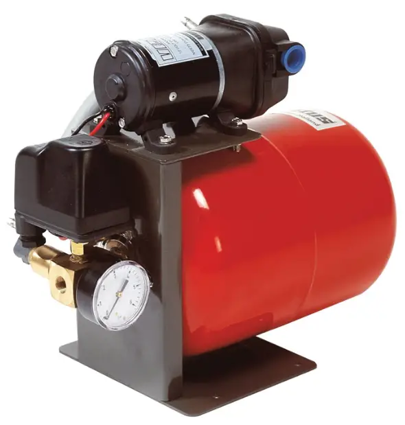
Introduction
The pressure tank with the rubber membrane in the pressurized water system ensures that a small quantity of water is immediately available under pressure for the water system.
As a result, the pump motor is not switched on each time water is tapped and a regular flow of water is available in your boat. The rubber used for the membrane will not give off any dangerous materials in the water.
Following the recommendations below will result in a longer life and better performance of your pressurized water system.
- Ensure that the water supply tank is always full; although the pump can still run when dry, this will prevent unnecessary dry running without the pressure tank being filled.
- Check that the battery voltage is correct.
- Battery voltage loss can be reduced by using cables of sufficient cross sectional area.
- Ensure that the pressurized water system is properly prepared for winter before the temperature falls below zero. Otherwise, irreparable damage may be caused to the system.
- Carry out the maintenance described regularly.
Installation
Setting up the pressurized water system
- The space where the pressurized water system is installed must be dry and well ventilated.
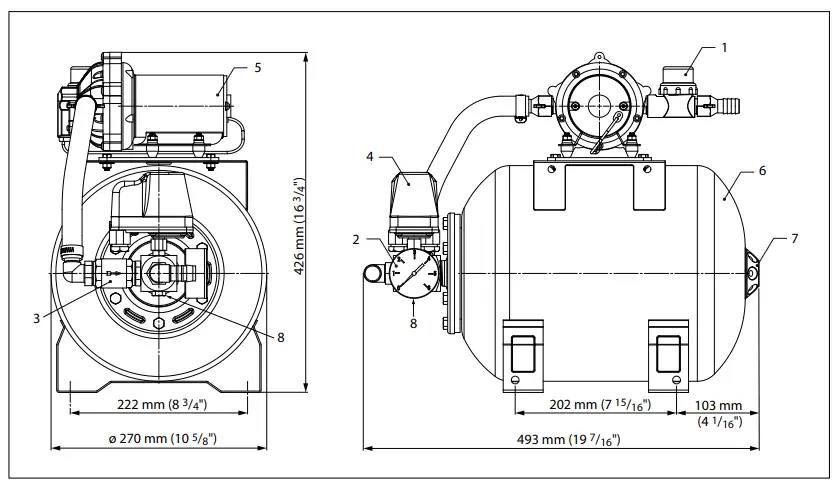
- When selecting a place for the installation, make sure that there is enough room for carrying out maintenance work. The water filter (principal dimensions, 1, page 19), drain plug (principal dimensions, 8), and the measuring/filler valve (Schräder valve) (principal dimensions, 7) of the air cushion must be easily accessible.
- To prevent noise and vibration, the pressurized water system should not be fitted directly to a bulkhead or tank wall.
- The pressurized water system can be mounted in a variety of positions; however the drain plug must never be in the highest position.
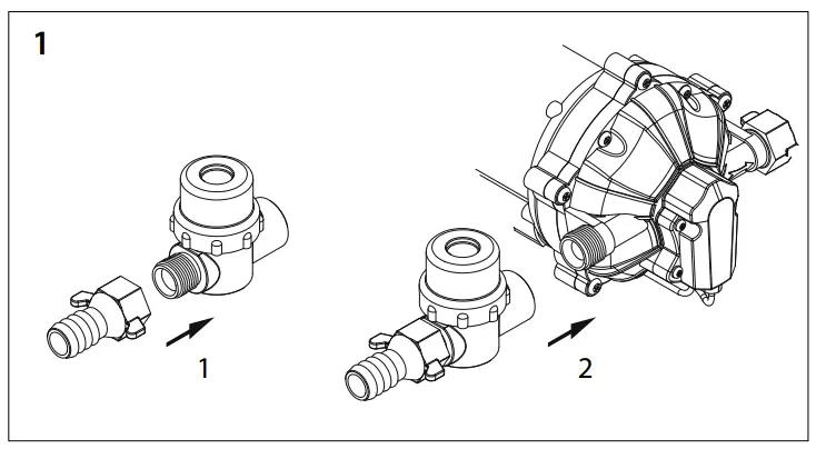
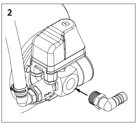
Installing the system
- Fit the filter to the inlet side of the pressurized water system (drawing 1), and the right-angle hose connector piece to the outlet side (drawing 2).
- Connect up the pressurized water system as shown in the drawing (drawing 3). For the piping, use a good quality hose which can accommodate a pressure of at least 8 Bar (116 psi), and an internal diameter 19 mm (3/4”).
- Secure the hose with stainless steel hose clamps.
If the system is installed using stainless steel or copper piping, the pressurized water system must still be connected using short sections of hose.
Electrical Installation
The minimum cross-section for the connecting cables is 2.5 mm2 (AWG 14). Voltage loss between battery and pressurized water system must not be more than 10% of the supply voltage.
In a 12 Volt pressurized water system with a total cable length (positive and negative cable together) greater than 10 m (model PFWS1219), use a cable with a cross-section of 4 mm2 (AWG 12).
A main switch and fuse* must be incorporated in the positive cable.
- Check that the voltage stated on the identification plate is the same as the battery voltage.
- Connect the system as shown in chapter 7, page 17.
- Install a relay to operate the 12 Volt Water Pressure System PFWS1219.
Fuse:
Model PWFS1219: 25 A for 12 Volt system
Model PWFS2419: 15 A for 24 Volt system
Starting the pressurized water system
When starting the pressurized water system, ensure that there is sufficient water in the tank and check that the drain plug is fitted.
- Open all taps; both hot and cold water.
- Switch the pump main switch on
- Close the taps as soon as the water is free of air.
- Check connections for leaks.
- Check the pressure at which the pump is switched on and off. If necessary, reset the pressure switch; see ‘Maintenance.
For efficient operation the pre-pressure of the air cushion in the tank must be about 0.2 Bar (3 psi) less than the pump switch pressure. Check this pressure and adjust if necessary; see ‘Maintenance’.
Winter Preparation
The whole water system, including the pressurized water system, should always be drained. Never fill the water system with antifreeze, it is very poisonous!
Draining the pressurized water system
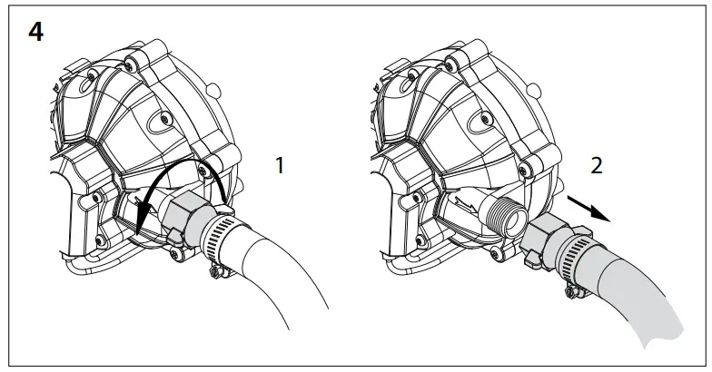
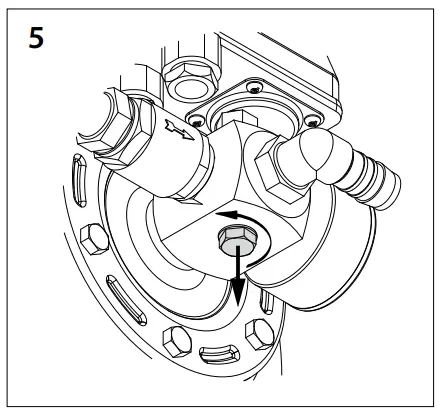
- Loosen the hose on the pressure side of the pump (drawing 4) and take the drain tap from the connector piece (drawing 5).
- Allow the pipes and pressure tank to drain empty. Then let the pump run for a time without any water input.
Maintenance
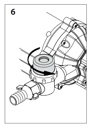
Cleaning the Water Filter
- Unscrew and remove the cover (drawing 6).
- Clean the filter element thus exposed.
- Refit the cover.
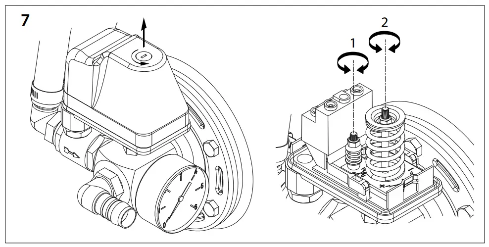
Checking and Adjusting the Pressure Switch (drawing 7)
Switch on pressure:
- Open a tap a quarter of a turn only. As the water runs out slowly the pressure will reduce. Now watch the manometer for the pressure at which the pump is switched on.
Increase switch-on pressure : Turn nut 2 to the right.
Decrease switch-on pressure : Turn nut 2 to the left.
Switch-off pressure:
- Leave the tap open quarter of a turn, so that the water pressure in the tank increases slowly. Now watch the manometer to read the pressure at which the pump is switched off.
Increase switch-off pressure: Turn nut 1 to the right.
Decrease switch-off pressure: Turn nut 1 to the left
N.B. Nut 1 adjusts the difference between switch-on and switch-off pressure. After resetting the switch-on pressure, the switch-off pressure must also be adjusted again.
Checking and pressurizing Pre-pressure and Air Cushion
- Remove the protective cap, turn to the left and check pressure with a tyre air pressure meter.
Reduce pressure: Push the Schräder valve pin in; air will now escape. Increase pressure: Connect a car tyre pump to the valve and bring the air cushion to the required pressure.
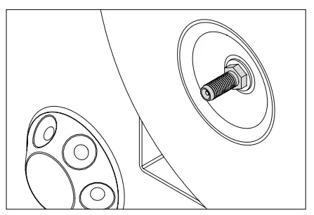
Replacing the Membrane
Under normal circumstances the membrane should never need replacement. However if it does leak, replace as follows:
- Ensure that the whole system is de-pressurized.
- Remove the hose between pump and T-piece, remove the 6 bolts holding the flange to the top of the tank and remove flange complete with T-piece.
- Remove the old membrane, refit a new one and reassemble in
reverse order to the above.
Technical data
| Type | PFWS1219 | PFWS2419 |
| Electric motor, type | Permanent magnet DC motor | |
| Voltage | 12VOC | 24VOC |
| Current at 0.7 Bar (10 psi) | 15 Amp | 8Amp |
| Pump, type | Self -priming 5 valve diaphragm pump | |
| Capacity at 2 Bar (30 psi) | 20 litres/ min (4.4 Imp.Gallon) | |
| Max. pressure | 4.2 Bar (61 psi) | |
| Maximum riser height | 1.8 m (6 ft) | |
| Filter, type | ln_line | |
| Mesh size | SO Mesh | |
| Pressure switch | ||
| Settings, | ||
| Switch -o n pressure | 1.4 Bar (20 psi) | |
| Switch -off pressure | 2.8 Bar (40.6psi) | |
| Range, | ||
| Min. switch-on pressure | 1 Bar (14.5 psi) | |
| Max. switch off pressure | 5 Bar (72.5 psi) | |
| Manometer | ||
| Meter range | 0 to 6 Bar (O- 87 p si) | |
| Pressure tank | ||
| Capacity | 19 lit res (4.2 Imp.Gallon) | |
| Pre-pressure, air cushion | 1.2 Bar (17.4psi) | |
| Connections, Hose | 19 mm (3/4″) | |
| Water temperature | 0 to 50 degrees C.(32 to 122 degrees F.) | |
| Weight | 9.5 kg (20.9 lb) | |
| 1 | Water tank |
| 2 | Pressurized water system |
| 3 | Boiler |
| 4 | (Mixer) Tap |
| 5 | Water filter |

Wiring diagram
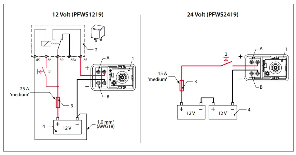
| A | Red |
| B | Black |
| 1 | Pressure switch |
| 2 | Main switch |
| 3 | Fuse |
| 4 | Battery |
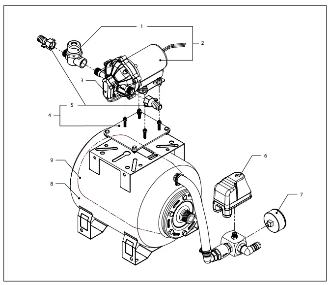
| pos. | qty | part | description |
| 1 | 1 | WP02 | Water filter |
| 2 | 1 | WP1220B | Fresh water pump 12 V |
| 1 | WP2420B | Fresh water pump 24 V | |
| 3 | 1 | WP20PS | Pressure switch |
| 4 | 1 | VP000065 | Adapter plate set |
| 5 | 1 | VP000066 | Set of hose connection |
| 6 | 1 | HYDRF008 | Pressure switch |
| 7 | 1 | HYDRF019 | Manometer |
| 8 | 1 | HYDRF046 | Pressure tank |
| 9 | 1 | HYDRF047 | Membrane |
Principal Dimensions
- Water filter
- Manometer
- Non-return valve
- Pressure switch
- Pump
- Pressure tank
- Air cushion measuring/filler valve
- Drain plug

Customer Support
Fokkerstraat 571 – 3125 BD Schiedam – Holland
Tel.: +31 (0)88 4884700 – [email protected] – www.vetus.com