vetus TMWQ Electric Marine Toilets
Introduction
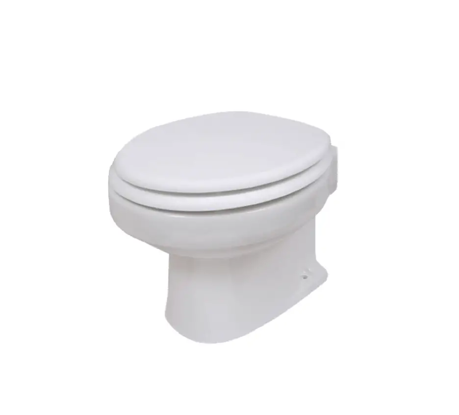
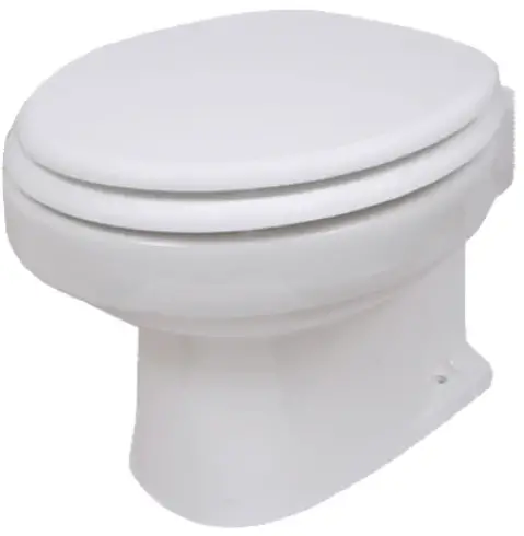
The VETUS ‘TM…’ toilets are marine toilets with an integrated pump system. With correct installation and operation, these toilets function like a normal toilet.
![]() Note!
Note!
These VETUS toilets may only be used for pumping and removal of faeces and toilet paper.
These toilet are not suitable for pumping other objects such as cotton wool pads, tampons, sanitary towels, condoms or hair, or for pumping out fluids like oil. This could cause damage!
![]() Tip
Tip
Make sure you always have a pair of rubber gloves on board for cleaning and maintenance.
Safety
Ensure that the power supply is switched off during maintenance or repairs.
Never put your hands in the hole in the toilet bowl. The blades are not covered!
Included in the delivery
- Closet (TM…), incl. set of fasteners
- Toilet seat. incl. set of fasteners
- Hose clamps
- Reduction elbows
1 Water supply hose
1 Manual
The control panel (TMWBP) and the control switch (TMWBS) are not included in the delivery of the toilet and must be ordered separately
Installation
General
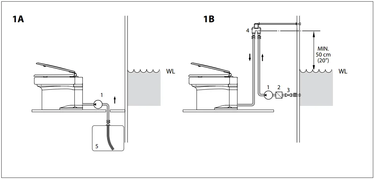
See page 37 for installation examples.
Always install the toilet in accordance with the applicable regulations of the country concerned. In some areas, it may not be permitted to pump waste straight from the toilet into the water!
- Decide where the toilet is going to be.
It will need to be fixed to a properly solid, flat base to avoid point concentrated loading, which could cause the toilet bowl to crack.
Discharge
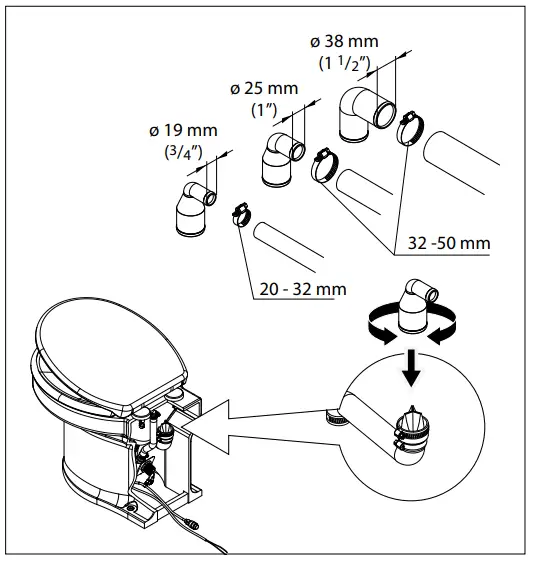
- Position the reducing piece (ø 19, ø 25 or ø 38 mm) in the discharge connection.
- Fix the reducing piece using the hose clamp.
- Fit the discharge hose (ø 19, ø 25 or ø 38 mm).
The reducing piece can be fitted in any position so that the discharge hose can be led to the left, right, or back as required.
For the discharge pipe use a 19, 25 or 38 mm internal diameter hose.
E.g. ‘VETUS impermeable “no smell” sanitary hose’.
Art. code:
SAHOSE19: VETUS impermeable “no smell” sanitary hose ø 19 mm,
SAHOSE25: VETUS impermeable “no smell” sanitary hose ø 25 mm,
SAHOSE38: VETUS impermeable “no smell” sanitary hose ø 38 mm - Fix the outlet with clamps.
If necessary fit an extra sheet of multiplex under the floor to reinforce it.
- Place the toilet in the position required.
- Determine the position of the fitting holes. Use the toilet as a template for this.
- Make all the connections as described in sections 4.2 to 4.6.
- Secure the toilet to the deck as described in 4.7.

Water supply
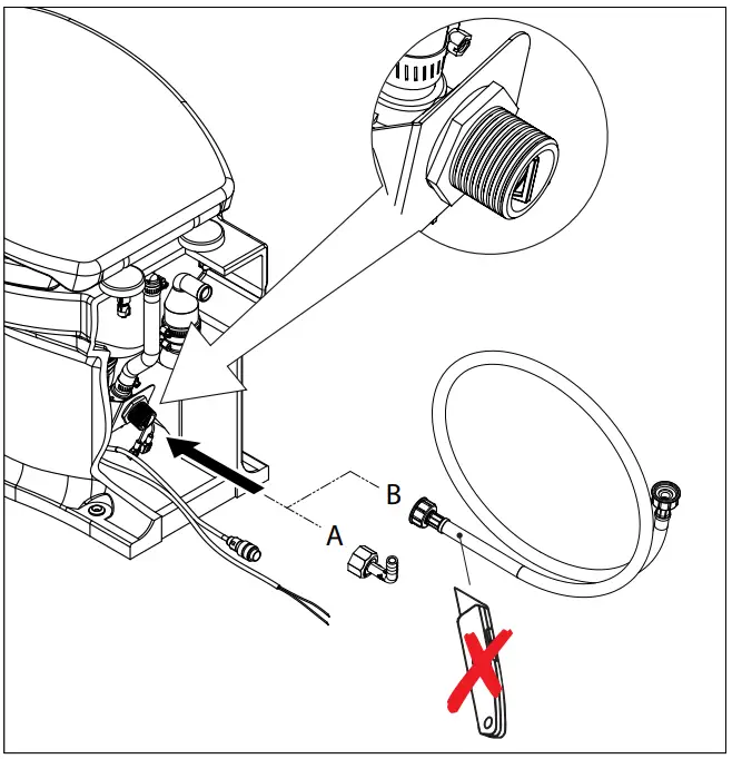
- Fit a ball valve with 3/4” external connection to the water supply and make sure that this will always be accessible (for water inlet hose B) or a 13 mm hose connection (connect this to hose connection A using a 13 mm water hose).
If there is already a pressurized water system on board the supply hose can be connected to this system. The pressure must be at least 1.5 bar; (21 psi) this is the minimum pressure required to allow the toilet to function properly.
If the water pressure system is less than 1.5 bar (21 psi) or if raw water is to be used then a supply pump with capacity of at least 10 liters/ minute (2.2 Imp. Gal/min; 2.7 US Gal/min) must be fitted in the water supply pipe.
If raw water is to be used this must be properly filtered.
An external water pump can be connected as an option. Use the yellow and green connection wires.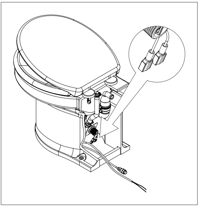
- Connect the flexible water supply hose to the ball valve on the water supply
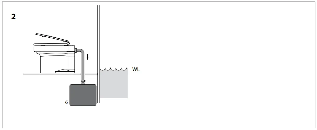
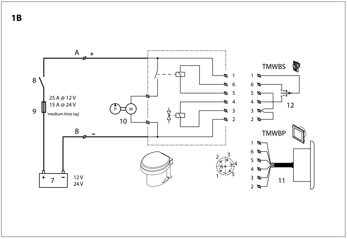
Prevention of siphoning
If the toilet is below or less than 50 cm(20”) above the waterline there is a danger of water siphoning back into the toilet (supply pipe). An air vent must be fitted at the highest point in the supply pipe in order to prevent siphoning (see the installation example 1B, see page 37).
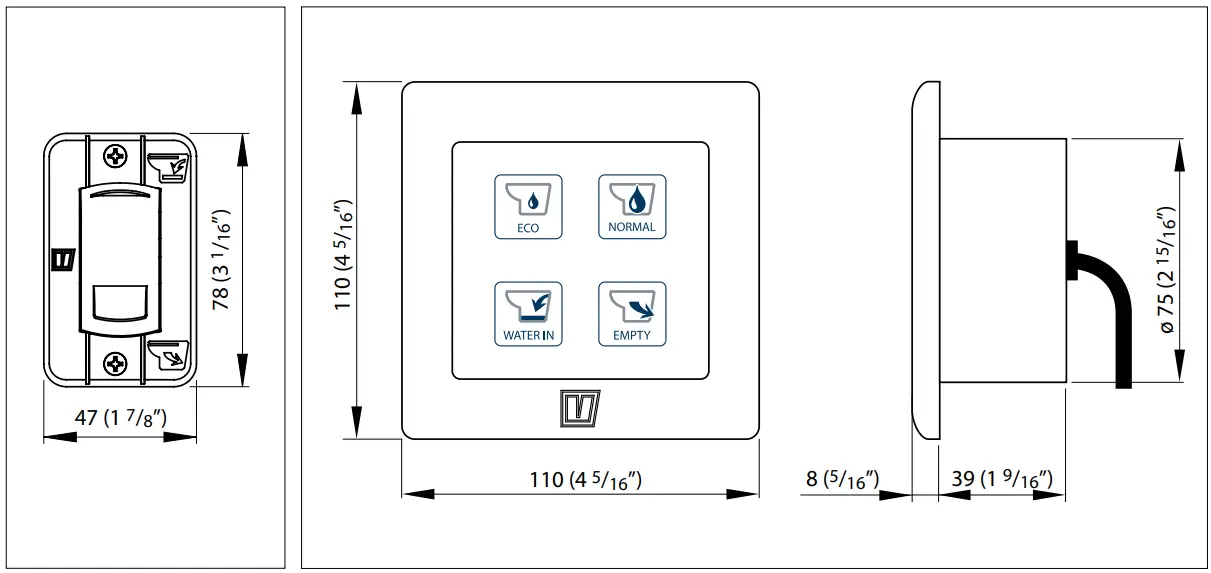
Control panel or control switch
TMWBP:
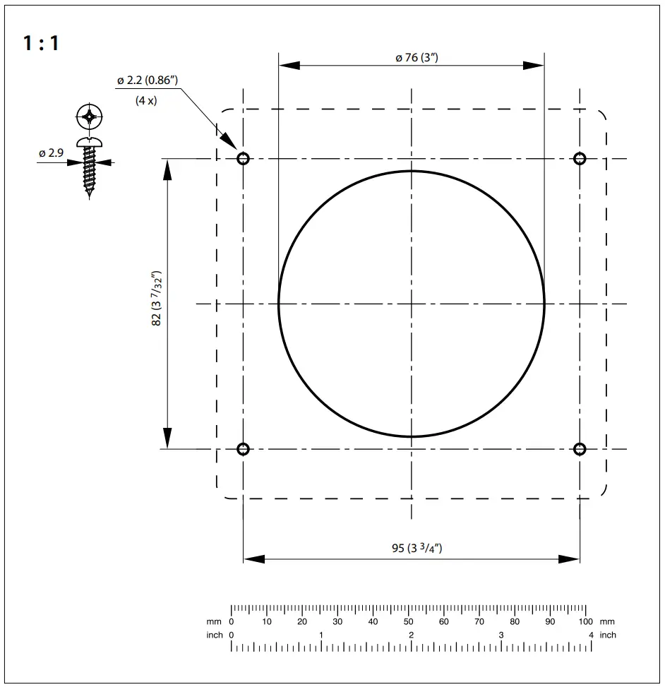
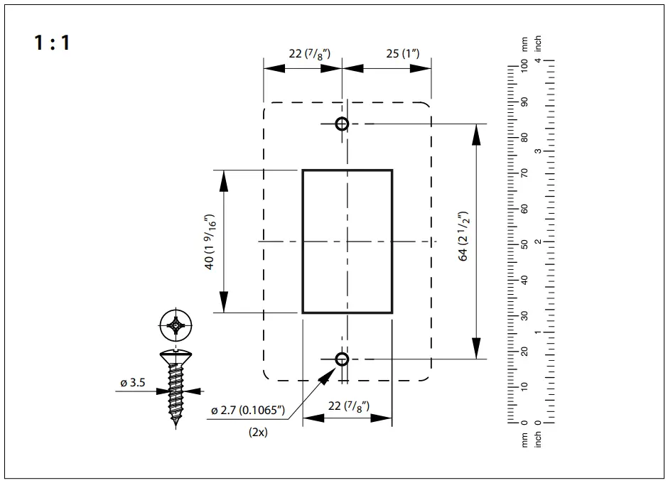
- Bore a hole in the wall for the panel. For the dimensions of this hole, see the drawing under ‘Main Dimensions’, see page 40. Place the panel, with its packing, in the wall.

![]() Note!
Note!
Unpleasant smells caused by fasces will be produced in every blackwater tank. The use of sea water for flushing will increase the smell. The algae in sea water also produce unpleasant smells.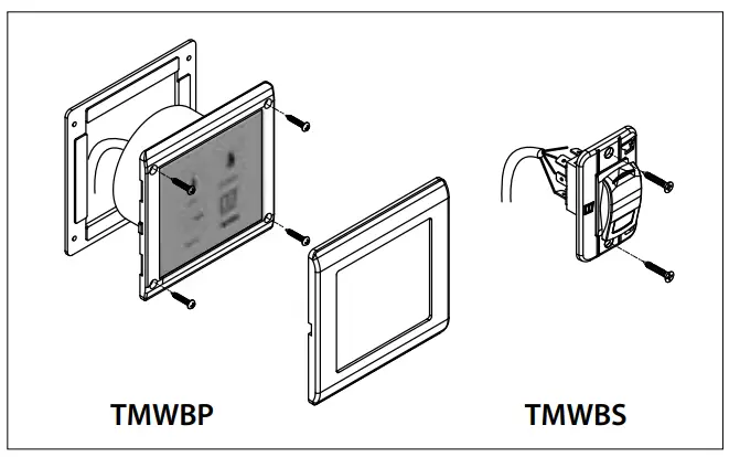
TMWBS:
- Bore a hole in the wall for the switch. For the dimensions of this hole, see the drawing under ‘Main Dimensions’, see page 40. Place the switch in the wall.
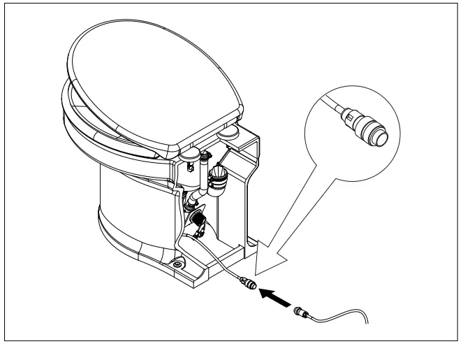
- Feed the cable through the hole into the toilet and connect it tothe toilet’s connection in a dry, protected location.
- Click the finish frame into position over the panel (for TMWBP model only).

Electrical installation
- Check that the voltage given on the type plate on the motor is the same as the voltage on board.
Use batteries with sufficient power to guarantee that the toilet will work correctly. - Connect the power supply as shown in the wiring diagram. Fit a switch and a fuse in the (‘+’) wire. Use wires with minimum cross section of 6 mm2 (AWG10) (for 12 V) or 4 mm2 (AWG12) (for 24 V).
Fitting the toilet to the floor
- Attach the toilet using the fasteners supplied.
![]() WARNING
WARNING
Do not overtighten.
Testing
- Switch on the main switch.
- Open the ball valve in the water supply pipe completely so that there will be a sufficient supply of water for flushing.
- Do not forget to open the shut-off valve in the outlet (if present).
TMWBP | |
|  |
| |
| |
TMWBP | |
|  |
|  |
|  |
| |
Use
- Switch on the main switch.
- Open the ball valve in the water supply pipe completely so that there will be a sufficient supply of water for flushing. Do not forget to open the shut-off valve in the outlet (if present).
TMWBP
A short or long flush can be used.
Explanation:
The particular cycle chosen is carried out automatically after operating the appropriate button.
This cycle consists of:
– A flushing phase:
The magnetic valve allows a quantity of water to flow through for a specified time. This water flows into the toilet bowl.
– A pumping phase:
The motor drives the pump blades. The faeces and toilet paper are now ground up and pumped out.
The ‘ECO’ cycle takes about 10 seconds and the ‘NORMAL’ cycle lasts about 20 seconds.
|  |
| |
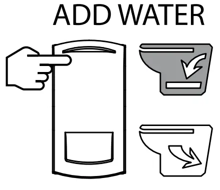
| When the switch (WATER IN) is pressed, the magnetic valve is opened to allow water to run into the toilet bowl |  |
- After using the toilet shut off the ball valve.
- Close the outlet’s shut-off valve
- Switch off the main switch when leaving the ship.
| |
TMWBP | TMWBS |
TMWBS | |
| Flushing: | |
| |
| |
| |
- If the toilet has not been used for some time it is advisable to rinse it with clean water a few times before using it.
The following precautions must be taken during periods of frost (winter) : - Shut off the water supply to the toilet.
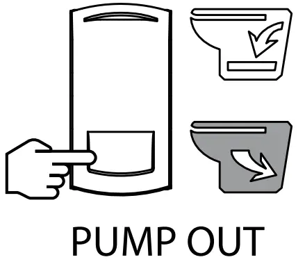
- Pump the toilet empty. (‘EMPTY’ / ‘PUMP OUT’)
- Pour about 2 litres anti-freeze (preferably a biodegradable antifreeze) into the toilet bowl.
- Drain the pipes.
![]() WARNING
WARNING
Anti-freeze can be toxic. Never flush anti-freeze away into the outside water.
Maintenance
Traditional toilet cleaners can be used to clean the toilet and to remove scale.
In order to prevent scale deposits from building up in the pump these must be removed regularly as follows:
- Shut off the water supply by closing the ball valve.
TMWBP | |
|  |
TMWBP | |
| |
- Pour about 1litre of vinegar or scale remover into the toilet bowl and let it soak for some hours.
- Open the ball valve again and carry out several cycles in order to flush the toilet bowl thoroughly and remove all the water used from the pump.
How often the scale needs to be removed depends on the hardness of the water, but it should be done at least twice a year.
Do not use products based on sodium (unblocking products) or solvents. If seawater is used for flushing the toilet should be rinsed through with fresh water every so often to prevent salt deposits from building up.
Technical details
| Voltage | 12 V 24 V |
| Current | 25 A 15 A |
| Maximum vertical lift in discharge | 3 metres (10 ft) |
| Maximum hose length | 30 metres (100 ft) |
| Pump capacity at discharge height of 3 metres | 36 litres/min @ 12 V (7.9 Imp. gallon/min, 9.5 US gallon/min) 43 litres/min @ 24 V (9.5 Imp. gallon/min, 11.3 US gallon/min) |
| Maximum water temperature | 35˚C (95˚F) |
| Noise level | 61 dBA |
| Protection | IP44 |
| Weight | 18 kg (40 lbs) |
Fault Tracing
![]() Ensure that the power supply is switched off during repairs.
Ensure that the power supply is switched off during repairs.
| Fault | Possible cause | Solution |
| (TMWBP) The motor runs and the cycle operates correctly, But the water is pumped out very slowly, or not at all. | The discharge pipe is blocked. | Descale the discharge pipe. |
| The outlet’s shut-off valve is closed. | Open the shut-off valve. | |
| (TMWBP) The cycle runs correctly but there is a large quantity of water left behind in the toilet after each cycle. | The discharge pipe is blocked. | Descale the discharge pipe. |
| The discharge height is too great. | Modify the installation | |
| TMWBS) The motor runs but the water in the toilet bowl is pumped out too slowly or not at all. | The discharge pipe is blocked. | Descale the discharge pipe. |
| The discharge height is too great | Modify the installation. | |
| The outlet’s shut-off valve is closed. | Open the shut-off valve. | |
| The motor makes a rattling noise. | Hard object hitting the revolving blades | Remove object. |
| The cycle is not carried out when the button or switch is pressed. | There is no power | Check the main switch and fuse |
| There is no connection between the switch and the toilet. | Repair the connection. | |
| The switch is faulty. | Replace the switch. | |
| The cycle starts but water flows too slowly into the bowl. | The magnetic valve filter is blocked. | Clean the filter. |
| Water pressure too low. | Ensure minimum water pressure is 1.5 bar (24 psi). | |
| Cycle starts but no water flows into the bowl. | The water supply stopcock is turned of | Open the stopcock. |
| Faulty magnetic valve. | Replace magnetic valve. | |
| Water pressure too low. | Ensure a minimum water pressure of 1.5 bar (24 psi). |
Installation examples
Water supply
Outlet
1 | Pump |
2 | Filter |
3 | Ball valve |
4 | Air valve |
5 | Water tank |
6 | Waste water tank |
Wiring Diagram
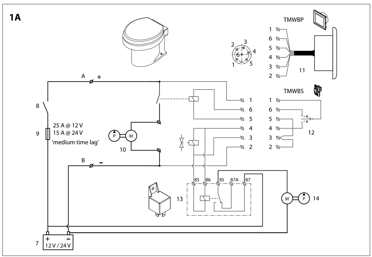
1 | Brown |
2 | Grey |
3 | Yellow |
4 | Green |
5 | Pink |
6 | White |
A | Red |
B | Black |
7 | Battery |
8 | Main switch |
9 | Fuse |
10 | Macerator |
11 | Control panel |
12 | Control switch |
13 | Relay |
14 | Sea water pump |
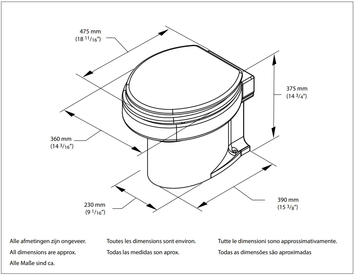
Overall dimensions
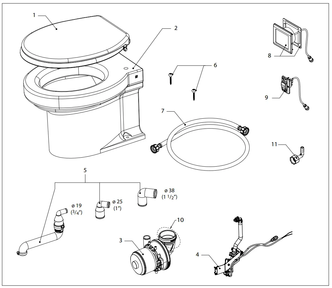
| TMW12Q, TMW24Q | Service parts | ||
pos. | qty | part | description |
1 | 1 | TMWB001 | Toilet seat, soft close, incl. mounting material |
2 | 1 | TMWB002 | Bowl |
3 | 1 | TMWB112 | Macerator, complete 12 V |
1 | TMWB124 | Macerator, complete 24 V | |
4 | 1 | TMW212 | Control unit 12 V |
| TMW224 | Control unit 24 V | ||
5 | 1 | TMWB005 | Discharge tube, incl. duckbill valve and adaptors |
6 | 1 | TMWB008 | Mounting set for bowl |
7 | 1 | TMWB007B | Water supply hose G 3/4 |
8 | 1 | TMWBP | Panel, complete for TM.. toilets |
9 | 1 | TMWBS | Switch for TM.. toilets |
10 | 1 | VP000300 | Inlet elbow |
11 | 1 | PHB13A90 | Bended hose connection 13mm |
Drill pattern
Fokkerstraat 571 – 3125 BD Schiedam – The Netherlands
Tel.: +31 (0)88 4884700 – [email protected] – www.vetus.com