![]() CT4050 Water And Sanitation Cassette Toilets
CT4050 Water And Sanitation Cassette Toilets
Instruction Manual WATER AND SANITATION
CASSETTE TOILETS
CT4050 Water And Sanitation Cassette Toilets
 CT4050, CT4110, CTE4110, CTLP4050, CTLP4110, CTS4050, CTS4110, CTES4110, CTW4050, CTW4110
© 2022 Dometic Group. The visual appearance of the contents of this manual is protected by copyright and design law. The underlying technical design and the products contained herein may be protected by design, patent or be patent pending. The trademarks mentioned in this manual belong to Dometic Sweden AB. All rights are reserved.
CT(E), CTLP, CT(E)S, CTW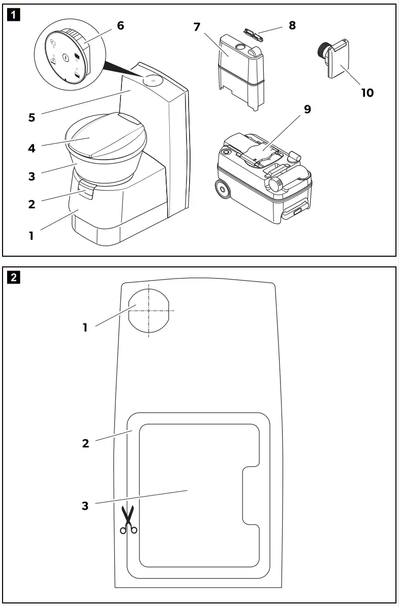
CT(E), CTLP, CT(E)S, CTW
| bl | br | gr | rt | sw | ws |
| Blue | Brown | Grey | Red | Black | White |
Explanation of symbols
Please read these instructions carefully and follow all instructions, guidelines, and warnings included in this product manual in order to ensure that you install, use, and maintain the product properly at all times. These instructions MUST stay with this product.
By using the product, you hereby confirm that you have read all instructions, guidelines, and warnings carefully and that you understand and agree to abide by the terms and conditions as set forth herein. You agree to use this product only for the intended purpose and application and in accordance with the instructions, guidelines, and warnings as set forth in this product manual as well as in accordance with all applicable laws and regulations. A failure to read and follow the instructions and warnings set forth herein may result in an injury to yourself and others, damage to your product or damage to other property in the vicinity. This product manual, including the instructions, guidelines, and warnings, and related documentation, may be subject to changes and updates. For up-to-date product information, please visit documents.dometic.com.
Explanation of symbols![]() WARNING!
WARNING!
Safety instruction: Indicates a hazardous situation that, if not avoided, could result in death or serious injury. CAUTION!
Safety instruction: Indicates a hazardous situation that, if not avoided, could result in minor or moderate injury.![]() NOTICE!
NOTICE!
Indicates a situation that, if not avoided, can result in property damage.![]() NOTE
NOTE
Supplementary information for operating the product.
Safety instructions
The declaration of conformity can be requested from the manufacturer (contact information on the back).
2.1 General safety CAUTION!
- This device can be used by children aged 8 years or above, as well as by persons with diminished physical, sensory or mental capacities or a lack of experience and knowledge, providing they are supervised or have been taught how to use the device safely and are aware of the resulting risks.
- Cleaning and user maintenance must not carried out by unsupervised children.
- Children must be supervised to ensure that they do not play with the device.
- The cassette toilet may be installed only by trained personnel.
![]() NOTICE!
NOTICE!
- All components of the system must be installed in frost-free areas. In freezing temperatures, there is a risk of damage caused by frost.
- Do not use antifreeze. These agents may damage the cassette toilet.
- The operating pressure (water pressure) of the solenoid valve should not exceed 6 bar. The solenoid valve is damaged by excessive pressure.
- The electrical installation must comply with national and local regulations.
In Europe: EN 1645-1, EN 1646-1, EN 1648-1, EN 1648-2
2.2 Installation instructions
The cassette toilet must be installed so that it is accessible for service work, is easy to de-install and install, and can be removed from the vehicle without much effort.
Accessories
Available as accessories (not included in the scope of delivery):
| Designation | Ref. no. |
| Service door SK4 | 9104100197 |
| Service door SK5 | 9104100202 |
Intended use
The cassette toilet is designed for installation and use in recreational vehicles such as motor homes or caravans.
This product is only suitable for the intended purpose and application in accordance with these instructions.
This manual provides information that is necessary for proper installation and/or operation of the product. Poor installation and/or improper operating or maintenance
will result in unsatisfactory performance and a possible failure.
The manufacturer accepts no liability for any injury or damage to the product resulting from:
- Incorrect assembly or connection, including excess voltage
- Incorrect maintenance or use of spare parts other than original spare partsprovided by the manufacturer
- Alterations to the product without express permission from the manufacturer
- Use for purposes other than those described in this manual Dometic reserves the right to change product appearance and product specifications.
Technical description
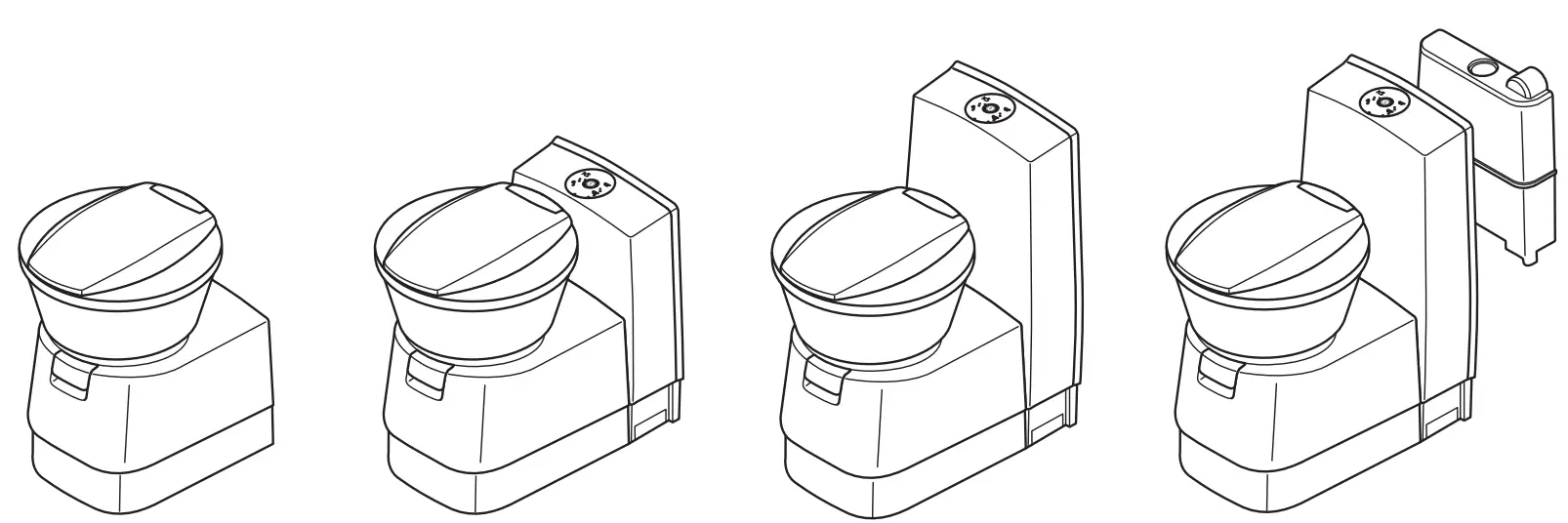
The cassette toilet consists of a toilet permanently installed in the vehicle and a removable, mobile cassette as a holding tank. The cassette is externally accessible through a door. Depending on the model, the cassette toilet is supplied with rinse water from the vehicle-side freshwater tank or a tank integrated in the housing. The following model versions of the cassette toilet are available:
- CT4050, CT(E)4110: detached, without water tank, without console
- CTLP4050, CTLP4110: detached, without water tank, low console
- CTS 4050, CT(E)S4110: detached, without water tank, with console
- CTW4050, CTW4110: detached, with water tank in the console
The 4050 models can be installed in a wet room.
5.1 Description of the components
| No. in fig. 1, page 3 | Designation |
| 1 | Housing for cassette tank |
| 2 | Draining slider for toilet bowl |
| 3 | Toilet bowl |
| 4 | Lid and seat, rotatable |
| 5 | Console |
| 6 | Control and operating panel |
| 7 | Freshwater tank (optional) |
| 8 | CTLP4xxx, CT(E)S4xxx, CTW4xxx only: Wall bracket |
| 9 | Cassette tank (capacity 19 l) |
| 10 | CTW4xxx only: Tank flap (lockable tank flap optional) |
Installing the cassette toilet
6.1 Installing the service door (accessories)
Model-dependent installation instructions are included with the service door (Dometic SK4, SK5).![]() NOTE
NOTE
Prepare the feed-through for the vent hose at the desired location (chapter “Venting the cartridge tank (if a service door is installed only)” on page 28).
6.2 Making wall cutouts
- If a service door is installed: Follow the instructions of the installation manual that comes with the service door.
- Select the model-dependent template and place it on the outside of the vehicle.
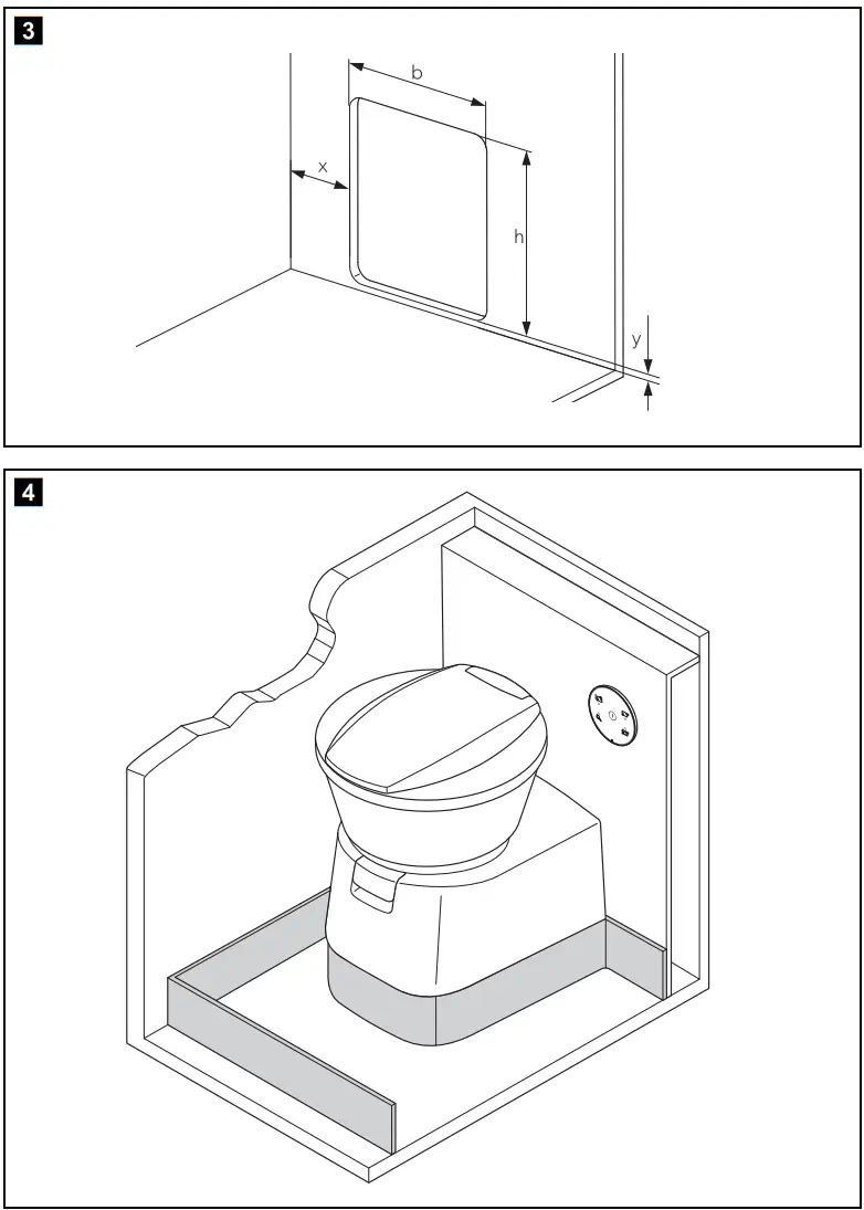
The sample template (fig. 2, page 3) greatly reduced in size shows the tank flap (1), the service door (2) and the filling for the service door (3). - Make a rectangular opening in the outer wall with the following dimensions (fig. 3, page 4):
If a service door is installed only: Wall cut out for the service door
Service door wall cutout SK4:
–y = 25mm
– b = 305 mm ± 1 mm
–h = 375mm ± 1mm
The dimension x results from the placement of the cassette toilet.
Service door wall cutout SK5:
–ymin = 12.5 mm, ymax = 28 mm
– b = 310 mm ± 1 mm
– h = 360 mm ± 1 mm
The dimension x results from the placement of the cassette toilet.
Model CTW4xxx only: Wall cutout for the tank flap
For the CTW4xxx model, mount a tank flap for the integrated water tank.
➤ Note the instructions in chapter “Installing the tank flap” on page 28.
6.3 Setting up the cassette toilet![]() NOTICE!
NOTICE!
All components of the system must be installed in frost-free areas. In freezing temperatures, there is a risk of damage caused by frost.![]() NOTE
NOTE
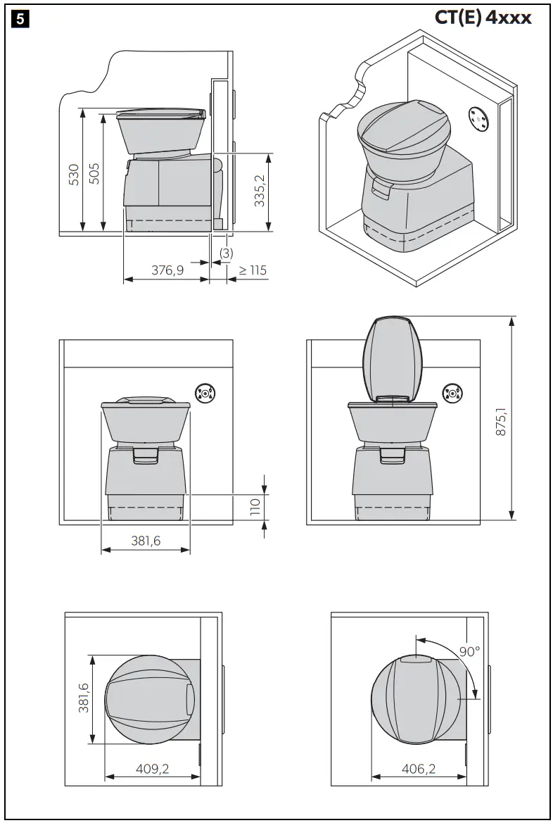
- When installing the cassette toilet in a wet room, the manufacturer recommends that you connect the cassette toilet to the shower tray.
- The cassette toilet base is equipped with a protruding collar for receiving the upper edge of the shower tray (fig. 4, page 4).
- Install the cassette toilet according to the description for the respective model version.
- Set up the cassette toilet so that it is flush to a vertical wall only.
- Leave enough space so that actuation of the draining slider is not restricted.
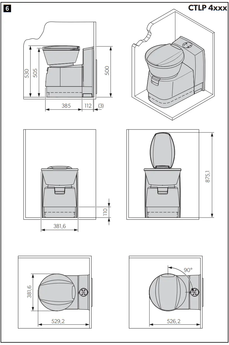
- For the installation, use the dimensional drawings:
– CT4050, CT(E)4110: fig. 5, page 5
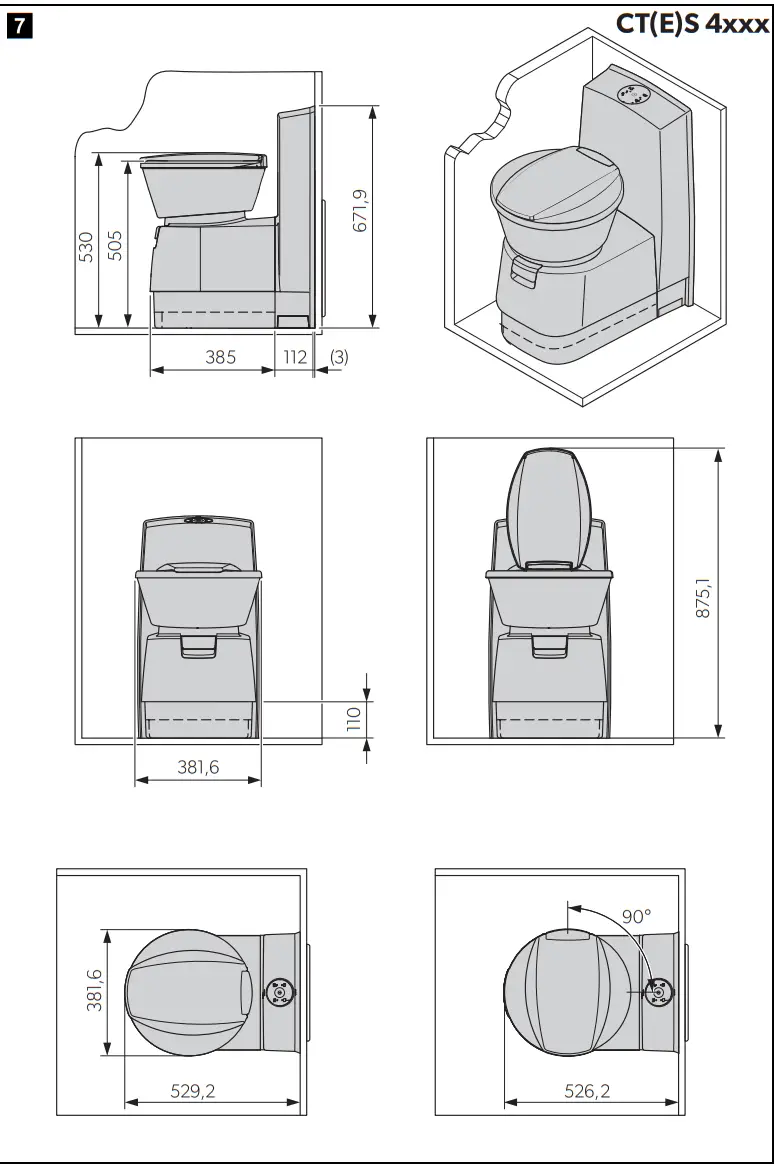
– CTLP4050, CTLP4110: fig. 6, page 6
– CTS 4050, CT(E)S4110: fig. 7, page 7
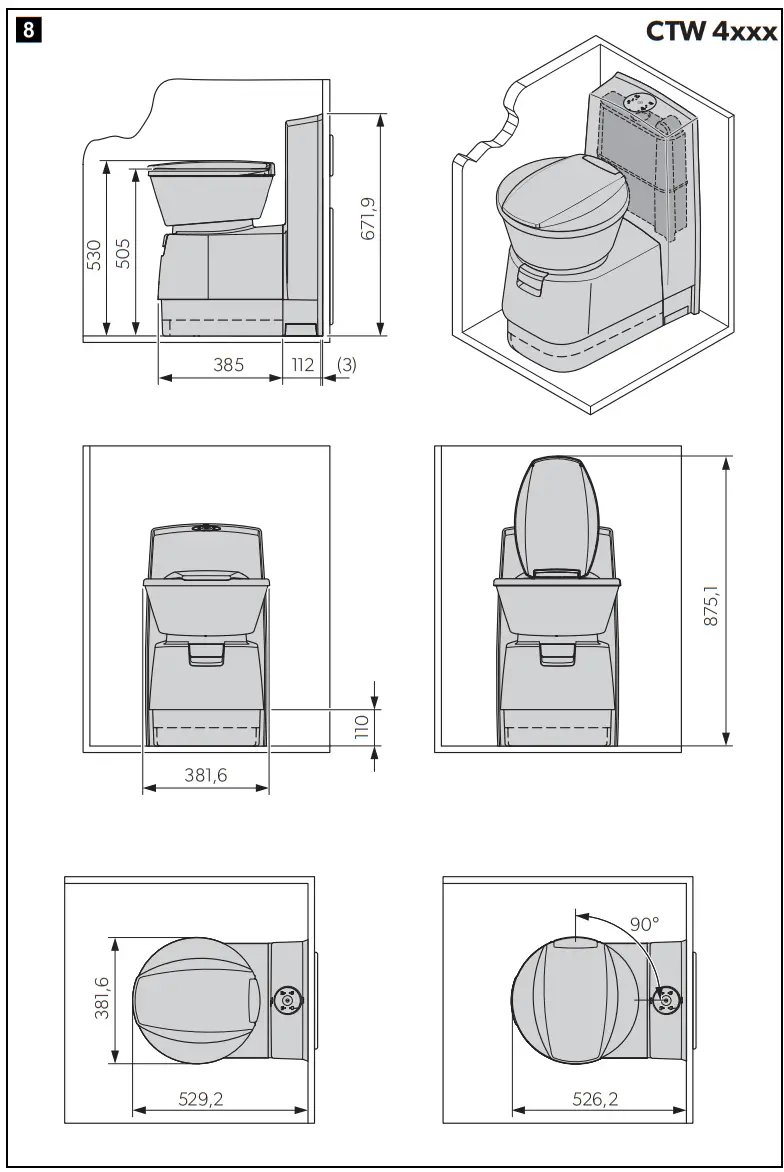
– CTW4050, CTW4110: fig. 8, page 8
6.4 Installing CT(E)4xxx models
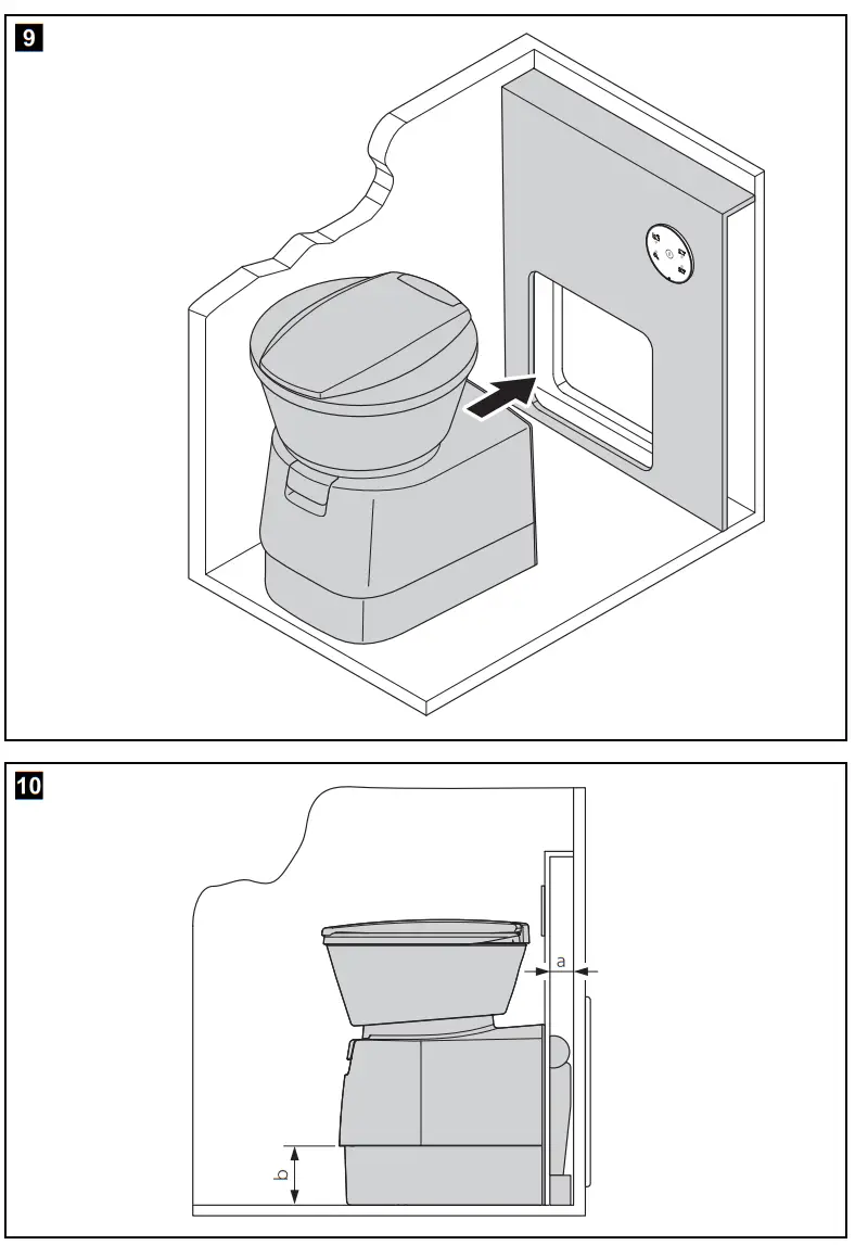
The detached model CT(E)4xxx has no integrated water tank and no console. Set up this model so that the wall behind it can accommodate the control unit of the toilet,
the electrical connections and possibly a water tank. It is best if you put a box in front of the room wall (fig. 9, page 9).
Note here that the cassette protrudes 110 mm out of the cassette housing (fig. 0 a, page 9). The base height is between 50 and 110 mm, depending on model (fig. 0 b, page 9).
- If a service door is installed: Align the cassette toilet according to the service door.
- Place the housing base flush with the installation box so that there is a clean transition and no gap
Attaching cassette toilet CT(E)4xxx
- Place the cassette toilet in the desired position.
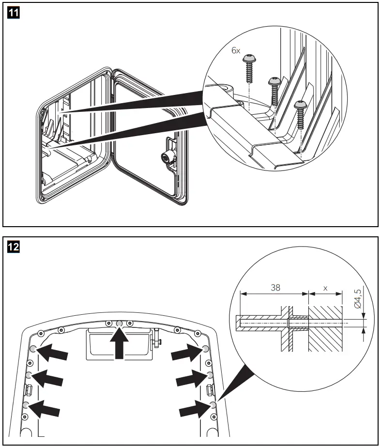
- CT4xxx only: Tightly fasten the base plate with six bolts (4.5 x 45 mm, not included) (fig. a, page 10).
- Bolt the cassette toilet housing to the wall (using a maximum of 7 bolts, not included) (fig. b, page 10).
- CT4110 only: Place the two covers over the fastening screws in the base plate (fig. c, page 11).
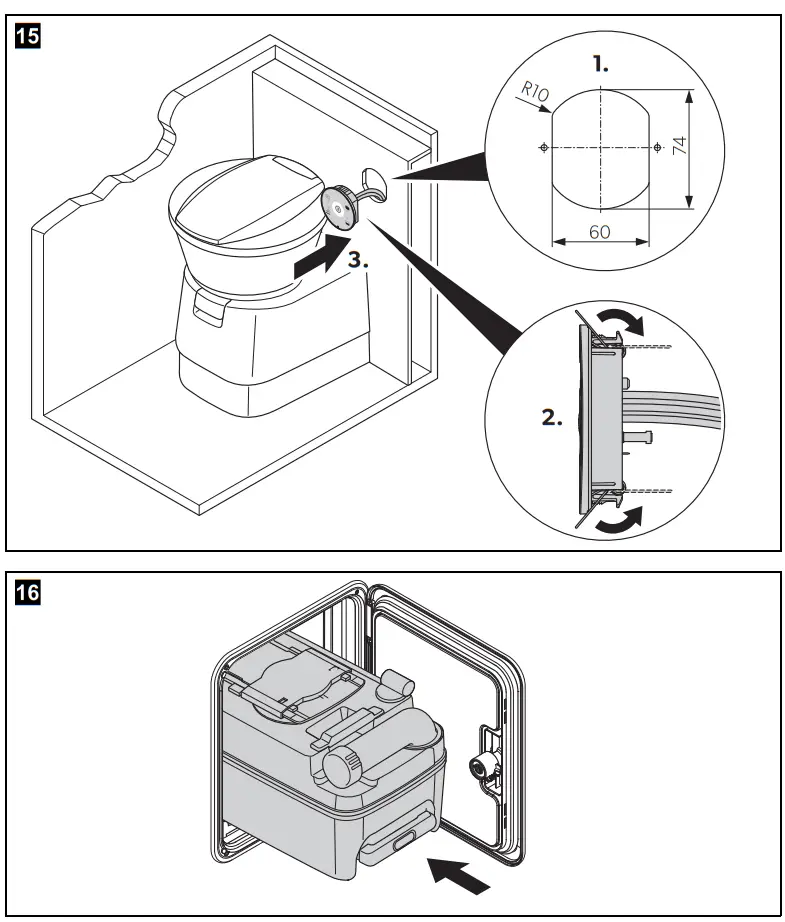
Installing the control and operating panel of the CT(E)4xxx cassette toilet
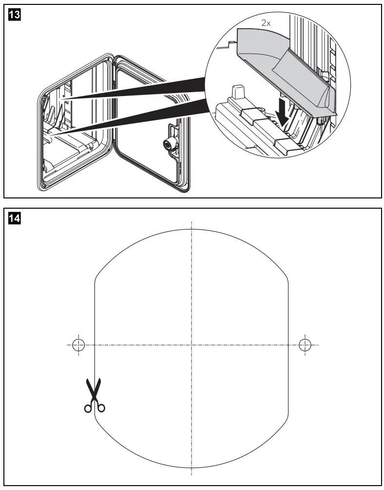
Install the control and operating panel in the wall in the immediate vicinity of the cassette toilet at an easily accessible location.![]() NOTE
NOTE
Use the scale template to make the wall cutout (fig. d, page 11).
- Prepare an opening in the installation box for the control and operating panel (fig. e 1, page 12).
- Connect the electrical cables to the connections of the control and operating panel (chapter “Electrical connection” on page 29).
 CAUTION! There is a risk of injury due to the springs springing back.
 - CT 4xxx only: Press in the retaining springs of the control and operating panel (fig. e 2, page 12).
- Push the control and operating panel into the wall cutout (fig. e 3, page 12).
- Follow the instructions in chapter “Connecting the water supply” on page 27.
- Slide in the mobile tank cassette (fig. f, page 12).
6.5 Installing models CTLP4xxx, CT(E)S4xxx, CTW4xxx
These models have a wall connection console. The control and operating panel is integrated in the wall connection console.
Models CTLP4xxx and CT(E)S4xxx have no water tank, while model CTW4xxx has an integrated water tank.
Setting up cassette toilets CTLP4xxx, CT(E)S4xxx, CTW4xxx
Set up all models with wall connection console directly against the room wall (fig. g, page 13). A previously attached wall bracket is used to secure the cassette toilet and the wall bracket.
- Screw on the wall bracket, level, at the following height (fig. h, page 13):
– CTLP4050, CTLP4110: h = 479.5 mm
– CTS 4050, CT(E)S 4110: h = 651.5 mm
– CTW4050, CTW4110: h = 651.5 mm - Put the entire toilet module into the desired position in front of the wall bracket.
- Lift the cassette toilet and hook the housing into the wall bracket (fig. g, page 13).
- Tightly fasten the base plate with six bolts (fig. a, page 10).
- Slide in the mobile tank cassette (fig. f, page 12).
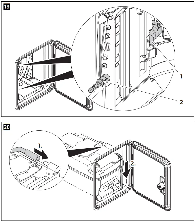
6.6 Connecting the water supply![]() NOTICE!
NOTICE!
- CT4xxx, CTLP4xxx, CTS4xxx, CTW4xxx only: The water supply is connected using a solenoid valve mounted in the toilet housing (fig.19 1, page 14).
- The operating pressure (water pressure) of the solenoid valve should not exceed 6 bar.
- The solenoid valve is damaged by excessive pressure.
![]() NOTE
NOTE
For the CTW4xxx models with an integrated water tank, the water connection is installed at the factory.
- Use a spring band hose clamp to attach the freshwater supply hose to the connection socket (fig.19 2, page 14).
- Perform a leak test.
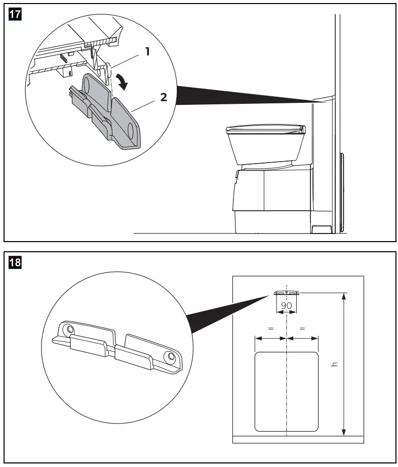
6.7 Venting the cartridge tank (if a service door is installed only)
Service door SK4 and SK5
- In the niche floor, create an opening with a diameter of approx. 12 mm (fig.20, page 14).
- Run the vent hose into this opening for discharge to the outside.
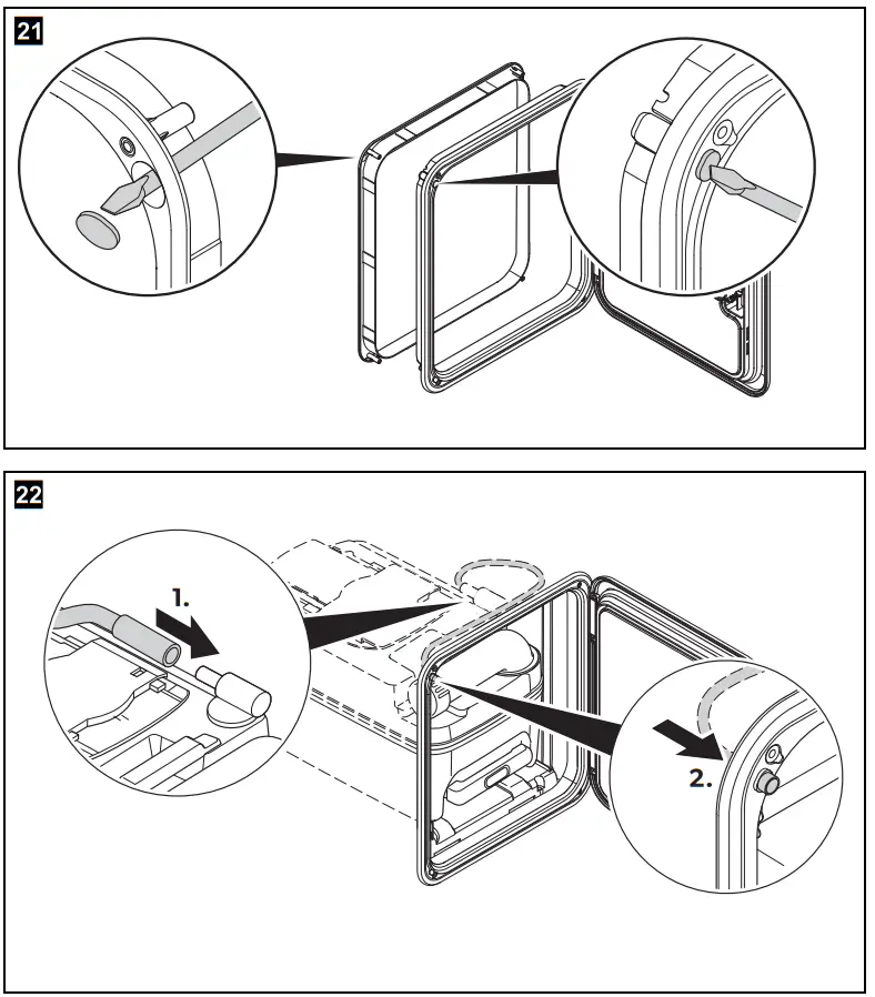
Service door SK5 (optional)
- Press the spray paint out of the inner frame of the door (fig. k, page 15).
- Install the door.
- Insert the hose of the vent into the integrated vent opening of the service door and the cassette tank (fig. 22, page 15).
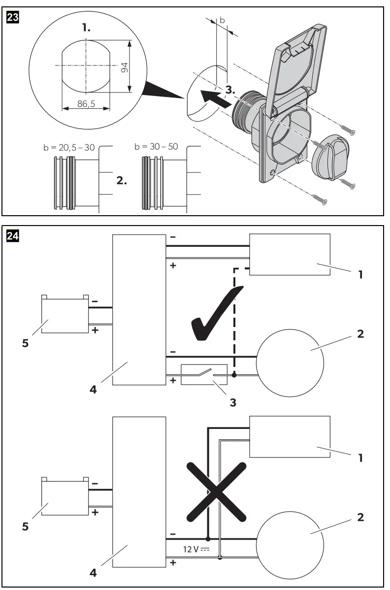
6.8 Instaling the tank flap
For the CTW4xxx model, mount a tank flap for the integrated water tank.
Proceed as follows (fig. 23, page 16):
- Using the template, create an opening in the outer wall.
- Slide the O-ring onto the inner tube of the tank flap.
- Grease the O-ring. This makes it easier for the filler neck to be connected with the upper part of the tank.
- Seal the tank flap watertight (with butyl rubber, for example).
- Tightly fasten the tank flap with four C4x25 countersunk screws (not included).
- Perform a leak test.
Electrical connection
![]() WARNING!
WARNING!
Have the electrical connection carried out by an electrician.![]() NOTICE!
NOTICE!
- Do not connect the cassette toilet to the voltage supply directly in parallel with other power-consuming devices.
- Do not connect the control of the cassette toilet to a pressurized water pump.
- The rated capacity of an external water pump should not exceed 60 W.
![]() NOTE
NOTE
- The external water pump is not included in the scope of delivery.
- A pre-fuse is not necessary, because the cassette toilet is internally fused.
7.1 Models CT(E)4xxx, CTLP4xxx, CT(E)S4xxx with external water pump![]() NOTICE!
NOTICE!
- The rated capacity of an external water pump should not exceed 60 W.
- The 12 V connection cable must have a cross-section of at least ² 1.5 mm .
- A 7.5 A automotive fuse is integrated in the toilet control.
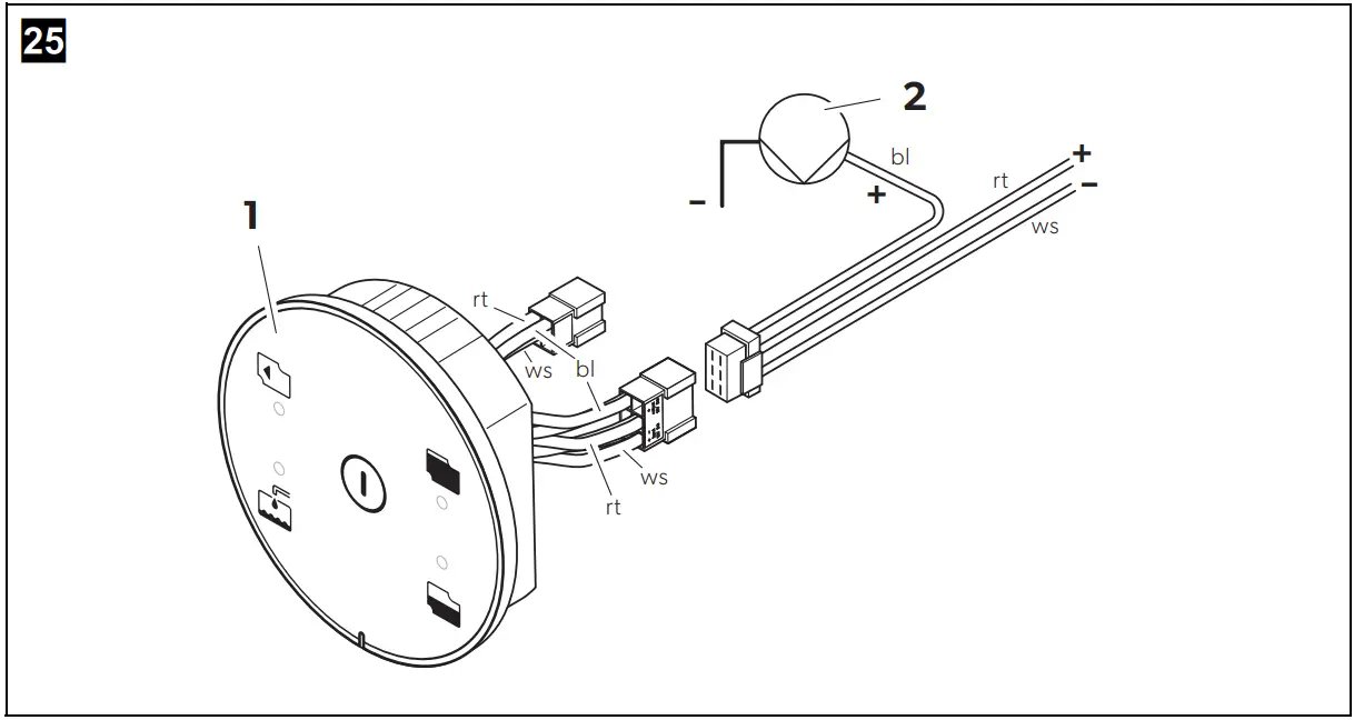
- Connect the cassette toilet via the main terminal block of the vehicle to its own power supply (fig. 24, page 16).
- Connect the external water pump (fig.25, page 17).
Key for fig. 24, page 16:
| No. | Designation |
| 1 | Control and operating panel of the cassette toilet |
| 2 | Water pump (note: not a pressurized water pump) |
| 3 | Switch |
| 4 | Fuse/main terminal box |
| 5 | 12 Vg supply |
System schema of the control and operating panel plug assignment (fig. 25, page 17):
| No. | Designation |
| 1 | Control and operating panel |
| 2 | Water pump |
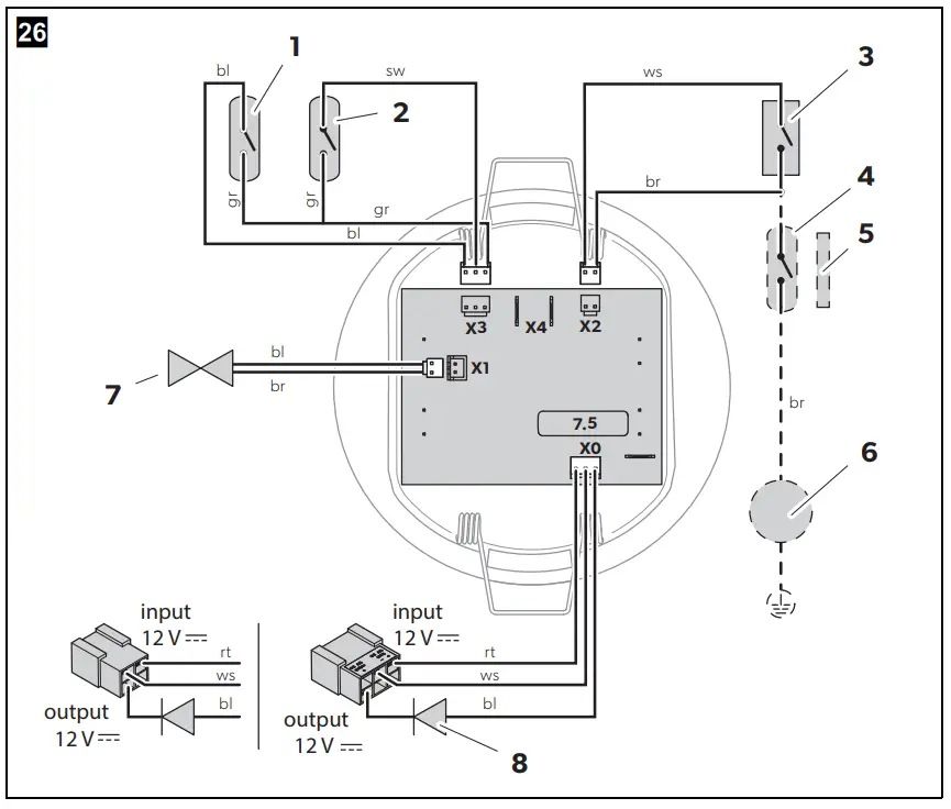
Wiring diagram for external water tank (fig. 26, page 18):
| No. | Designation |
| 1 | Reed switch: Tank status 3/4 full |
| 2 | Reed switch: Tank status 1/1 full |
| 3 | Micro-switch: Position of cassette tank |
| 4 | With SOG® only: Reed switch for SOG® control |
| 5 | With SOG® only: SOG® control solenoid in the slide opening handle |
| 6 | With SOG® only: SOG® fan |
| 7 | Solenoid valve control |
| 8 | Silicon power diode 5 A / 50 V |
7.2 Model CTW4xxx with integrated water pump![]() NOTICE!
NOTICE!
- The 12Vg connection cable must have a cross-section of at least 0.75 mm ² .
- The current consumption of the pump should not exceed 2 A.
- A 7.5 A automotive fuse is integrated in the toilet control.
- Connect the cassette toilet via the main terminal block of the vehicle to its own power supply.
- Make the plug connections between control and operating panel and the cassette tank.
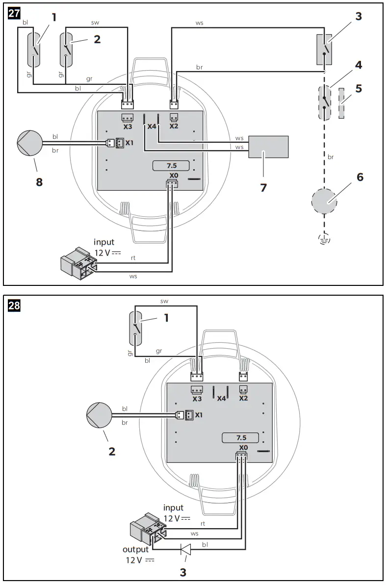
Circuit diagram for integrated water tank and water pump (fig.27, page 19):
| No. | Designation |
| 1 | Reed switch: Tank status 3/4 full |
| 2 | Reed switch: Tank status 1/1 full |
| 3 | Micro-switch: Position of cassette tank |
| 4 | With SOG® only: Reed switch for SOG® control |
| 5 | With SOG® only: SOG® control solenoid in the slide opening handle |
| 6 | With SOG® only: SOG® fan |
| 7 | Reed switch: Freshwater indicator |
| 8 | Internal water pump |
7.3 Model CTE4110
Wiring diagram (fig. 28, page 19):
| No. | Designation |
| 1 | Reed switch: Tank status 1/1 full |
| 2 | Solenoid valve control |
| 3 | Silicon power diode 5 A / 50 V |
Technical data
| Supply voltage | 12 Vg |
| Current consumption | Max. 2 A with internal pump Max. 5 A with external pump |
| Dimensions | See fig. 5, page 5 to fig. 8, page 8 |
| Operating temperature | 0 °C to +50 °C |
| Required pump output | Min. 7 l/min |
| Capacity | 19 l (cassette tank)7 l (freshwater tank, optional) |
| Test mark |
dometic.com
| YOUR LOCAL DEALER dometic.com/dealer | YOUR LOCAL SUPPORT dometic.com/contact | YOUR LOCALSALES OFFICE dometics |
![]() A complete list of Dometic companies, which comprise the Dometic Group, can be found in the public filings of:
A complete list of Dometic companies, which comprise the Dometic Group, can be found in the public filings of:
DOMETIC GROUP AB Hemvarnsgatan 15 SE-17154 Solna Sweden


