![]()
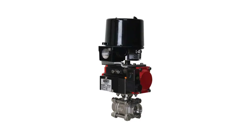
WE05 Series 3-Piece Socket
Weld Stainless Steel Ball Valve
Installation Guide
Series 3-Piece Socket Weld Stainless Steel Ball Valve
The Series WE05 3-Piece Socket Weld Stainless Steel Ball Valve offers the best possible design for socket weld ball valves. The swing-out body feature and seat arrangement allow for trouble-free welding installation. The Series WE05 incorporates a full port 3-piece SS ball valve for ideal flow rates with minimal pressure drop. The valve features a blowout-proof stem for added safety, reinforced PTFE seats and seals for longer life, and a 316 SS (ASTM CF8M) ball for better performance. Actuators are directly mounted creating a compact assembly for tight spaces. Limit switches can be mounted directly to the valves, allowing for remote position indication.
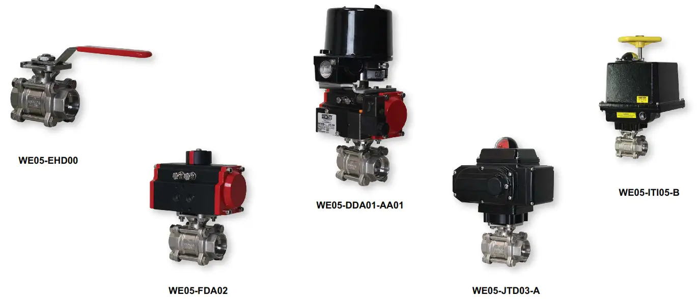
The Series WE05 can be configured with either an electric or pneumatic actuator.
Electric actuators are available in weatherproof or explosion-proof, with a variety of supply voltages and two-position modulating control. Two-position actuators use the supply voltage to drive the valve open or close, while the modulating actuator accepts a 4-20 mA input for valve positioning. Actuators feature thermal overload protection and a permanently lubricated gear train.
The pneumatic double-acting actuator uses an air supply to drive the valve open and closed. The actuator has two supply ports with one driving the valve open and the other driving the valve closed. Spring return pneumatic actuators use the air supply to open the valve and internally loaded springs return the valve to the closed position. Also available is the SV3 solenoid valve to electrically switch the air supply pressure between the air supply ports for opening and closing the valve. Actuators are constructed of anodized and epoxy-coated aluminum for years of corrosion-free service.
SPECIFICATIONS
| VALVE Service: Compatible liquids and gases. Body: 3-Piece. Line Sizes: 1/2 to 3˝. End Connections: Socket weld. Pressure Limits: 20˝ Hg to 1000 psi (-0.7 to 69 bar). Wetted Materials: Body and ball: 316 SS (CF8M); Stem: 316 SS; Seat: RTFE/ PTFE; Seal, Washer, and Packing: PTFE. Temperature Limits: -20 to 392°F (-29 to 200°C). Other Materials: O-ring: Fluoroelastomer; Handle 304 SS; Washer: 301 SS; Stem Nut, Locking Device, Gland Ring: 304 SS; Handle Sleeve: PVC. ACTUATORS Pneumatic “DA” and “SR” Series Type: The DA series is double acting and the SR series is spring return (rack and pinion). Normal Supply Pressure: DA: 40 to 115 psi (2.7 to 7.9 bar); SR: 80 psi (5.5 bar). Maximum Supply Pressure: 120 psi (8.6 bar). Air Connections: DA01: 1/8˝ female NPT; DA02 to DA05: 1/4˝ female NPT; SR02 to SR07: 1/4˝ female NPT. Housing Material: Anodized aluminum body and epoxy-coated aluminum end caps. Temperature Limits: -40 to 176°F (-40 to 80°C). Accessory Mounting: NAMUR standard. | Electric “TD” and “MD” Series Power Requirements: 110 VAC, 220 VAC, 24 VAC, or 24 VDC (MD models not available in 24 VDC). Power Consumption: See page 8. Cycle Time (per 90°): TD01: 4 s; MD01: 10 s; TD02 and MD02: 20 s; TD03 and MD03: 30 s. Duty Rating: 85%. Enclosure Rating: NEMA 4X (IP67). Housing Material: Powder-coated aluminum. Temperature Limits: -22 to 140°F (-30 to 60°C). Electrical Connection: 1/2˝ female NPT. Modulating Input: 4-20 mA. Standard Features: Manual override, position indicator, and TD models come with two limit switches. Electric “TI” and “MI” Series Power Requirements: 110 VAC, 220 VAC, 24 VAC, or 24 VDC. Power Consumption: See page 9. Cycle Time (per 90°): See page 9. Duty Rating: See page 9. Enclosure Rating: NEMA 7. Housing Material: Powder-coated aluminum. Temperature Limits: -40 to 140°F (-40 to 60°C). Electrical Connection: 1/2˝ female NPT. Modulating Input: 4-20 mA. Standard Features: Position indicator and two limit switches. |
| MODEL CHART | ||||||
| Size | Cv (gal/min) | Popular Hand Operated Model | Popular Double Acting Pneumatic Model | Popular Spring Return Pneumatic Model | Popular NEMA 4X Two Position Electric (110 VAC) Model | Popular NEMA 4X Modulating Electric (110 VAC) Model |
| 1/2˝ | 36.64 | WE05-CHD00 | WE05-CDA01 | WE05-CSR02 | WE05-CTD01-A | WE05-CMD01-A |
| 3/4˝ | 67.69 | WE05-DHD00 | WE05-DDA01 | WE05-DSR02 | WE05-DTD01-A | WE05-DMD01-A |
| 1˝ | 110.27 | WE05-EHD00 | WE05-EDA02 | WE05-ESR03 | WE05-ETD01-A | WE05-EMD01-A |
| 1-1/4˝ | 184.73 | WE05-FHD00 | WE05-FDA02 | WE05-FSR03 | WE05-FTD01-A | WE05-FMD01-A |
| 1-1/2˝ | 266.62 | WE05-GHD00 | WE05-GDA03 | WE05-GSR04 | WE05-GTD02-A | WE05-GMD01-A |
| 2˝ | 485.3 | WE05-HHD00 | WE05-HDA03 | WE05-HSR05 | WE05-HTD02-A | WE05-HMD02-A |
| 2-1/2˝ | 791.57 | WE05-IHD00 | WE05-IDA04 | WE05-ISR07 | WE05-ITD03-A | WE05-IMD03-A |
| 3˝ | 1151.95 | WE05-JHD00 | WE05-JDA05 | WE05-JSR07 | WE05-JTD03-A | WE05-JMD03-A |
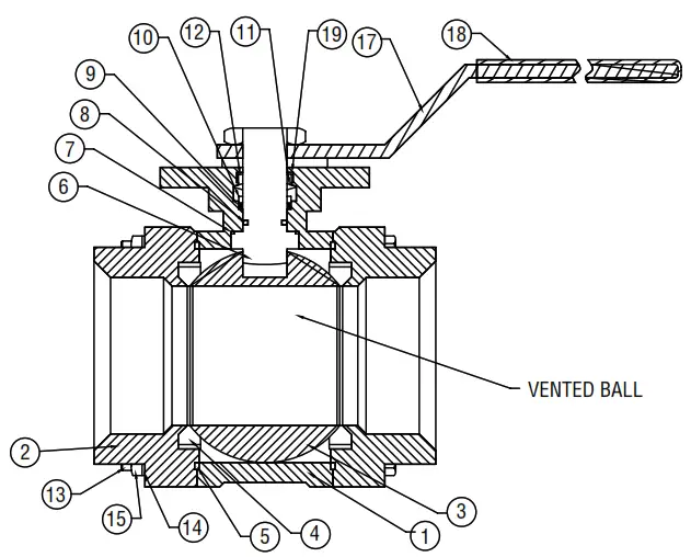
VALVE BILL OF MATERIALS
| Item | Description | Material |
| 1 | Body | ASTM A351-CF8M |
| 2 | Cap | ASTM A351-CF8M |
| 3 | Ball | ASTM A351-CF8M |
| 4 | Ball Seat | PTFE |
| 5 | Joint Gasket | PTFE |
| 6 | Stem | AISI 316 |
| 7 | Thrust Washer | PTFE |
| 8 | Stem Packing | PTFE |
| 9 | High Washer | AISI 304 |
| 10 | Belleville Washer | AISI 304 |
| 11 | Stem Nut | AISI 304 |
| 12 | O-Ring | Fluoroelastomer |
| 13 | Bolt | AISI 304 |
| 14 | Spring Washer | AISI 304 |
| 15 | Hex Nut | AISI 304 |
| 16 | Stopper | AISI 304 |
| 17 | Handle | AISI 304 |
| 18 | Handle Cover | PVC |
| 19 | Lock Washer | AISI 304 |
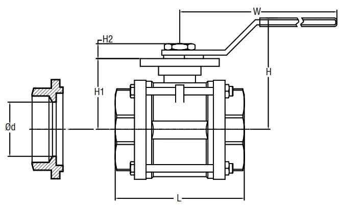
VALVE DIMENSIONAL DRAWING
 | 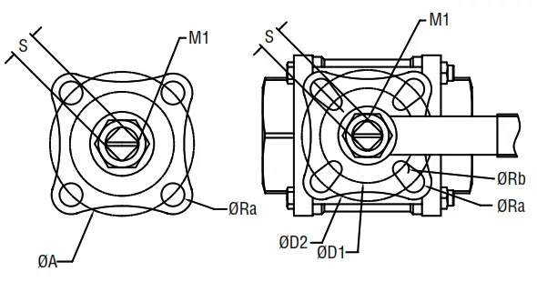 |
| MODEL CHART | |||||||||||||
| Model | Size | Od in (mm) | L in (mm) | H in (mm) | W in (mm) | S in (mm) | ØD1 in (mm) | ØD2 in (mm) | ISO | ØRa in (mm) | ØRb in (mm) | M1 | Cv (gal/min) |
| WE05-CHD00 | 1/2″
| 19/32″ (15) | 2-9/16″(65) | 2-3/8″(60) | 4-3/4″(120) | 23/64″(9) | 1-27/64″(36) | 1/21/32 (42) | F03/F04 | 7/64˝ (2.75) | 7/64˝ (2.75) | M12x1.25 | 37.64 |
| WE05-DHD00 | 3/4″
| 51/64″ (20) | 2-61/64″(75) | 2-17/32″(64) | 4-3/4″(120) | 23/64″(9) | 1-27/64″(36) | 1/21/32 (42) | F03/F04 | 7/64˝ (2.75) | 7/64˝ (2.75) | M12x1.25 | 67.69 |
| WE05-EHD00 | 1″
| 63/64″25) | 3-11/32″(85) | 2-59/64″74) | 5-53/64″(148) | 7/16″(11) | 1-21/32″42) | 1-31/32″(50) | F04/F05 | 9/64˝ (3.5) | 7/64˝ (2.75) | M14x1.5 | 110.27 |
| WE05-FHD00 | 1-1/4″
| 1-17/64″(32) | 3-63/64″(101) | 3-1/8″(79) | 5-53/64″(148) | 7/16″(11) | 1-21/32″(42) | 1-31/32″(50) | F04/F05 | 9/64˝ (3.5) | 7/64˝ (2.75) | M14x1.5 | 184.73 |
| WE05-GHD00 | 1-1/2″
| 1-1/2″(38) | 4-13/32″(112) | 3-3/4″(95) | 7″(178) | 9/16″(14) | 1-31/32″(50) | 2-49/64″(70) | F05/F07 | 3/16˝ (4.5) | 9/64˝ (3.5) | M18x1.5 | 267.62 |
| WE05-HHD00 | 2″
| 2″(50) | 5-1/8″(130) | 4-1/16″(103) | 7″(178) | 9/16″(14) | 1-31/32″(50) | 2-49/64″(70) | F05/F07 | 3/16˝ (4.5) | 9/64˝ (3.5) | M18x1.5 | 485.3 |
| WE05-1HD00 | 2-1/2″
| 2-1/2(63) | 3-3/8″(162) | 4-27/32″(123) | 7″(178) | 3/4″(19) | 2-49/64″(70) | 4-1/64″(102) | F07/F10 | Ø29/64˝ (Ø11) | Ø23/64˝ (Ø9) | M22x1.5 | 792.57 |
| WE05-JHD00 | 3″
| 3″ (76) | 7-13/32″(188) | 5-3/16″(132.) | 7″(178) | 3/4″(19) | 2-49/64″(70) | 4-1/64″(102) | F07/F10 | Ø29/64″(Ø11) | Ø23/64″(Ø9) | M22x1.5 | 1152.95 |
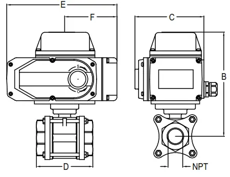
AUTOMATED VALVE DRAWINGS
WITH PNEUMATIC ACTUATOR

| DOUBLE ACTING PNEUMATIC ACTUATOR | |||||||
| 1/2˝ | 3/4˝ | 1˝ | 1-1/4˝ | 1-1/2˝ | 2˝ | 2-1/2˝ | 3˝ |
| 4-5/8˝ | 4-3/4˝ | 5-1/2˝ | 5-3/4˝ | 6-3/4˝ | 7-1/8˝ | 8-3/8˝ | 9˝ |
| 116 mm | 120 mm | 141 mm | 146 mm | 173 mm | 181 mm | 212 mm | 228 mm |
| 2-3/8˝ | 2-3/8˝ | 2-3/4˝ | 2-3/4˝ | 3-1/4˝ | 3-1/4˝ | 3-3/4˝ | 4˝ |
| 61 mm | 61 mm | 71 mm | 71 mm | 82 mm | 82 mm | 94 mm | 101 mm |
| 2-1/2˝ | 3˝ | 3-3/8˝ | 4˝ | 4-3/8˝ | 5-1/8˝ | 6-3/8˝ | 7-3/8˝ |
| 65 mm | 75 mm | 85 mm | 101 mm | 112 mm | 130 mm | 162 mm | 188 mm |
| 4-5/8˝ | 4-5/8˝ | 5-3/4˝ | 5-3/4˝ | 6-5/8˝ | 6-5/8˝ | 7-7/8˝ | 8-1/4˝ |
| 116 mm | 116 mm | 145 mm | 145 mm | 169 mm | 169 mm | 201 mm | 209 mm |
| 1-1/2˝ | 1-1/2˝ | 1-5/8˝ | 1-5/8˝ | 1-3/4˝ | 1-3/4˝ | 2˝ | 2-1/8˝ |
| 37 mm | 37 mm | 41 mm | 41 mm | 46 mm | 46 mm | 52 mm | 55 mm |
| SPRING RETURN PNEUMATIC ACTUATOR | ||||||||
| NPT | 1/2˝ | 3/4˝ | 1˝ | 1-1/4˝ | 1-1/2˝ | 2˝ | 2-1/2˝ | 3˝ |
| B | 5˝ | 5-1/8˝ | 6-1/8˝ | 6-3/8˝ | 7-1/4˝ | 7-7/8˝ | 9-5/8˝ | 10˝ |
| 128 mm | 132 mm | 157 mm | 162 mm | 185 mm | 201 mm | 245 mm | 253 mm | |
| C | 2-3/4˝ | 2-3/4˝ | 3-1/4˝ | 3-1/4˝ | 3-3/4˝ | 4˝ | 4-3/4˝ | 4-3/4˝ |
| 71 mm | 71 mm | 82 mm | 82 mm | 94 mm | 101 mm | 122 mm | 122 mm | |
| D | 2-1/2˝ | 3˝ | 3-3/8˝ | 4˝ | 4-3/8˝ | 5-1/8˝ | 6-3/8˝ | 7-3/8˝ |
| 65 mm | 75 mm | 85 mm | 101 mm | 112 mm | 130 mm | 162 mm | 188 mm | |
| E | 5-3/4˝ | 5-3/4˝ | 6-5/8˝ | 6-5/8˝ | 7-7/8˝ | 8-1/4˝ | 10-7/8˝ | 10-7/8˝ |
| 145 mm | 145 mm | 169 mm | 169 mm | 201 mm | 209 mm | 275 mm | 275 mm | |
| F | 1-5/8˝ | 1-5/8˝ | 1-3/4˝ | 1-3/4˝ | 2˝ | 2-1/8˝ | 2-1/2˝ | 2-1/2˝ |
| 41 mm | 41 mm | 46 mm | 46 mm | 52 mm | 55 mm | 64 mm | 64 mm | |
WITH ELECTRIC ACTUATOR
| ELECTRIC ACTUATOR | ||||||||
| NPT | 1/2˝ | 3/4˝ | 1˝ | 1-1/4˝ | 1-1/2˝ | 2˝ | 2-1/2˝ | 3˝ |
| B | 6-3/8˝ | 6-1/2˝ | 8-3/8˝ | 8-1/2˝ | 8-7/8˝ | 10˝ | 10-3/4˝ | 11˝ |
| 162 mm | 165 mm | 211 mm | 217 mm | 227 mm | 253 mm | 272 mm | 280 mm | |
| C | 5-1/4˝ | 5-1/4˝ | 9-3/8˝ | 9-3/8˝ | 9-3/8˝ | 8-1/2˝ | 8-1/2˝ | 8-1/2˝ |
| 133 mm | 133 mm | 239 mm | 239 mm | 239 mm | 216 mm | 216 mm | 216 mm | |
| D | 2-1/2˝ | 3˝ | 3-3/8˝ | 4˝ | 4-3/8˝ | 5-1/8˝ | 6-3/8˝ | 7-3/8˝ |
| 65 mm | 75 mm | 85 mm | 101 mm | 112 mm | 130 mm | 162 mm | 188 mm | |
| E | 6-1/8˝ | 6-1/8˝ | 8-1/2˝ | 8-1/2˝ | 8-1/2˝ | 8-1/2˝ | 8-1/2˝ | 8-1/2˝ |
| 154 mm | 154 mm | 217 mm | 217 mm | 217 mm | 216 mm | 216 mm | 216 mm | |
| F | 2-3/4˝ | 2-5/8˝ | 5˝ | 5˝ | 5˝ | 5-3/8˝ | 5-3/8˝ | 5-3/8˝ |
| 68 mm | 68 mm | 126 mm | 126 mm | 126 mm | 136 mm | 136 mm | 136 mm | |
WITH EXPLOSION-PROOF ELECTRIC ACTUATOR
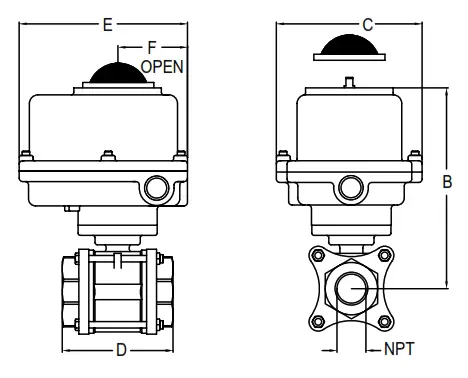
| EXPLOSION-PROOF ELECTRIC ACTUATOR | ||||||||
| NPT | 1/2˝ | 3/4˝ | 1˝ | 1-1/4˝ | 1-1/2˝ | 2˝ | 2-1/2˝ | 3˝ |
| B | 6-5/8˝ | 6-3/4˝ | 7-1/8˝ | 7-3/8˝ | 7-3/4˝ | 8-1/8˝ | 9-7/8˝ | 10-1/8˝ |
| 169 mm | 172 mm | 182 mm | 187 mm | 197 mm | 205 mm | 250 mm | 258 mm | |
| C | 4-1/2˝ | 4-1/2˝ | 4-1/2˝ | 4-1/2˝ | 4-1/2˝ | 4-1/2˝ | 4-3/4˝ | 4-3/4˝ |
| 113 mm | 113 mm | 113 mm | 113 mm | 113 mm | 113 mm | 121 mm | 121 mm | |
| D | 2-1/2˝ | 3˝ | 3-3/8˝ | 4˝ | 4-3/8˝ | 5-1/8˝ | 6-3/8˝ | 7-3/8˝ |
| 65 mm | 75 mm | 85 mm | 101 mm | 112 mm | 130 mm | 162 mm | 188 mm | |
| E | 6-1/4˝ | 6-1/4˝ | 6-1/4˝ | 6-1/4˝ | 6-1/4˝ | 6-1/4˝ | 7-3/4˝ | 7-3/4˝ |
| 160 mm | 160 mm | 160 mm | 160 mm | 160 mm | 160 mm | 196 mm | 196 mm | |
| F | 3˝ | 3˝ | 3˝ | 3˝ | 3˝ | 3˝ | 3-7/8˝ | 3-7/8˝ |
| 77 mm | 77 mm | 77 mm | 77 mm | 77 mm | 77 mm | 98 mm | 98 mm | |
PNEUMATIC ACTUATOR
Note: For optimal operation, pneumatic actuators should be run with a supply of clean, lubricated air.
Spring Return Actuator Operation
![]() WARNING When working on the Actuator/Valve assembly, disconnect the air or power supply to the actuator. Spring return actuators/ valves may change position if power fails or is removed. Never insert any object or body part into the valve body. Severe injury may occur.
WARNING When working on the Actuator/Valve assembly, disconnect the air or power supply to the actuator. Spring return actuators/ valves may change position if power fails or is removed. Never insert any object or body part into the valve body. Severe injury may occur.
Air to PORT 2 (the left-hand port) causes the actuator to turn counterclockwise (CCW). Loss of air to PORT 2 causes air to exhaust and the actuator turns clockwise (CW). This is the FAIL CLOSE operation.
Double Acting Actuators Operation
Air to PORT 2 (the left-hand port) causes the actuator to turn counterclockwise (CCW). Air to PORT 1 (the right-hand port) causes the actuator to turn clockwise (CW).
Pneumatic Actuator Maintenance
Routine maintenance of pneumatic actuator:
- Keep the air supply dry and clean
- Keep the actuator surface clean and free from dust
- Periodic checks should be done to make sure all fittings are tight
- Pneumatic actuators are supplied with lubrication to last the entire life span of the actuator under normal operating conditions.
The outer surface of the pneumatic actuator should be clean to avoid friction or corrosion. All fittings and connections should be tight to prevent leaks during operation. Check the bolts mounting the valve to the actuator to make sure they have not come loose during shipping or installation. Make sure the valve and actuator are not rubbing or jamming against other components during operation.
The actuator should be inspected annually to make sure all fittings and bolts are tight and nothing has come loose during operation.
Disassembling Pneumatic Actuators
![]() WARNING Before beginning disassembly, ensure that the air supply to the actuator has been disconnected, all accessories have been removed, and the actuator has been disassembled from the valve.
WARNING Before beginning disassembly, ensure that the air supply to the actuator has been disconnected, all accessories have been removed, and the actuator has been disassembled from the valve.
- Loosen the end cap fasteners (23) with a wrench (size varies depending on the actuator model). On the spring return actuator, alternate 3 to 5 turns on each fastener until the springs are completely decompressed. Use caution when removing the cap since the springs are under load until the fasteners are fully extended.
- Remove the pinion snap ring (13) with a lock ring tool. The indicator (12) may now be removed.
- Turn the pinion shaft (2) counterclockwise until the pistons are at the full end of travel. Disengage the pistons (15) from the pinion. (Note: Low-pressure air–3 to 5 psi MAXIMUM–might be required to force the pistons completely from the body.) Note the position of the pistons before removing them from the actuator body.
- Remove the pinion through the bottom of the actuator. The actuator is now completely disassembled.
| Failures | Inspection Items | Corrective Action |
| The pneumatic actuator won’t operate | 1. Check the solenoid valve. Is the coil burnt out or is the solenoid spool? 2. The actuator will not move because of debris in the gears. 3. The pneumatic line to the actuator is distorted or smashed. 4. The pneumatic line is frozen because of low temperatures and moisture. | 1. Replace the solenoid valve coil or remove debris. 2. Disassemble the actuator, clean the debris and reassemble the actuator. 3. Replace the pneumatic line with the actuator. 4. Warm the pneumatic lines and remove moisture from the supply lines. |
| Pneumatic actuator runs slowly | 1. The air supply pressure is insufficient. 2. Are other pneumatic devices consuming the air required for the actuator to operate? 3. The pneumatic actuator is undersized for application. | 1. Increase the air supply pressure and look for leaks in the supply pressure pipeline. 2. Increase the air supply or reduce the number of devices operating at the same time. 3. Replace the actuator with a larger actuator. |
Reassembling Pneumatic Actuators
![]() WARNING Be sure the actuator surfaces are free of debris and scratches before reassembling.
WARNING Be sure the actuator surfaces are free of debris and scratches before reassembling.
- Apply a light film of grease to all O-rings and the pinion before replacing.
- Put the pinion (2) back through the actuator with the flats of the pinion shaft running parallel with the body.
- When reassembling the actuator, make sure that the piston racks are square to the actuator body and returned to their original orientation. (Note: The normal operation of all spring return pneumatic actuators is failed CLOSED. To change the orientation to FAIL OPEN, rotate the racks 180º to create a reverse operation.
- When replacing springs in a spring return actuator, ensure that the springs are replaced in their identical position in the end cap from which they were removed.
(Note: In some circumstances, you might want to change the standard 80-pound spring set to fit your application and available air pressure. - Seal the end caps with a petroleum lubricant and bolt them to the actuator body.
- Check the seal of the actuator by covering seal areas (pinion, end caps) with soapy water and using low-pressure air on the actuator to ensure that no bubbles are produced.
Pneumatic Actuators Bill of Materials
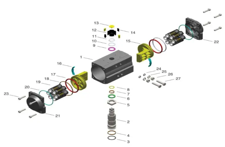
| Part Number | Quantity | Part Name | Material |
| 1 | 1 | Cylinder | Extruded Aluminum Alloy |
| 2 | 1 | Output Shaft | Stainless Steel |
| 3 | 1 | O-ring | Fluorine Silicon Rubber |
| 4 | 1 | Bearing | Nylon46 |
| 5 | 1 | Adjusting Cam | Stainless Steel |
| 6 | 1 | Thrust Bearing | Nylon46 |
| 7 | 1 | Bearing | Nylon46 |
| 8 | 1 | O-ring | Fluorine Silicon Rubber |
| 9 | 1 | Bearing | Nylon46 |
| 10 | 1 | Gasket | Stainless Steel |
| 11 | 1 | Damping Ring | Stainless Steel |
| 12 | 1 | Position Indicator | PPPP+30%GF |
| 13 | 1 | Screw | PPPP+30%GF |
| 14 | 4 | Position Indicating Inserts | PPPP+30%GF |
| 15 | 2 | Piston | Casting Aluminum Alloy |
| 16 | 2 | Guide Ring | Nylon46 |
| 17 | 2 | O-ring | Fluorine Silicon Rubber |
| 18 | 2 | Guide Ring | Fluorine-Carbon Composite Material |
| 19 | 5 to 12 | Spring Assembly | Alloy Spring Steel |
| 20 | 2 | O-ring | Fluorine Silicon Rubber |
| 21 | 1 | Left End Cap | Casting Aluminum Alloy |
| 22 | 1 | Right End Cap | Casting Aluminum Alloy |
| 23 | 8 | End Cap Bolt | Stainless Steel |
| 24 | 2 | O-ring | Fluorine Silicon Rubber |
| 25 | 2 | Gasket | Stainless Steel |
| 26 | 2 | Nut | Stainless Steel |
| 27 | 2 | Adjusting Bolt | Stainless Steel |
| MODEL CHART – DOUBLE-ACTING ACTUATOR TORQUE | |||||||||
|
Model | DA Double-Action Output Torque (lb-in) | ||||||||
| Air Pressure | |||||||||
| 40 psi | 50 psi | 60 psi | 70 psi | 80 psi | 90 psi | 100 psi | 110 psi | 115 psi | |
| ACT-DA01 | 49 | 61 | 74 | 86 | 98 | 110 | 123 | 135 | 142 |
| ACT-DA02 | 104 | 130 | 155 | 181 | 207 | 233 | 259 | 285 | 300 |
| ACT-DA03 | 182 | 228 | 274 | 319 | 365 | 411 | 456 | 502 | 529 |
| ACT-DA04 | 302 | 377 | 453 | 528 | 603 | 679 | 754 | 830 | 875 |
| ACT-DA05 | 396 | 495 | 594 | 693 | 792 | 891 | 990 | 1089 | 1148 |
| ACT-DA06 | 567 | 709 | 851 | 993 | 1135 | 1277 | 1419 | 1561 | 1649 |
| ACT-DA07 | 845 | 1056 | 1267 | 1478 | 1690 | 1901 | 2112 | 2323 | 2450 |
| ACT-DA08 | 1497 | 1871 | 2245 | 2619 | 2993 | 3367 | 3742 | 4116 | 4340 |
| ACT-DA09 | 2253 | 2816 | 3379 | 3942 | 4506 | 5069 | 5632 | 6195 | 6533 |
| MODEL CHART – SPRING RETURN ACTUATOR TORQUE | |||||||||||||||
| Model | Spring Quantity | SR Single Acting Pneumatic Actuator (lb-in) | |||||||||||||
| Air Pressure | |||||||||||||||
| 70 psi | 80 psi | 90 psi | 100 psi | 110 psi | 115 psi | Spring Torque | |||||||||
| 0° Start | 90° End | 0° Start | 90° End | 0° Start | 90° End | 0° Start | 90° End | 0° Start | 90° End | 0° Start | 90° End | 0° Start | 90° End | ||
| ACT-SR02 | 10 | 111 | 86 | 137 | 112 | 163 | 138 | 189 | 164 | 215 | 189 | 231 | 205 | 96 | 70 |
| ACT-SR03 | 10 | 199 | 143 | 245 | 189 | 291 | 235 | 336 | 280 | 382 | 326 | 409 | 353 | 176 | 120 |
| ACT-SR04 | 10 | 348 | 254 | 424 | 330 | 499 | 405 | 575 | 481 | 650 | 556 | 695 | 601 | 274 | 180 |
| ACT-SR05 | 10 | 430 | 312 | 529 | 411 | 628 | 510 | 727 | 609 | 826 | 708 | 885 | 767 | 381 | 263 |
| ACT-SR06 | 10 | 608 | 458 | 750 | 599 | 891 | 741 | 1033 | 883 | 1175 | 1025 | 1260 | 1110 | 536 | 386 |
| ACT-SR07 | 10 | 783 | 663 | 994 | 874 | 1206 | 1085 | 1417 | 1297 | 1628 | 1508 | 1755 | 1635 | 817 | 696 |
| ACT-SR08 | 10 | 1682 | 1208 | 2056 | 1583 | 2430 | 1957 | 2804 | 2331 | 3178 | 2705 | 3403 | 2930 | 1416 | 938 |
| ACT-SR09 | 10 | 2303 | 1483 | 2866 | 2046 | 3429 | 2609 | 3992 | 3173 | 4556 | 3736 | 4894 | 4074 | 2363 | 1575 |
| ACT-SR10 | 10 | 3479 | 2274 | 4337 | 3133 | 5195 | 3991 | 6053 | 4849 | 6911 | 5707 | 7426 | 6222 | 3549 | 2407 |
ELECTRIC ACTUATORS
Electric Installation
- Operate the valve manually and place it in the open position.
- Remove any mechanical stops the valve might have. (DO NOT REMOVE ANY PARTS NECESSARY FOR THE PROPER OPERATION OF THE VALVE, SUCH
AS THE PACKING GLAND, PACKING NUT, ETC.) - Ensure that the actuator output shaft and valve stem are aligned properly. If they are not, operate the valve manually until they are correct.
- Remove the actuator cover.
- Bring power to the actuator. CAUTION: Make sure power is OFF at the main box.
- Wire the actuator per the diagram attached to the inside of the cover. Special actuators (those with positioner boards, etc.) will have diagrams enclosed inside the cover.
- Securely tighten bolts used to mount the actuator to a mounting bracket or directly to the valve mounting pad if it is ISO5211 compliant.
- Cycle the unit several times and check the open and closed positions of the valve. Cams are pre-adjusted at the factory; due to the variety of valve designs and types, however, slight adjustments might be required.
- Replace the cover and tighten the screws.
To Set The Open Position
- Cycle the valve to the open position by applying power to the terminals. The top cam and switch control this position. In the open position, the set screw in the top cam will be accessible.
- If the valve is not open completely:
A. Slightly loosen the set screw on the top cam.
B. Rotate the cam clockwise (CW) by hand until the switch makes contact.
Contact is made when a slight click can be heard. By making incremental CW movements of the top cam, the valve can be positioned precisely in the desired position.
C. When the top cam is set, tighten the set screw securely. - If the valve opens too far:
A. Apply power to terminals. This will begin to rotate valve CW. When the valve is fully open and in the exact position desired, remove power from the actuator.
B. Loosen the set screw in the top cam.
C. Rotate the top cam counterclockwise (CCW) until the switch arm drops off the round portion of the cam onto the flat section. A slight click can be heard as the switch changes state.
D. Continue applying power to terminals until the valve is in the desired position.
To Set The Closed Position
- Apply power to terminals to move the valve toward the closed position. The bottom cam and switch control the closed position. In the closed position, the set screw in the bottom cam will be accessible.
- If the valve is not closed completely:
A. Slightly loosen the set screw on the bottom cam.
B. Rotate the cam counterclockwise (CCW) by hand until the switch makes contact. Contact is made when a slight click can be heard. By making incremental CCW movements of the bottom cam, the valve can be positioned precisely in the desired position.
C. When the top cam is set, tighten the set screw securely. - If the valve closes too far:
A. Apply power to terminals. This will begin to rotate valve CCW. When the valve is fully closed and in the exact position desired, remove power from the actuator.
B. Loosen the set screw in the top cam.
C. Rotate the top cam clockwise (CW) until the switch arm drops off the round portion of the cam onto the flat section. A slight click can be heard as the switch is no longer making contact with the round part of the cam.
D. Continue applying power to terminals until the valve is in the desired position.
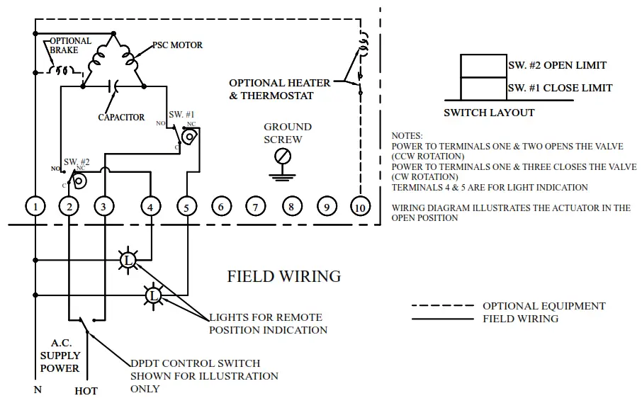
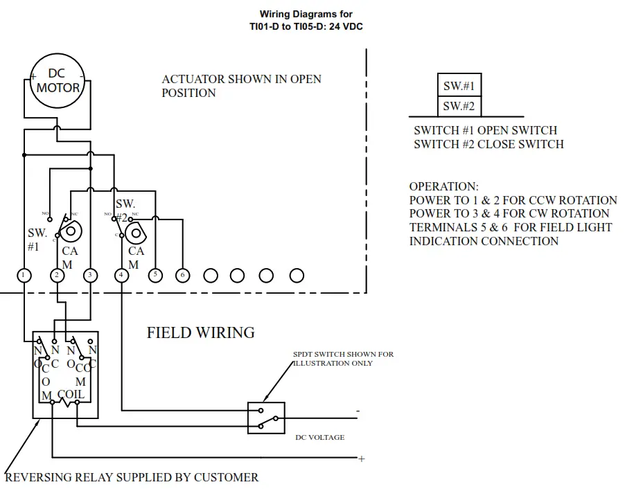
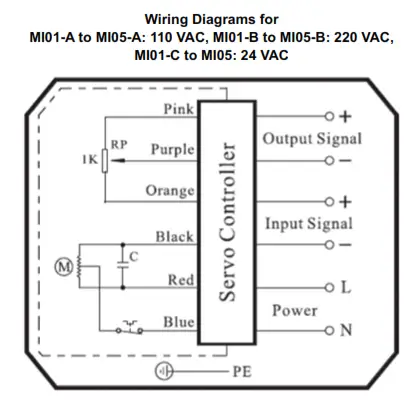
Electric Actuators Wiring Diagram: ACT-TI & ACT-MI
Wiring Diagrams for
TI01-A to TI05-A: 110 VAC, TI01-B to TI05-B: 220VAC, TI01-C to -TI05-C: 24 VAC
Wiring Diagrams for
MD01-A to MD03-A: 110 VAC, MD01-B to MD03-B: 220 VAC, MD01-C to MD03-C: 24 VAC
Wiring Diagrams for
MI01-D to MI05-D: 24 VDC
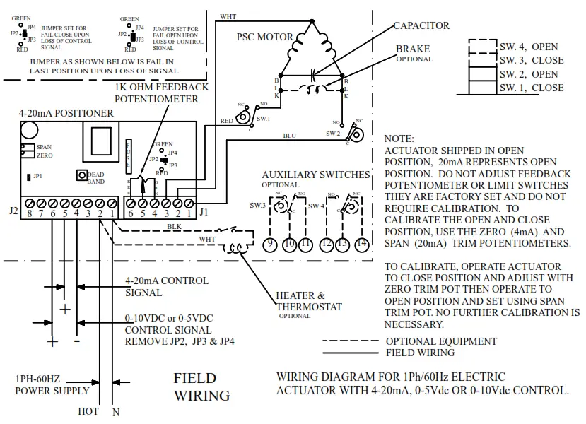
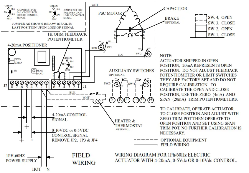
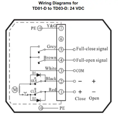
Electric Actuators Wiring Diagram: ACT-TD & ACT-MD
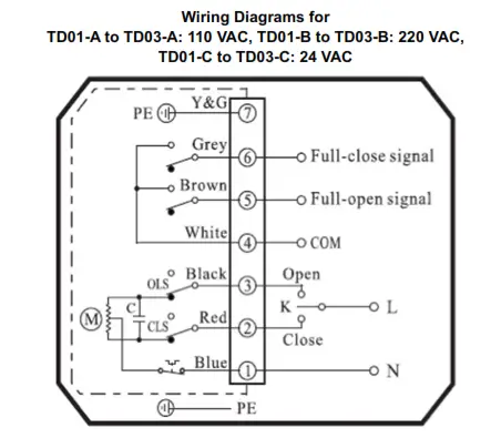 Note: To speed up the installation of the control wires to the ACT-MDXX modulating actuator, it is recommended to remove the control module from the actuator. The control module can be removed by removing the two mounting screws on the left and right of the control module. Install the control wires to the correct terminal points and then reinstall the control module.
Electric Actuator Maintenance
Once the actuator has been properly installed, it requires no maintenance. The gear train has been lubricated and in most cases will never be opened.
Duty Cycle Definition
“Duty Cycle” means the starting frequency.
Formula: Running Time ÷ (Running Time + Rest Time) x 100% = duty cycle
–> Rest Time = Running Time x (1 – duty cycle) ÷ duty cycle
For example, The running time is 15 seconds
30% duty cycle 15 x [(1 – 30%) / 30%] = 35 –> The rest time will be 35 seconds
75% duty cycle 15 x [(1 – 75%) / 75%] = 5 –> The rest time will be 5 seconds
If the duty cycle is higher, the rest time will be shortened, which means the starting frequency will be higher.
Thermal Overload
All actuators are equipped with thermal overload protection to guard the motor against damage due to overheating.
Mechanical Overload
All actuators are designed to withstand stall conditions. It is not recommended to subject the unit to repeated stall conditions.
Explosion-Proof Electric Actuators
![]() WARNING
WARNING
- DO NOT under any circumstances remove the cover of the actuator while in a hazardous location. Removal of the cover while in a hazardous location could cause ignition of hazardous atmospheres.
- DO NOT under any circumstances use an explosion-proof electric actuator in a hazardous location that does not meet the specifications for which the actuator was designed.
- Always verify that all electrical circuits are de-energized before opening the actuator.
- Always mount and cycle test the actuator on the valve in a non-hazardous location.
- When removing the cover, care must be taken not to scratch, scar, or deform the flame path of the cover and base of the actuator, since this will negate the NEMA rating of the enclosure.
- When replacing the cover, take care that the gasket is in place to assure proper clearance after the cover is secured.
- All electrical connections must be in accordance with the specifications for which the unit is being used.
- Should the unit ever require maintenance, remove it from the hazardous location before attempting to work on the unit. If the actuator is in a critical application, it is advisable to have a standby unit in stock.

Electric Actuators Performance Rating
| TD01 | ||||
| Voltage | 110 VAC | 220 VAC | 24 VAC | 24 VDC |
| Cycle Time | 4 s | 4 s | 4 s | 4 s |
| Duty Cycle (Two-Position) | 85% | 85% | 85% | 85% |
| AMP Draw | 0.24 A | 0.16 A | 0.28 A | 1.28 A |
| Torque | 177 in-lb | 177 in-lb | 177 in-lb | 177 in-lb |
| MD01 | |||
| Voltage | 110 VAC | 220 VAC | 24 VAC |
| Cycle Time | 10 s | 10 s | 10 s |
| MD01 Duty Cycle (Modulating) | 85% | 85% | 85% |
| AMP Draw | 0.24 A | 0.16 A | 1.28 A |
| Torque | 265 in-lb | 265 in-lb | 265 in-lb |
| TD02 and MD02 (MD Not Available in 24 VDC) | ||||
| Voltage | 110 VAC | 220 VAC | 24 VAC | 24 VDC |
| Cycle Time | 20 s | 20 s | 20 s | 20 s |
| Duty Cycle (Two-Position) | 85% | 85% | 85% | 85% |
| Duty Cycle (Modulating) | 85% | 85% | 85% | – |
| AMP Draw | 0.24 A | 0.16 A | 1.28 A | 1.28 A |
| Torque | 442 in-lb | 442 in-lb | 442 in-lb | 442 in-lb |
| TD03 and MD03 (MD Not Available in 24 VDC) | ||||
| Voltage | 110 VAC | 220 VAC | 24 VAC | 24 VDC |
| Cycle Time | 30 s | 30 s | 30 s | 30 s |
| Duty Cycle (Two-Position) | 85% | 85% | 85% | 85% |
| Duty Cycle (Modulating) | 85% | 85% | 85% | – |
| AMP Draw | 0.57 A | 0.35 A | 2.03 A | 2.03 A |
| Torque | 885 in-lb | 885 in-lb | 885 in-lb | 885 in-lb |
| TI01 | ||||
| Voltage | 110 VAC | 220 VAC | 24 VAC | 24 VDC |
| Cycle Time | 2.5 s | 2.5 s | 2.5 s | 2.5 s |
| Duty Cycle (Two-Position) | 25% | 25% | 25% | 25% |
| Full Load AMP Draw | 0.64 | 0.32 | 0.4 | 0.4 |
| Torque (in-lb) | 100 | 100 | 100 | 100 |
| TI02 and MI01, MI02 | ||||
| Voltage | 110 VAC | 220 VAC | 24 VAC | 24 VDC |
| Cycle Time (Two-Position) | 5 s | 5 s | 5 s | 5 s |
| Cycle Time (Modulating) | 10 s | 10 s | 5 s | 5 s |
| Duty Cycle (Two-Position) | 25% | 25% | 25% | 25% |
| Duty Cycle (Modulating) | 75% | 75% | 75% | 75% |
| Full Load AMP Draw | 0.38 | 0.18 | 0.7 | 0.7 |
| Torque (in-lb) | 200 | 200 | 200 | 200 |
| TI03 and MI03 | ||||
| Voltage | 110 VAC | 220 VAC | 24 VAC | 24 VDC |
| Cycle Time (Two-Position) | 5 s | 5 s | 5 s | 5 s |
| Cycle Time (Modulating) | 10 s | 10 s | 5 s | 5 s |
| Duty Cycle (Two-Position) | 25% | 25% | 25% | 25% |
| Duty Cycle (Modulating) | 75% | 75% | 75% | 75% |
| Full Load AMP Draw | 0.38 | 0.18 | 0.7 | 0.7 |
| Torque (in-lb) | 300 | 300 | 300 | 300 |
| TI04 and MI04 | ||||
| Voltage | 110 VAC | 220 VAC | 24 VAC | 24 VDC |
| Cycle Time (Two-Position) | 10 s | 10 s | 10 s | 10 s |
| Cycle Time (Modulating) | 20 s | 20 s | 10 s | 10 s |
| Duty Cycle (Two-Position) | 25% | 25% | 25% | 25% |
| Duty Cycle (Modulating) | 75% | 75% | 75% | 75% |
| Full Load AMP Draw | 0.38 | 0.18 | 0.9 | 0.9 |
| Torque (in-lb) | 400 | 400 | 400 | 400 |
| TI05 and MI05 | ||||
| Voltage | 110 VAC | 220 VAC | 24 VAC | 24 VDC |
| Cycle Time (Two-Position) | 15 s | 15 s | 15 s | 15 s |
| Cycle Time (Modulating) | 30 s | 30 s | 15 s | 15 s |
| Duty Cycle (Two-Position) | 25% | 25% | 25% | 25% |
| Duty Cycle (Modulating) | 75% | 75% | 75% | 75% |
| Full Load AMP Draw | 0.38 | 0.18 | 0.7 | 0.7 |
| Torque (in-lb) | 675 | 675 | 675 | 675 |
MAINTENANCE/REPAIR
Upon final installation of the Series WE, only routine maintenance is required. The Series WE is not field serviceable and should be returned if repair is needed. Field repair should not be attempted and may void the warranty.
WARRANTY/RETURN
Refer to “Terms and Conditions of Sale” in our catalog and on our website. Contact customer service to receive a Return Goods Authorization number before shipping the product back for repair. Be sure to include a brief description of the problem plus any additional application notes
NOTES …………………..
©Copyright 2022 Dwyer Instruments, Inc.
DWYER INSTRUMENTS, INC.
P.O. BOX 373 • MICHIGAN CITY, INDIANA 46360, U.S.A.
Phone: 219-879-8000
Fax: 219-872-9057
www.dwyer-inst.com
e-mail: [email protected]
FR# 444257-00 Rev. 5


