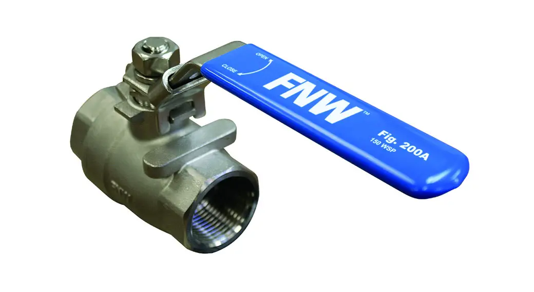
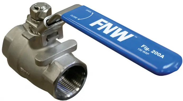
 FIGURE 200A
STAINLESS STEEL BALL VALVES
2 PC FULL PORT 1000 CWP
FEATURES
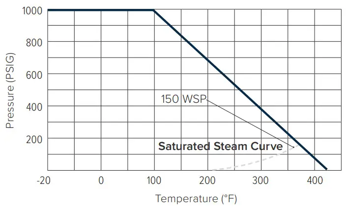
- 1000 PSI CWP non-shock
- 150 PSI WSP
- Threaded NPT ends
- Full port
- Blowout-proof stem
- Adjustable packing
- Investment cast body
- Stainless steel handle
- Locking lever
- RTFE seats
- Vented ball
- Stocked configurations:
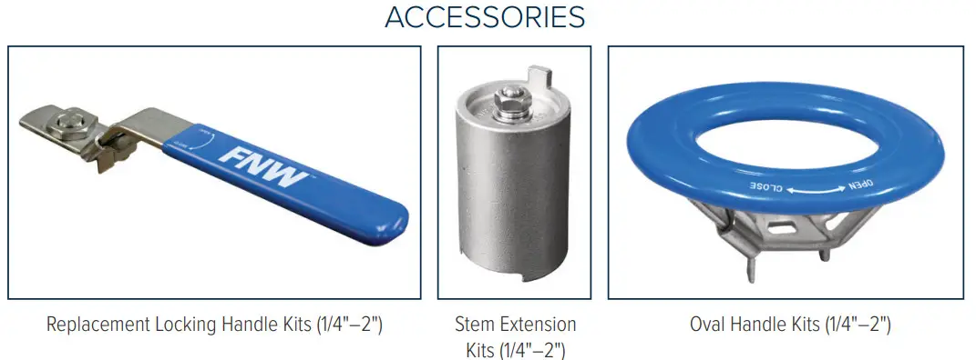
– Standard locking lever (1/4″–2″)
– Oval handle (1/4″–2″) - Manufactured silicone-free
- Replacement locking handle kits are available
- Optional stem extension kit (uses existing valve handle) (1/4″–2″)
- Optional oval handle kit (1/4″–2″)
STANDARDS - Design: MSS SP-110
- End Connections: ASME B1.20.1
- Seat/Shell Test: MSS SP-110
- Corrosion Resistance: NACE MRO103 and MRO175

TORQUE (IN-LBS)
| Size /ΔP | 75 psig | 300 psig | 1000 psig |
| 5 Bar | 20 Bar | 63 Bar | |
| 1/4, 3/8 | 57 | 57 | 57 |
| 1/2 | 57 | 57 | 57 |
| 3/4 | 69 | 69 | 69 |
| 1 | 114 | 126 | 126 |
| 1-1/4 | 150 | 173 | 218 |
| 1-1/2 | 218 | 254 | 299 |
| 2 | 334 | 368 | 437 |
| 2-1/2 | 517 | 564 | 679 |
| 3 | 828 | 932 | 1162 |
| 4 | 1265 | 1404 | 1703 |
For actuator sizing, a safety factor of a minimum of 30% is recommended.
FIGURE NUMBER MATRIX
FNW 200A | |
| Handle Code Standard Handle = Blank Oval Handle = OL | 1/4″ = B 1″ = G 3/8″ = C 1-1/4″ = H 1/2″ = D 1-1/2″ = J 3/4″ = F 2″ = K |
HANDLE KIT CODES (ORDER SEPARATELY)
FNW 310A | |
| Kit Type Locking Handle = LHK Stem Extension = SEK Oval Handle = OH | Size Code 1/4″–1/2″ = BD 3/4″ = F 1″–1-1/4″ = GH 1-1/2″–2″ = JK |
Note: Figure 200A uses the same accessories as the 310A.
CV & WEIGHT
| Size | Cv | Wt (lbs) |
| 1/4 | 15 | 0.73 |
| 3/8 | 15 | 0.68 |
| 1/2 | 18 | 0.75 |
| 3/4 | 36 | 1.14 |
| 1 | 48 | 1.94 |
| 1-1/4 | 93 | 2.82 |
| 1-1/2 | 165 | 4.12 |
| 2 | 207 | 6.48 |
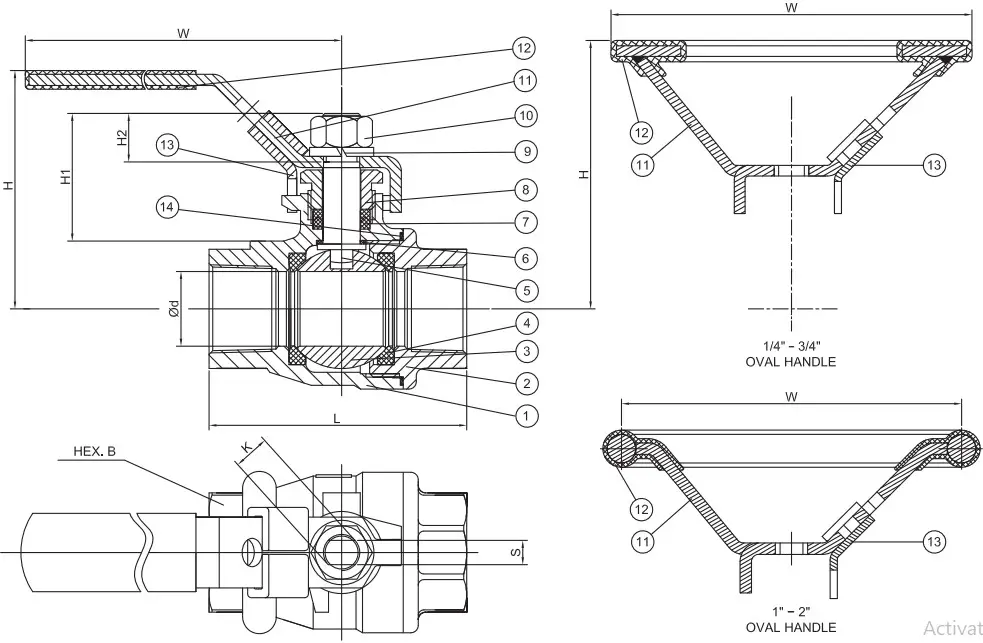
DIMENSIONS (INCHES)
| SIZE | Ød | L | H1 | H2 | Straight Lever | Oval Handle | K (UNC) | S | B | ||
| H | W | H | W | ||||||||
| 1/4 | 0.42 | 2.28 | 1.13 | 0.43 | 2.28 | 3.94 | 2.50 | 3.97 | 5/16-18 | 0.197 | 0.93 |
| 3/8 | 0.47 | 2.28 | 1.13 | 0.43 | 2.28 | 3.94 | 2.50 | 3.97 | 5/16-18 | 0.197 | 0.93 |
| 1/2 | 0.59 | 2.44 | 1.05 | 0.38 | 2.28 | 3.94 | 2.50 | 3.97 | 5/16-18 | 0.197 | 0.98 |
| 3/4 | 0.79 | 2.85 | 1.35 | 0.49 | 2.52 | 5.08 | 2.96 | 520 | 3/8-16 | 0.256 | 1.26 |
| 1 | 0.98 | 3.35 | 1.51 | 0.62 | 3.03 | 6.14 | 3.03 | 520 | 7/16-14 | 0.314 | 1.61 |
| 1-1/4 | 1.26 | 3.70 | 1.46 | 0.55 | 3.27 | 6.14 | 3.22 | 5.20 | 7/16-14 | 0.314 | 1.97 |
| 1-1/2 | 1.50 | 4.13 | 1.96 | 0.89 | 3.78 | 7.19 | 3.80 | 5.63 | 5/8-11 | 0.394 | 2.20 |
| 2 | 1.97 | 4.92 | 1.91 | 0.89 | 4.02 | 7.19 | 4.02 | 5.63 | 5/8-11 | 0.394 | 2.76 |
STANDARD MATERIALS
| Ref. No. | Description | Material | Qty |
| 1 | Body | ASTM A351 Gr. CF8M Stainless | 1 |
| 2 | End Cap | ASTM A351 Gr. CF8M Stainless | 1 |
| 3 | Ball | 316SS Stainless | 1 |
| 4 | Seat | RIFE | 2 |
| 5 | Stem | 316SS Stainless | 1 |
| 6 | Thrust Washer | PTFE | 1 |
| 7 | V-Ring Packing | PTFE | 1 Set |
| 8 | Gland Nut | 304SS Stainless | 1 |
| 9 | Stem Washer | 304SS Stainless | 1 |
| 10 | Stem Nut | ASTM A194-8 Stainless | 1 |
| 11 | Handle | 304SS Stainless | 1 |
| 1″-2 Oval Handle | 3045S+CF8 | 1 | |
| 12 | Handle Sleeve | Vinyl Plastic | 1 |
| 13 | Locking Device | 304SS Stainless | 1 |
| 14 | Body Gasket | PTFE | 1 |
FNW.COM
©2021 Ferguson Enterprises, LLC 0521 2711961
We reserve the right to modify or improve the designs or specifications of our products at any time without notice.


