ASTRALPOOL E Series E25 Saltwater Chlorinator
|
| FOR YOUR SAFETY – This product must be installed and serviced by a trained Swimming Pool Technician in accordance with the latest applicable version of AS/NZS 3000, along with any other applicable local and national installation codes/standards”, and any other local applicable regulations. Before installing this product, read and follow all warning notices and instructions that accompany this product. Failure to follow warning notices and instructions may result in property damage, personal injury, or death. Improper installation and/or operation will void the warranty. Improper installation and/or operation can create unwanted electrical hazard which can cause serious injury, property damage, or death. |
Section 1. Important Safety Instructions
READ AND FOLLOW ALL INSTRUCTIONS
All electrical work must be performed by a qualified installer and conform to all national, state, and local codes. When installing and using this electrical equipment, basic safety precautions should always be followed, including the following:
The E Series Saltwater Chlorinator power supply has an IP23 rating, meaning it is suitable for installation outdoors. For safe operation the power supply must be installed in the correct orientation, with the cables leaving from the bottom of the device. If installing the power supply near the pool or spa water, you must ensure that the rules of AS3136 are followed at all times. AstralPool® strongly recommends that installation be performed by a registered pool builder, electrician or other suitably qualified person |
Risk of electric shock – Install the controller at least 3.5 metres from the inside wall of the pool and/or hot tub using non-metallic plumbing. |
If the supply cord is damaged, it must only be replaced by AstralPool, its service agent or a similarly qualified person, in order to avoid a hazard. |
![]() SAVE THESE INSTRUCTIONS
SAVE THESE INSTRUCTIONS
Section 2. System Overview
Contents
Before starting, check that you have the correct parts as indicated in Table 1. If any parts are missing or incorrect, please call your local distributor or technical support at 1300 186 875 for assistance.
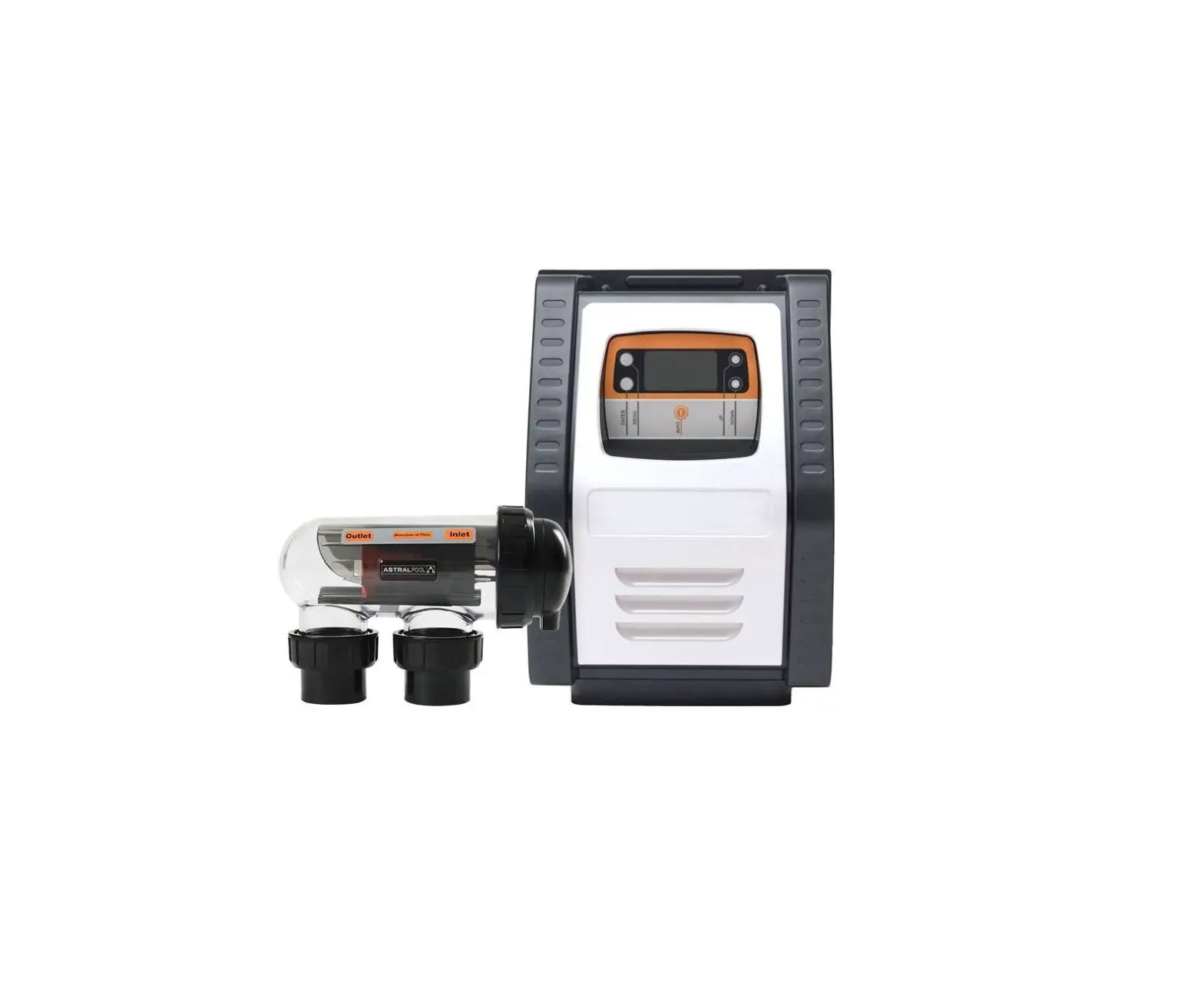
Salt Chlorinator System
E25/E35 Saltwater Chlorinator |
| a. Controller b. Wall Mount Bracket c. Wall Mount Screws Ø7 mm (X2) d. Wall Mount Anchor (X2) e. Electrolytic Cell f. Unions (X2) g. 50mm Glue on Adapter (X2) h. O-ring (X2) |
Table 1. Salt Chlorinator System Contents
Specifications
Salt Chlorinator System
| E 25 | E 35 | |
| Nominal chlorine production | 25 g/h | 35 g/h |
| Nominal output amps | 4.4 A | 5.8 A |
| Required salt level | 6000ppm | |
| Power supply voltage | 230 – 240 VAC | |
| Protection index | IP23 | |
| Flow through the cell | Min. 80 Lpm | |
| Operating water temperature | 10°C – 40°C | |
Table 2. Salt Chlorinator System Specifications
Dimensions
Controller
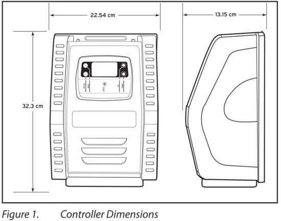
Cell
Materials and Tools
Controller
Tools Needed for Installation |
|
Cell
Tools Needed for Installation |
|
Section 3. Plumbing
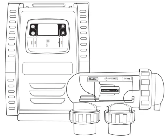
The cell must be plumbed in a position that is accessible for maintenance and within 1.5 meters of the controller. The cell should be the last piece of equipment in the circulation system. The cell must be installed horizontally, level and with correct flow orientation, see Figure 3.
- If you intend to plumb the cell on a bypass, the bypass must be equipped with Isolation valves, see Figure 3.
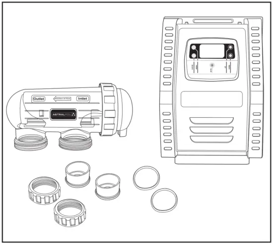
- Plumb the cell inlet and outlet on vertical lengths of 50 mm PVC pipe (if using 40mm pipe, use the provided 40mm reducers). The cell inlet and outlet ports are 11.5 cm apart, see Figure 2. The inlet of the cell is on the side closest to the electrical lead, see Figure 4.
- Put the lock nuts onto the inlet and outlet pipes in the correct orientation, see Figure 4.
- Glue the unions directly onto the pipes.
- Ensure the o-rings are seated properly on the unions.
- Secure the cell to the plumbing by tightening the unions hand tight. DO NOT OVERTIGHTEN.
- Double check cell orientation. The cell inlet is closest to the cell electrical lead.
|
|
Section 4. Install Controller
The controller should be located at or near the equipment pad, at least 3.5 metres or more away from the inside wall of the pool/spa, 1.5 metres off the ground, and within 1.5 meters of the cell. All national, state, and local codes are applicable.
Mount the Bracket
- Determine the controller location.
- Use the enclosed bracket to mark the mounting surface through the screw holes.
- Drill surface with 7 mm bit.
- Install the included wall anchors.
- Hang bracket using the included screws.
- Hang the controller on the wall bracket and slide down to secure in place.

Electrical Connections
FOR YOUR SAFETY: This product must be serviced by a professional pool/spa service technician as described on the front cover of this manual. The procedures in this manual must be followed exactly. Failure to follow warning notices and instructions may result in property damage, serious injury, or death. Improper installation and/or operation will void the warranty. |
The controller must be permanently powered by connection to a 30 mA residential circuit breaker.
A non-replaceable backup power source is incorporated to maintain time-setting memory in the event of a short, infrequent power interruption.
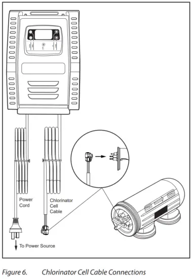
Controller and Chlorinator Cell Wiring
- Connect the Chlorinator Cell Cable to the appropriate ports on the cell.
- Connect the E25/E35 Controller to the power source.

Section 5. Prepare and Balance the Pool
Water Chemistry Table
Test and maintain correct water balance throughout the season, according to the table.
| Free Chlorine | pH | Total Alkalinity (ppm) | Calcium Hard- ness (ppm) | Cyanuric Acid (ppm) | Salt Level (ppm) | Metal | |
| Australian Standard | 1 -3 | 7.2 – 7.8 | 60 – 200 | 100 – 400 *** | up to 50 | 4000 – 7000 | x |
| Ideal range | 1 – 3 | 7.4 | 80 – 140 | 90 – 300 | up to 50 | 4000 at 27°C | < 0.10 ppm |
| To Increase | Add chlorine or increase equip- ment output | Add buffer or soda ash (so- dium carbonate) | Add sodium bicarbonate | Add calcium chloride | Add cyanuric acid | Add salt or minerals ** | x |
| To Decrease | Add muriatic acid | Add muriatic acid or dry acid | Partially drain and refill pool* | Partially drain and refill pool* | Partially drain and refill pool* | Use ‘Metal Remover’ | |
| In Season Testing Frequency | Weekly | Weekly | Weekly | Weekly | Weekly | Monthly | Monthly |
NOTE: Test all equipment sensors quarterly.
* Fill pool with water from the mains water supply. Do not use rain water or well water.
** Do not add salt directly into the skimmer. Do not initiate electrolysis until salt has fully dissolved.
*** Reading is True Calcium Hardness, not Total Hardness.
Table 3.Water Chemistry
Section 6. Operation
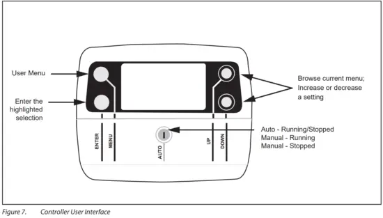
User Interface Overview
Initial start-Up
To avoid risk of serious damage to the equipment, ensure that all salt added to the pool has completely dissolved before activating the chlorination function of your system. |
The following setting must be configured at the initial start up of the device. Settings can be changed or updated at a later time using the general menu, details can be found in Section 7.
Output can be set between levels 1 to 8 (P1 to P8), this is controlled in increments from the “main screen” by pressing UP ![]() or DOWN
or DOWN ![]() . The set value is valid until the next modification.
. The set value is valid until the next modification.
System Power
- Press AUTO to cycle between:
Manual – Running
Manual – Stopped
Auto
Auto – Running indicates that the chlorinator is running within a timer period.
Auto – Stopped indicates that the chlorinator is outside of a timer period.
Set Clock
- Press MENU
 and screen should display CLK. Press ENTER .
 - Press ENTER and the hour digit will flash. Use UP
 or DOWN to adjust.
 - Press ENTER to change to minutes and set. Use UP or DOWN to adjust.
- Press ENTER and select AM or PM. Use UP or DOWN to adjust.
- Press MENU to save.
Section 7. Installing Equipment
Programming/Timers
The controller has an internal operating timer that is used to define the length of time for the filter pump to operate during two separate time periods each day.
In order to complete the timer program, it is necessary to enter and validate both ON and OFF times. If no timer is set, the filtration and / or chlorination will run continuously
The filtration operating times must be sufficient to correctly treat the water.
Example – single speed pump:
In Season filtration time: 8-10 hours per day.
Off Season filtration time: 4-5 hours per day.
Example – variable speed pump (when running at lower speeds):
In Season filtration time: 12-14 hours per day
Off Season filtration time: 8-10 hours per day
Filter Pump Programming
- Press MENU
- Press the MENU again and screen should display TMR. Press ENTER .
- Use UP or DOWN to adjust start time for TIMER 1. Press ENTER .
- Use U P or DOWN to adjust the stop time for TIMER 1. Press ENTER .
- Repeat for TIMER 2.
User Operation Modes
The user mode buttons enable you to select and to automatically or manually control the chlorinator/ pump. Functions are as follows:
a. POOL MODE:
- Auto – Running/Stopped: The chlorinator/pump will run according to how you have set the timers.
- Manual – Running: The chlorinator/pump will run continuously.
- Manual – Stopped: The chlorinator/pump will stay off continuously.
Maximum efficiency will be achieved from your chlorinator at the following levels:
- Water temperature 15 Degrees Salt level required is 6000 ppm.
- Water Temperature 25 Degrees Salt level required is 4,100 ppm.
Section 8. Inspecting and Cleaning the Electrode
In areas that experience calcium hardness the cell electrode will benefit from cleaning.
- Switch off the filter pump and chlorine generator, close necessary valves and unplug the cell terminal cap.
- Unscrew the retaining ring and remove the electrode. If calcium buildup is present, immerse the electrode in cell cleaning solution without immersing the terminals.
- We recommend using Purex Salt Cell Cleaner to clean the electrode. However, you can mix your own by carefully adding one (1) part of Hydrochloric (Muriatic) acid to ten (10) parts water. Stronger solutions will shorten terminal life.
- Allow the cleaning solution to dissolve the calcium deposits for about 10 minutes.
NOTE: Dispose of the cleaning solution at an approved Council Depot and never into storm water or sewage drains. - Rinse the electrode in clean water and re-fit the electrode in the cell housing.
- Replace the cell head and plug assembly.
- Reset valves and switches.
- Turn pump and controller on.
- Confirm chlorine output and settings on the power pack. Timer programs will be automatically retained.
Section 9. Winterizing
The chlorinator has a protective system which will limit sanitizer production during unfavorable operating conditions, such as cold water or lack of salt.
Active winterizing leaves the filter pump and chlorinator running during the winter. This is safe for temperatures above 10°C. If temperatures drop below 10°C, the chlorination cell needs to be deactivated.
Passive winterization calls for the pool to be shut down. Water levels will need to be lowered and the piping will need to be drained. The cell electrode can be left in place with isolation valves open.
Reopening the Pool
Required actions:
- Adjust the water level (too much or too little)
- Check the water parameters.
- TAC/TH/pH/Salinity/Chlorine/Stabilizing Agent/ Copper/Metals.
- Adjust the parameters to obtain a balanced, healthy pool, see Section 5.
- Check the condition of the equipment (pump, filter, chlorinator, electrolytic cell).
- Where necessary, check the sensors, clean if needed and re-calibrate.
- Once the salt level has reached the required level of 6000ppm and has dissolved in the water, restart the salt chlorinator.
Section 10. General Maintenance
If the supply cord is damaged, it must be replaced by AstralPool, its service agent or a similarly qualified person in order to avoid a hazard.
⚠ WARNING Operating the chlorinator with less than 3000 ppm of dissolved salt in the water may cause damage to the cell and will void the warranty. Never start the chlorinator, until the correct quantity of salt has been added and dissolved in your pool water. |
Cell Maintenance
Your E25/E35 Saltwater Chlorinator has an automatic cleaning feature, that under normal conditions, will keep the cell plates clear of deposits of salt and calcium.
The cell has a negative charge sensor that monitors the flow and salt levels of the water. This sensor is designed to be fail safe. As it is negative charge deposits of calcium or other debris that may be deposited on it, causing an indication of low salt or no flow condition.
Should a low salt condition be indicated, have your salt level checked at your local pool shop. If the low salt condition persists, or a no flow condition is indicated when the supply pump is operating, you may need to manually clean your E25/E35 Saltwater Chlorinator Cell. See Section 9 for cleaning instructions.
Maintenance Schedule
The E25/E35 Saltwater Chlorinator has high velocity water with chemicals in it. Some of these parts will wear in the normal course of use and require regular checks and maintenance. Performing these checks and maintenance will identify parts that have worn and require repair/ replacement before further serious damage is sustained. A small amount of regular care and attention to your pool equipment will help ensure long life and trouble free performance.
To protect against extremes of temperature, your unit is vented to allow the electronics to cool. Ants and some insects are often attracted to the warmer, dry environment inside the enclosure. We recommend that, with power turned off, you spray a surface insecticide on the surfaces surrounding the control to prevent ant and insect ingress. Repeat every three months or as necessary.
Note: Regular maintenance is important to ensure long life and trouble free performance of your pool equipment. If unable to perform the maintenance yourself, contact your local pool professional to request assistance with the maintenance.
| Timing | Maintenance Check | Service Action If Required |
| Weekly or sooner | Check Cell for calcium buildup | Soak electrode in mixture of 10 parts water to 1 part acid. Use a soft brush only if required. |
| Check water chemistry | Balance pH in pool and adjust output of unit to ensure satisfactory production of chlorine. | |
| Check cable connections to Cell | Ensure no water contact is occurring with pins. | |
| Every Three Months | Check Cell connections for leaks | Isolate Pump, turn power off, clean and grease O rings or replace if necessary |
| Check for insects/ants | Spray a surface insecticide on the surfaces around the unit to prevent ant and insect ingress | |
| Every Six Months | Check chlorine levels and pump operating hours | Adjust timer and output depending on demand for current season. |
| Prevent insect ingress to controller | Turn controller off, use an insect spray and spray onto walls around controller. Do not spay directly into unit. |
Table 4. E25/E35 Saltwater Chlorinator Maintenance Schedule
Section 11. Troubleshooting
When there is an error condition, “ERROR” flashes on the display along with the error code.
| Fault Indication | Possible Cause | Solution |
| NO FLOW (NO F) |
|
|
| LOW SALT (LO S) |
|
|
| Display Blank |
|
|
| Low/No Chlorine in pool |
|
|
| Clock loses time when main power is removed |
|
|
| Timer is set to OFF in the TMR menu |
|
|
Table 5. Troubleshooting
 | For full warranty terms and conditions and to register your warranty, simply visit www.astralpool.com.au/warranty or www.astralpool.com.nz/warranty and complete your details. Or scan the QR code and be taken directly to the registration page |
 | Record your equipment details here for quick reference: Model No.: ________________________________ Serial No.: ________________________________ |
Fluidra Group Australia
219 Woodpark Road
Smithfield, N.S.W., 2164, Australia
1.300.186.875
www.astralpool.com.au
©2021 Fluidra S.A. All rights reserved. This document is subject to change without notice.