![]()
Quick Reference Guide
Water Source Heat Pump Axiom™
Vertical — Standard Efficiency 0.5 to 5 Tons
GEVG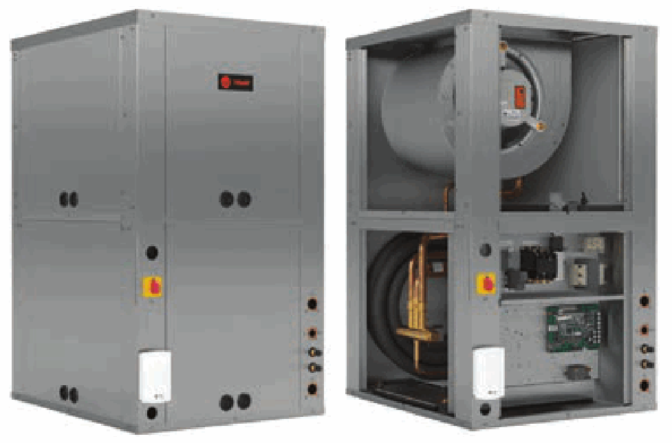
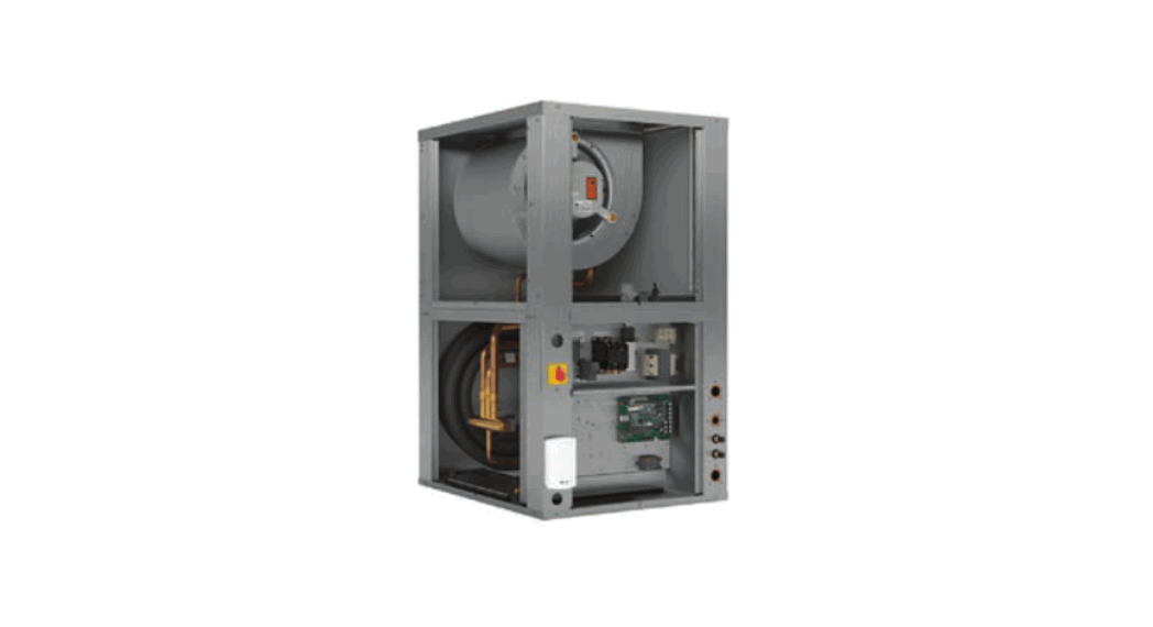
GEVG Water Source Heat Pump
Table 1.List of options
| Factory Installed Options | Field Installed Options |
| 1-inch or 2-inch Ducted Filter Rack | 2-inch or 4-inch Ducted Filter Rack |
| Air-Fi® Wireless Communications | Ducted Panel |
| Deluxe 24V, UC400B or ZN524 Controls | Hose Kits (or ship separate hoses and valves) |
| Factory-mounted Isolation Valve | Pump Module |
| Hot Gas Reheat | Pump Module Hose Kit |
| Low, Medium and High Electric Heat | Thermostats or Zone Sensors |
| Matte or Foil Face Insulation | Waterside Economizer |
| MERV 8 or 13 Filters | |
| Polymer or Stainless Steel IAQ Drain Pan | |
| Recessed Unit Mounted Disconnect Switch | |
| Standard or Deluxe Sound Package |
Table 2.General data – models GEVG006-024
| Model GEVG | 006 | 009 | 012 | 015 | 018 | 024 |
| Unit Size width x depth x height (in.) | 19 x 19 x 30 | 19 x 19 x 30 | 19 x 19 x 30 | 21.5 x 21.5 x 34 | 21.5 x 21.5 x 34 | 21.5 x 23 x 36 |
| Compressor type | Rotary | Rotary | Rotary | Rotary | Rotary | Scroll |
| Net weight (lbs.) | 149 | 149 | 149 | 155 | 157 | 210 |
| Ship weight (lbs.) | 201 | 201 | 201 | 210 | 212 | 268 |
| Filter size nominal (in.) | 14 x 16 | 14 x 16 | 14 x 16 | 16 x 19 | 16 x 19 | 16 x 19 |
| Water in/out size (FPT) | 0.5 | 0.5 | 0.5 | 0.5 | 0.5 | 0.75 |
| Condensate size (NPTI) | 0.75 | 0.75 | 0.75 | 0.75 | 0.75 | 0.75 |
| Blower wheel Size (in.) | 9 x 6 | 9 x 6 | 9 x 6 | 9 x 8 | 9 x 8 | 10 x 8 |
Table 3.General data – models GEVG030-060
| Model GEVG | 030 | 036 | 042 | 048 | 060 |
| Unit Size width x depth x height (in.) | 21.5 x 23 x 36 | 21.5 x 26 x 38 | 21.5 x 26 x 38 | 24 x 32.5 x 42 | 24 x 32.5 x 42 |
| Compressor type | Scroll | Scroll | Scroll | Scroll | Scroll |
| Net weight (lbs.) | 214 | 220 | 252 | 280 | 285 |
| Ship weight (lbs.) | 272 | 280 | 312 | 343 | 348 |
| Filter size nominal (in.) | 16 x 19 | 18 x 23 | 18 x 23 | 20 x 30 | 20 x 30 |
| Water in/out size (FPT) | 0.75 | 0.75 | 0.75 | 1.00 | 1.00 |
| Condensate size (NPTI) | 0.75 | 0.75 | 0.75 | 0.75 | 0.75 |
| Blower wheel Size (in.) | 10 x 8 | 10 x 9 | 10 x 9 | 11 x 11 | 11 x 11 |
Table 4.ANSI/AHRI/ASHRAE/ISO13256-1 WLHP, GWHP and GLHP performance – 0.5 to 5 Tons
| Model | Rated GPM | Rated CFM | Water Loop Heat Pump | Ground Water Heat Pump | Ground Loop Heat Pump | |||||||||
| Cooling 86°F | Heating 68°F | Cooling 59°F | Heating 50°F | Full Cool 77°F | Full Heat 32°F | |||||||||
| Capacity Btuh | EER | Capacity Btuh | COP | Capacity Btuh | EER | Capacity Btuh | COP | Capacity Btuh | EER | Capacity Btuh | COP | |||
| GEVG006 | 1.50 | 190 | 7000 | 13.7 | 9300 | 4.70 | 8100 | 21.30 | 7500 | 4.10 | 7400 | 16.00 | 5600 | 3.30 |
| GEVG009 | 2.25 | 285 | 8700 | 15.5 | 11200 | 5.50 | 9600 | 23.80 | 9100 | 4.70 | 8900 | 17.80 | 6700 | 3.70 |
| GEVG012 | 3.00 | 380 | 11400 | 14.9 | 15300 | 5.30 | 13300 | 24.20 | 12400 | 4.60 | 12100 | 17.60 | 9400 | 3.70 |
| GEVG015 | 3.75 | 475 | 15400 | 15.4 | 19300 | 5.20 | 17300 | 23.60 | 15700 | 4.40 | 16100 | 17.90 | 12400 | 3.70 |
| GEVG018 | 4.50 | 570 | 18000 | 15.7 | 22800 | 5.10 | 20100 | 24.20 | 18700 | 4.50 | 18800 | 18.20 | 14400 | 3.70 |
| GEVG024 | 6.00 | 760 | 23900 | 16.1 | 31100 | 5.30 | 26600 | 24.40 | 25300 | 4.60 | 24800 | 18.50 | 19600 | 3.80 |
| GEVG030 | 7.50 | 950 | 29000 | 15.4 | 37900 | 5.10 | 32300 | 23.00 | 30800 | 4.50 | 30200 | 17.70 | 23300 | 3.70 |
| GEVG036 | 9.00 | 1140 | 36000 | 15.4 | 45100 | 5.00 | 39900 | 22.60 | 36900 | 4.40 | 37300 | 17.60 | 28700 | 3.60 |
| GEVG042 | 10.50 | 1330 | 40900 | 14.9 | 55600 | 4.70 | 45500 | 22.00 | 45600 | 4.20 | 42600 | 17.10 | 35300 | 3.50 |
| GEVG048 | 12.00 | 1520 | 49500 | 15.1 | 62600 | 4.90 | 55700 | 22.80 | 50000 | 4.20 | 51800 | 17.40 | 37600 | 3.30 |
| GEVG060 | 15.00 | 1900 | 55200 | 14.5 | 75400 | 4.60 | 61700 | 21.30 | 61200 | 4.10 | 57300 | 16.50 | 47000 | 3.50 |
Notes:
- Rated in accordance with ANSI/AHRI/ASHRAE/ISO13256-1. Certified conditions are 80.6°F DB/66.2°F WB EAT in cooling and 68F DB/59°F WB EAT in heating.
- Models with capacities greater than 135,000 Btuh are not included in the ANSI/AHRI/ASHRAE/ISO13256-1 water-to-air and brine-to-air heat pump certification program.
Table 5.Electrical data – ECM motors – 0.5 to 5 tons GEVG
| Model No. | Unit Volts | Blower Motor HP | Minimum Circuit Ampacity | Maximum Overcurrent Protective Device |
| GEVG006 | 208-230/60/1 | 1/3 | 5/5 | 15/15 |
| GEVG006 | 265/60/1 | 1/3 | 5 | 15 |
| GEVG009 | 208-230/60/1 | 1/3 | 6/6 | 15/15 |
| GEVG009 | 265/60/1 | 1/3 | 5 | 15 |
| GEVG012 | 208-230/60/1 | 1/3 | 9/9 | 15/15 |
| GEVG012 | 265/60/1 | 1/3 | 7 | 15 |
| GEVG015 | 208-230/60/1 | 1/3 | 10/10 | 15/15 |
| GEVG015 | 265/60/1 | 1/3 | 7 | 15 |
| GEVG018 | 208-230/60/1 | 1/3 | 12/12 | 20/20 |
| GEVG018 | 265/60/1 | 1/3 | 10 | 15 |
| GEVG024 | 208-230/60/1 | 1/2 | 19/19 | 30/30 |
| GEVG024 | 265/60/1 | 1/2 | 13 | 20 |
| GEVG024 | 208-230/60/3 | 1/2 | 11/11 | 15/15 |
| GEVG024 | 460/60/3 | 1/2 | 6 | 15 |
| GEVG030 | 208-230/60/1 | 3/4 | 20/20 | 30/30 |
| GEVG030 | 208-230/60/3 | 3/4 | 13/13 | 20/20 |
| GEVG030 | 265/60/1 | 3/4 | 16 | 25 |
Table 5.Electrical data – ECM motors – 0.5 to 5 tons GEVG (continued)
| Model No. | Unit Volts | Blower Motor HP | Minimum Circuit Ampacity | Maximum Overcurrent Protective Device |
| GEVG030 | 460/60/3 | 3/4 | 7 | 15 |
| GEVG036 | 208-230/60/1 | 3/4 | 24/24 | 40/40 |
| GEVG036 | 265/60/1 | 3/4 | 20 | 30 |
| GEVG036 | 208-230/60/3 | 3/4 | 16/16 | 25/25 |
| GEVG036 | 460/60/3 | 3/4 | 9 | 15 |
| GEVG042 | 208-230/60/1 | 3/4 | 26/26 | 40/40 |
| GEVG042 | 208-230/60/3 | 3/4 | 21/21 | 30/30 |
| GEVG042 | 460/60/3 | 1 | 10 | 15 |
| GEVG048 | 208-230/60/1 | 1 | 31/31 | 50/50 |
| GEVG048 | 208-230/60/3 | 1 | 23/23 | 35/35 |
| GEVG048 | 460/60/3 | 1 | 10 | 15 |
| GEVG060 | 208-230/60/1 | 1 | 38/38 | 60/60 |
| GEVG060 | 208-230/60/3 | 1 | 25/25 | 40/40 |
| GEVG060 | 460/60/3 | 1 | 13 | 20 |
Figure 1.Clearance – GEVG 0.5 to 5 Tons
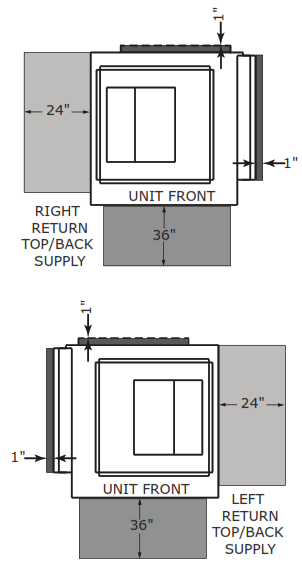
A 24-inch clearance from other mechanical and electrical equipment (where shown) is recommended for most unit configurations. This will enable panel removal from the unit for service/maintenance.
The 24-inch side clearance on GEVG 0.5-5T models is for optimal access only. Side clearance is not a requirement as most components can be accessed from the front of the unit.
A 1-inch minimum clearance between the filter rack and any obstacle is required for units in a free return application to provide proper air flow to the air-to-refrigerant coil. A 12-inch minimum clearance between the filter rack and any obstacle should be provided to properly attached ductwork.
The 1-inch dimension shown in the back of the unit represents the supply duct collar for the back supply option. This clearance is needed to clear these flanges.
Figure 2.Left return and right return/top supply (GEVG)
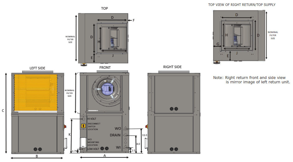
Table 6.Dimensional data left return and right return/top supply (GEVG)
| Unit | Cabinet | Duct Collar | Duct Collar Location | Blower Opening | Hi Volt | Nominal Filter Size | W.I. NPTI | W.O. NPTI | Drain NPTI | |||||
| Width | Depth | Height | ||||||||||||
| A | B | C | D | E | F | G | H | J | K | |||||
| 006-012 | 19.0 | 19.0 | 30.00 | 11.38 | 3.70 | 1.40 | 3.50 | 8.00 | 7.70 | 12.25 | 14 x 16 | 1/2 | 1/2 | 3/4 |
| 015-018 | 21.5 | 21.5 | 34.00 | 13.25 | 4.00 | 1.00 | 3.50 | 10.50 | 9.60 | 14.25 | 16 x 19 | 1/2 | 1/2 | 3/4 |
| 024-030 | 21.5 | 23.0 | 36.00 | 13.25 | 4.75 | 0.63 | 3.50 | 10.50 | 11.30 | 15.25 | 17 x 20 | 3/4 | 3/4 | 3/4 |
| 036-042 | 21.5 | 26.0 | 38.00 | 13.25 | 6.25 | 0.63 | 3.50 | 11.80 | 11.30 | 16.25 | 18 x 23 | 3/4 | 3/4 | 3/4 |
| 048-060 | 24.0 | 32.5 | 42.00 | 17.75 | 7.25 | 0.75 | 3.50 | 13.70 | 13.50 | 18.25 | 20 x 30 | 1 | 1 | 3/4 |
Note: Units in a free return application will require more than 1-inch clearance to provide proper air flow to the unit’s air-to-refrigerant coil.
Trane – by Trane Technologies (NYSE: TT), a global climate innovator – creates comfortable, energy efficient indoor environments for commercial and residential applications. For more information, please visit trane.com or tranetechnologies.com.
Trane has a policy of continuous product and product data improvement and reserves the right to change design and specifications without notice. We are committed to using environmentally conscious print practices.
WSHP-PRC029B-EN 01 Oct 2021
Supersedes WSHP-PRC029A-EN (Jul 2021)
©2021 Trane![]()


