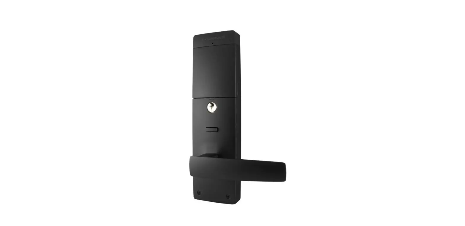
GAINSBOROUGH Suits 35mm to 45mm Door Thickness Lock
Overview
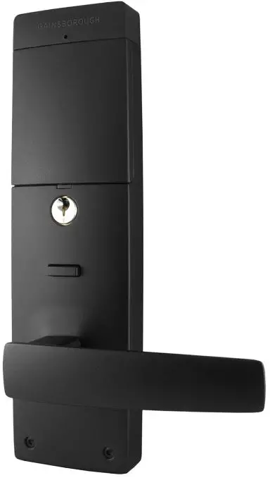
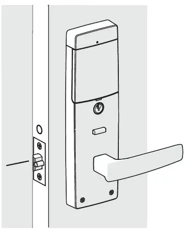
External View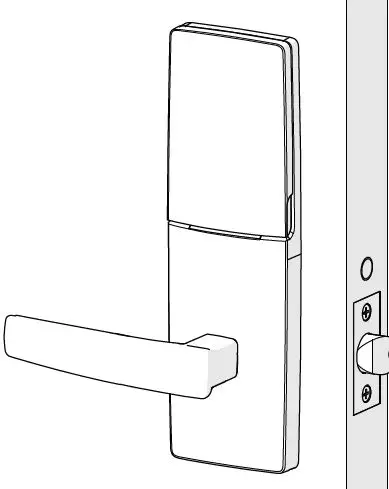
Exploded View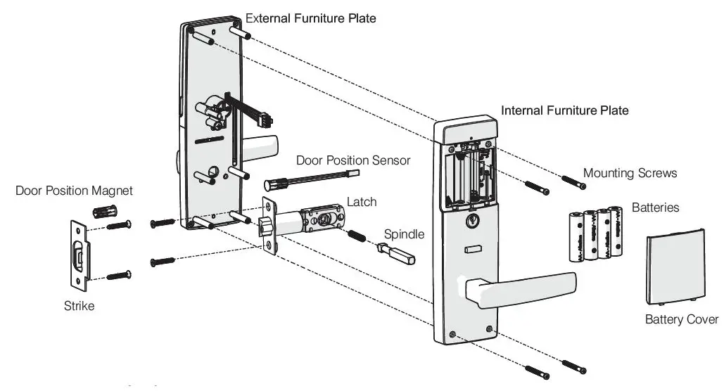
Installation Instructions
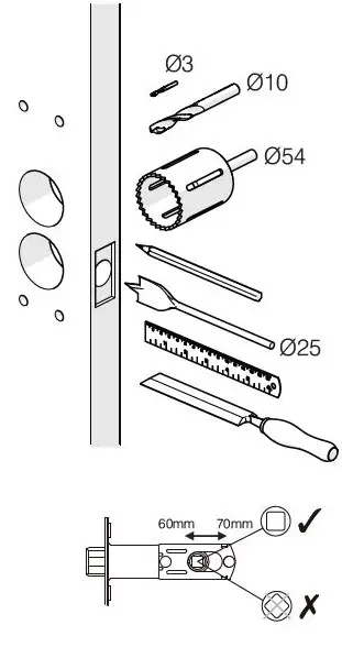
Step 1: Prepare the Door
Fold template where indicated.
- Position the template on the door edge at desired lock/latch height.
- Firmly hold the template and mark the latch height and hole positions at desired backset.
- Reverse the template fold and mark the other side of the door.
- Measure the door thickness and mark the center on the “latch height” marking.
- Drill Ø25mm latch hole. Note: it is important to drill this hole squarely.
- Drill pilot holes. (suggested size Ø3 mm) Then enlarge the holes following the installation template instructions.
- Drill Ø10 mm and Ø54 mm holes from both sides of the door.
- Mark and chisel the latch faceplate to a recess of 4.0 mm. Use the latch as a template.

Step 2: Install the Latch
Install the latch with the tapered (beveled), side of the bolt facing towards the door jamb when the door is open.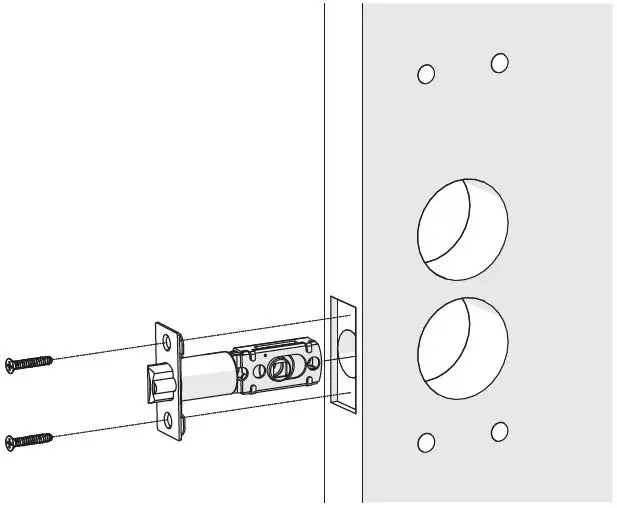
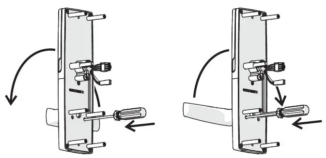
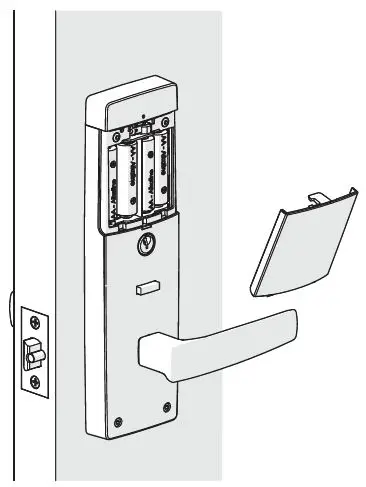
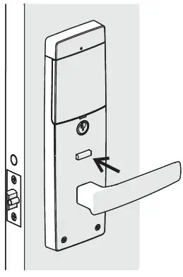
Step 3: Prepare the Internal Furniture
Using the supplied battery cover release tool, push through the hole to release the battery cover to expose the mounting screw holes.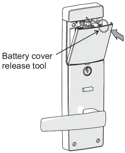
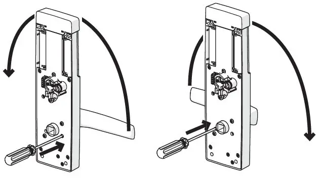
Step 4: Handing of the Internal Lever
- Rehand the lever (if necessary), by pushing the retaining plate inside the furniture as shown. (Push through the hole on the same side as the lever.)
- Then swing the lever up and over to the other direction.

NOTES:
- Carefully follow these instructions when installing.
- Do not overtighten screws.
- The use of a power driver is not recommended for screw installation.
- Fully remove the Gainsborough Freestyle prior to painting the door to avoid damaging the product’s finish
- Suitable door thickness is between 35 and 45mm
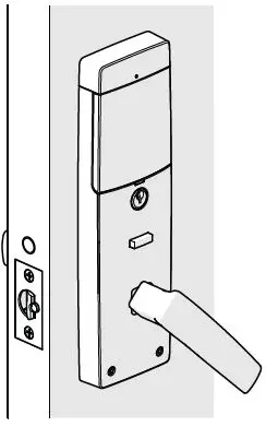
Step 5: Handing of the External Furniture
- Rehand the lever (if necessary), by pushing the retaining plate inside the furniture as shown. Push through the hole on the same side as the lever.
- Then swing the lever up and over to the other direction.

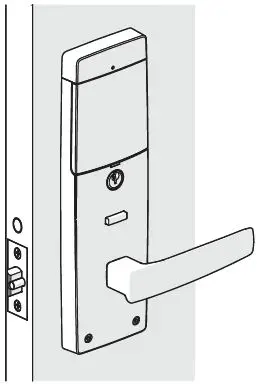
Step 6: Assemble the External Furniture to the Door
Install the External furniture onto the door as shown.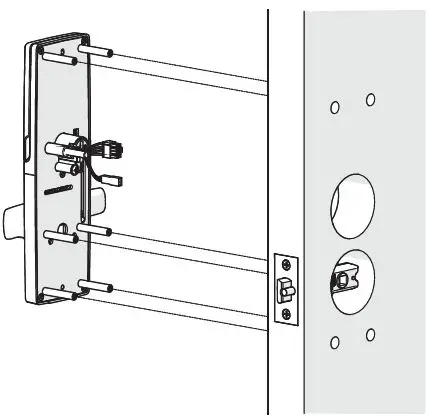
Step 7: Install the Spindle
Fit the Spindle Spring to the Spindle, and then assemble through the latch into the External Handle.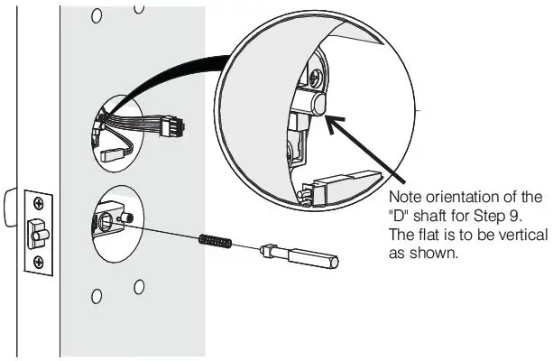
Step 8: Connect the Internal Furniture
Connect the main loom to the Internal furniture.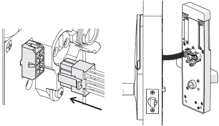
Step 9: Connect the Internal Furniture
Ensure the internal and external drive “D” shaft and socket are aligned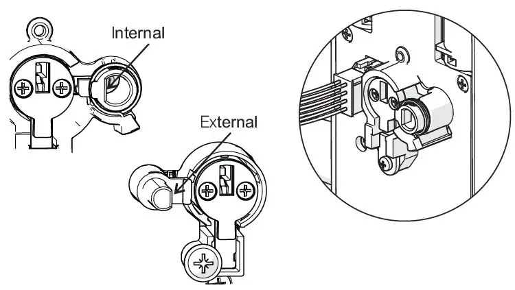
Step 10: Secure the Internal Furniture
Install the Internal furniture, taking care:
- to align the “D” shaft/socket and the latch spindle
- to ensure the loom is not pinched during assembly. This is very important.
Fasten the Internal Furniture to the External Furniture using the 4 screws supplied with the Allen Key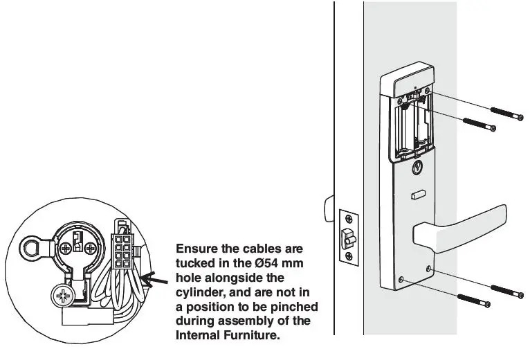
Step 11: Installation of Batteries
Install the batteries and fit the battery cover.
Use only good quality AA ALKALINE batteries.
- Note the orientation of the batteries.
- Do not mix old and new batteries.

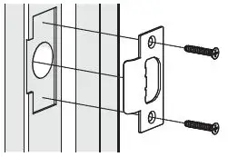
Step 12: Installation of the Strike
All door seals must be fitted prior to fitting the strike plate.
- Position the door so that the center point of the strike plate can be marked on the door frame.
- Mark and drill a Ø25mm hole to a depth of 25mm, at a corresponding height to the bolt.
- Mark and chisel recesses for the strike plate
- Fit the strike plate using the 2 screws supplied.


Door Position Sensor Installation Connected Gainsborough Freestyle only
Step 1b: Prepare Door
Using the template provided, drill a Ø10mm hole in the side of the door as shown.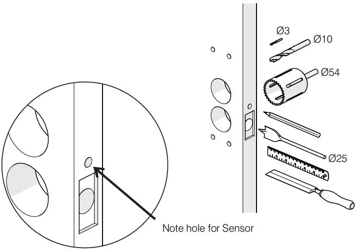
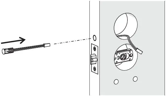
Step 2b: Install Door Position Sensor in Door
- Insert the Door Position Sensor cable through the Ø10mm hole.
- Extend it through the Ø54mm hole.
- Firmly press the magnet housing into the door edge until the front face is flush with the door edge.

Step 3b: Connect Door Position Sensor
Connect the Door Position Sensor cable to plug in the Main cable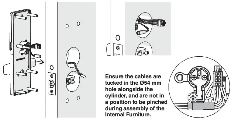
Step 4b: Install Door Position Magnet
Drill a Ø10mm hole for the Door Position Magnet and fit the magnet as shown.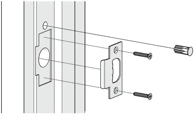
Setting First User Admin Code
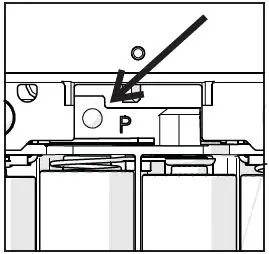
- Step 1:
Facing the Internal lockset, locate the Program button above the batteries. Press and hold for 10 sec. After approx. 10 sec., the confirmation light will blink.
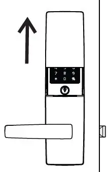
- Step 2:
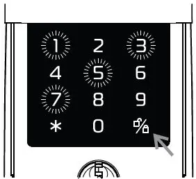
On the External side, slide cover up to energize Keypad.
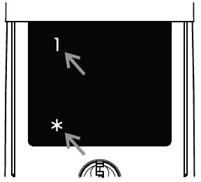
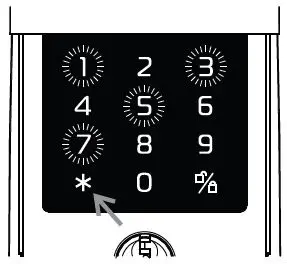
- Step 3:
Press ‘*, choose ‘1‘ then ‘*’.
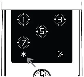
- Step 4:
Enter desired 4-digit PIN code then press ‘*’.
- Step 5:
The PIN code will repeat. Press ‘*’ again to accept PIN Press ‘ ’ to reject the PIN.
Gainsborough Freestyle Function with Keypad
- Step 1:
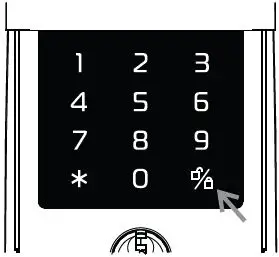
Slide cover up to energise Keypad.
Refer to User Guide for full Gainsborough Freestyle functionality. - Step 2:
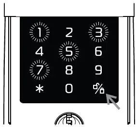
To UNLOCK – Enter 4 digit PIN code and press ‘ ‘.
Note: The lockset must be in a LOCKED state. - Step 3:
To PRIVACY LOCK – Press ‘ ‘ when leaving.
Note: The lockset must be in an UNLOCKED state. - Step 4:
To DEADLOCK – Enter 4 digit PIN code and press ‘ ‘ when leaving.
Note: The lockset must be in an UNLOCKED state.

Gainsborough Freestyle Manual Function
PASSAGE MODE
- Outside UNLOCKED
- Inside UNLOCKED

PRIVACY MODE
- Outside LOCKED
- Inside UNLOCKED
- Press the Button to engage in Privacy mode.
- Unlock by external key, keypad, or internal by operating lever.

DEADLOCK MODE
- Outside LOCKED
- Inside LOCKED
- Note: DEADLOCK can only be set via the Keypad (see above).
- Unlock by external key, keypad or internal key.

Contact Information
Al legion Australia
Freephone 1800 098 094
Freefax 1800 098 095
Email [email protected].
www.allegion.com.au.
Allegion New Zealand
Freephone 0800 477 869
Freefax 0800 477 868
Email [email protected].
www.allegion.co.nz.


