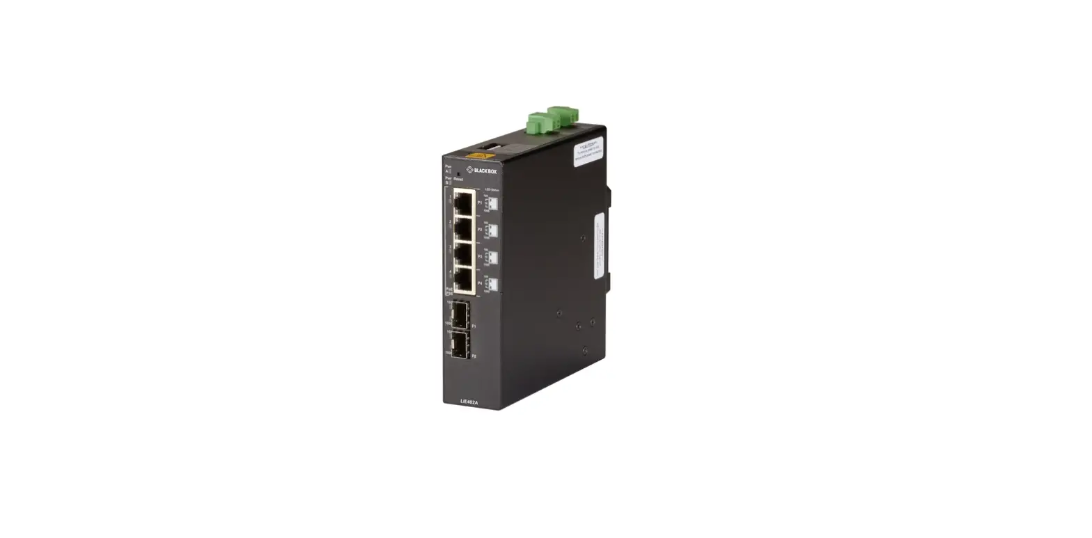
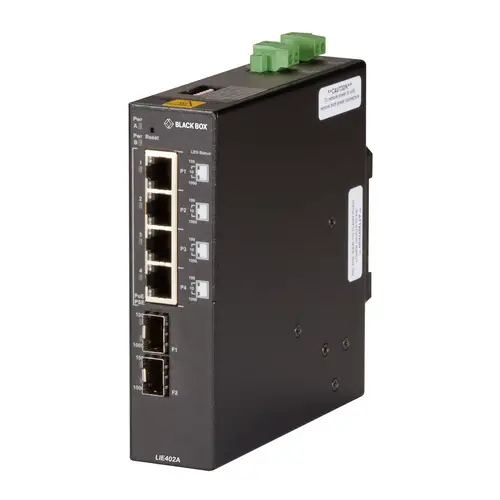
BLACK BOX LIE402A 802.3BT 60W Poe Gigabit Industrial Unmanaged Switch
SPECIFICATIONS
IEEE SPECIFICATIONS
| IEEE Specifications | |||
| Description | 802.3af PoE | 802.3at PoE+ | 802.3.bt Type 3 |
| Power available at PD | 12.95 watts | 25.5 watts | 51 watts |
| Max. power delivered by PSE | 15.4 watts | 30.0 watts | 60 watts |
| Voltage range at PSE | 44.0 to 57.0 VDC | 50.0 to 57.0 VDC | 50.0 to 57.0 VDC |
| Voltage range at PD | 37.0 to 57.0 VDC | 42.5 to 57.0 VDC | 42.5 to 57.0 VDC |
LIE402A SPECIFICATIONS
| Description | LIE402A 6-port Gigabit Industrial 802.3bt 60W POE Ethernet switch |
| Standard Compliances | IEEE 802.3, IEEE 802.3af (15.40 watts max) IEEE 802.3at (30 watts max) IEEE 802.3bt (60 watts max) |
| Environmental | REACH, RoHS, and WEEE |
| PoE Modes | IEEE Alternate A (Alt A) 4-Pair |
| Frame Size | Up to 10,240 bytes |
| DC Power Requirements | +46 to +57 VDC; inclusive of tolerance 4.46A @ 56 VDC 2 Pin Terminal (non-isolated) |
| Dimensions | 5.5″ H x 1.5″ W x 5.5″ D (13.9 x 3.8 x 13.9 cm) |
| Weight | 1.70 lb. (0.77 kg) |
| Operating Temperature | Industrial: -40 to +167° F (-40 to +75° C) Storage: -40 to +176° F (-40 to +80° C) |
| Humidity | 5 to 95% (non-condensing) |
| Altitude | -328 to +13,123 ft. (-100 to +4,000 m) (operational) |
| MTBF (hours) | 273,000 |
| COMPATIBLE TWISTED-PAIR AND FIBER SFPS | ||
| PART NUMBER | DESCRIPTION | DISTANCE |
| 100-MBPS CONNECTIONS | ||
| LFP401 | LFP400 Series Fast (155-Mbps) Extreme Temperature SFP with Extended Diagnostics – (1) 155-Mbps Multimode Fiber, 850nm, 2km, LC | 2 km |
| LFP402 | LFP400 Series Fast (155-Mbps) Extreme Temperature SFP with Extended Diagnostics – (1) 155-Mbps Multimode Fiber, 1310nm, 2km, LC | 2 km |
| LFP403 | LFP400 Series Fast (155-Mbps) Extreme Temperature SFP with Extended Diagnostics – (1) 155-Mbps Singlemode Fiber, 1310nm, 30km, LC | 30 km |
| 1000-MBPS CONNECTIONS | ||
| LFP411 | LFP410 Series Gigabit (1.25-Gbps) Extreme Temperature SFP with Extended Diagnostics – (1) 1.25-Gbps Multimode Fiber, 850nm, 550m, LC | 550 m |
| LPF412 | LFP410 Series Gigabit (1.25-Gbps) Extreme Temperature SFP with Extended Diagnostics – (1) 1.25-Gbps Multimode Fiber, 1310nm, 2km, LC | 2 km |
| LFP413 | LFP410 Series Gigabit (1.25-Gbps) Extreme Temperature SFP with Extended Diagnostics – (1) 1.25-Gbps Singlemode Fiber, 1310nm, 10km, LC | 10 km |
| LFP414 | LFP410 Series Gigabit (1.25-Gbps) Extreme Temperature SFP with Extended Diagnostics – (1) 1.25-Gbps Singlemode Fiber, 1310nm, 40km, LC | 40 km |
| LFP415 | LFP410 Series Gigabit (1.25-Gbps) Extreme Temperature SFP with Extended Diagnostics – (1) 1.25-Gbps Copper RJ-45, SerDes, 100m | 100 m |
| LFP416 | LFP410 Series Gigabit (1.25-Gbps) Extreme Temperature SFP with Extended Diagnostics – (1) 1.25-Gbps Copper RJ-45, SGMII, 100m | 100 m |
| LFP420 | LFP410 Series Gigabit (1.25-Gbps) Extreme Temperature SFP with Extended Diagnostics – (1) 1.25-Gbps Singlemode Simplex Fiber, 1550/1310nm, 10km, LC | 10 km |
| LFP421 | LFP410 Series Gigabit (1.25-Gbps) Extreme Temperature SFP with Extended Diagnostics – (1) 1.25-Gbps Singlemode Simplex Fiber, 1310/1550nm, 10km, LC | 10 km |
| LFP441 | LFP440 Series Gigabit (1.25-Gbps) SFP – (1) 1.25-Gbps Multimode Fiber, 850nm, 550m, LC | 550 m |
| LFP442 | LFP440 Series Gigabit (1.25-Gbps) SFP – (1) 1.25-Gbps Singlemode Fiber, 1310nm, 20km, LC | 20 km |
| LFP443 | LFP440 Series Gigabit (1.25-Gbps) SFP – (1) 10/100/1000-Mbps Copper RJ-45, 100m, SGMII, 100m | 100 m |
OVERVIEW
INTRODUCTION
This user manual describes the functions of the 6-port Gigabit Industrial 802.3bt 60 W PoE Ethernet switch. The LIE402A is an industrial unmanaged Ethernet switch that features two SFP uplink ports and four 10/100/1000 RJ-45 Power-over-Ethernet (PoE) ports.
6-PORT GIGABIT INDUSTRIAL 802.3BT 60 W POE ETHERNET SWITCH. The LIE402A supports IEEE 802.3af PoE, IEEE 802.3at PoE+, and IEEE 802.3bt 60 W on each RJ-45 port. The module functions can be configured using easily accessible DIP switches. The module is a Power Sourcing Equipment (PSE) that provides up to 60 W per RJ-45 port and supports frame sizes up to 10,240 bytes.
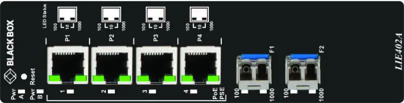
FRONT PANEL
The front of the module provides access to the RJ-45 PoE and SFP uplink ports.
RJ-45 POE AND SFP UPLINK PORTS
The RJ-45 PoE Ethernet ports support 10BASE-T, 100BASE-TX and 1000BASE-T protocols, auto-negotiation, and auto MDI/MDI-X crossover. The module features two gigabit SFP transceiver uplink ports. The SFP ports support 1000BASE-X fiber transceivers (multimode, single-mode, and single-mode single-fiber) and SGMII 10/100/1000BASE-T copper transceivers. The SFP interfaces operate in auto-negotiation and support full-duplex operation.
FRONT PANEL LAYOUT
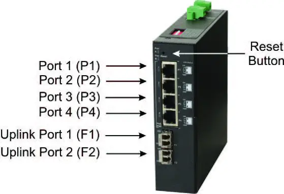
RESET BUTTON
A Reset Button is available on the front of the module to clear all buffers and memory on the module. Press and hold the reset button for more than 5 seconds to clear the buffers and memory.
INSTALLATION PROCEDURE OVERVIEW
- Configure DIP switches
- Install the Module
- Apply DC Power
- Connect Cables
- Verify Operation
INSTALLATION
STEP 1: CONFIGURE DIP SWITCHES
DIP switches are located on the top of the module. The DIP switches are used to configure modes of operation, networking features, and PoE reset.
DIP SWITCH LOCATION (TOP VIEW)

The table below provides a description of each DIP switch function.
| Switch | Description |
| SW1 | Mode of Operation |
| SW2 | |
| SW3 | Uplink Redundancy |
| SW4 | |
| SW5 | MAC Learning |
| SW6 | Forced PoE Power |
| SW7 | L2CP Control |
| SW8 | PoE Reset |
DIP Switch Definitions
SW1 and SW2 – Mode of Operation
The module supports Switch, Directed Switch, and Dual Device modes. The modes are described with MAC learning enabled. When MAC learning is disabled, unicast packets are forwarded to all ports.
| SW1 | SW2 | Function |
| LEFT | LEFT | Switch Mode (default) |
| LEFT | RIGHT | Directed Switch Mode |
| RIGHT | LEFT | Dual Device Mode – Switch Mode |
| RIGHT | RIGHT | Dual Device Mode – Directed Switch Mode |
Modes of Operation
Switch Mode
When configured for Switch Mode (default), the module operates as a standard layer 2 switch. Data flow will follow MAC address mapping.
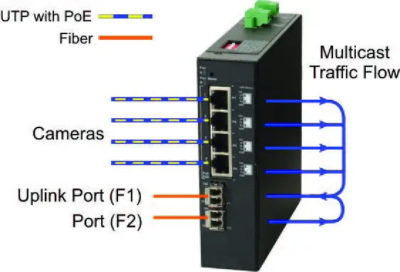
Directed Switch Mode
When configured for Directed Switch Mode, traffic from ports P1 – P4 and F2 is only forwarded to the uplink port F1, preventing the broadcast traffic from flooding other network ports. Incoming traffic from F1 follows MAC address mapping.
DIRECTED SWITCH MODE
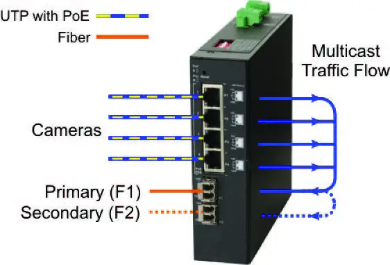
When configured for Directed Switch Mode with Uplink Redundancy (per DIP switches 3 and 4), traffic is forwarded to both the primary (F1) and secondary (F2) ports. The secondary port will block all traffic while the primary port is active. When the primary port goes down, the secondary port will be active and all traffic will be forwarded out the secondary port.
DIRECTED SWITCH MODE WITH UPLINK REDUNDANCY
Dual Device Mode
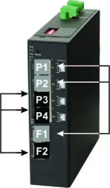
When configured for Dual Device Mode, the module is configured as two independent Layer 2 switches. Port F1 is associated with ports P1 and P2 and port F2 is associated with ports P3 and P4. Data flow will follow MAC address mapping.
DUAL DEVICE MODE
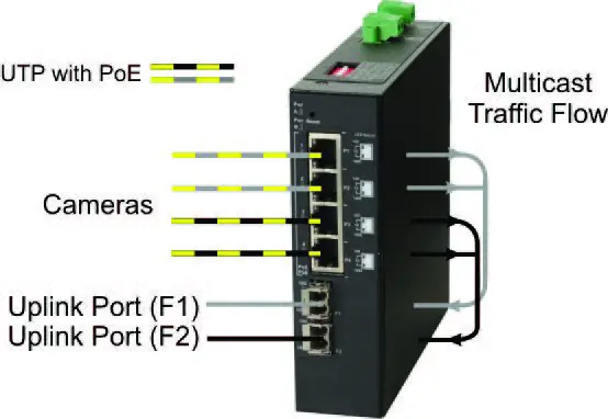
Configured for Dual Device Mode with Directed Switch Mode, the traffic from ports P1 and P2 is only forwarded to uplink port F1 and the traffic from ports P3 and P4 is only forwarded to uplink port F2. This prevents broadcast traffic from flooding other network ports. Incoming traffic from F1 and F2 follows MAC address mapping.
DUAL DEVICE WITH DIRECTED SWITCH MODE
SW3 and SW4 – Uplink Redundancy
The modes are described with MAC learning enabled. When MAC learning is disabled, the module will send data to all ports.
| SW3 | SW4 | Function |
| LEFT | LEFT | Switch Mode (default) |
| LEFT | RIGHT | Switch Mode (default) |
| RIGHT | LEFT | Redundant Mode – no return to primary (F1) |
| RIGHT | RIGHT | Redundant Mode – return to primary (F1) |
Uplink Redundancy
When configured for Uplink Redundant Mode “no return to primary”, the uplink ports operate as redundant links. A fault on the primary port F1 will cause a failover to the secondary port F2 within 50 msec. Port F1 will become the secondary port once the failure condition has been restored because “no return to primary” has been selected.
REDUNDANT UPLINK
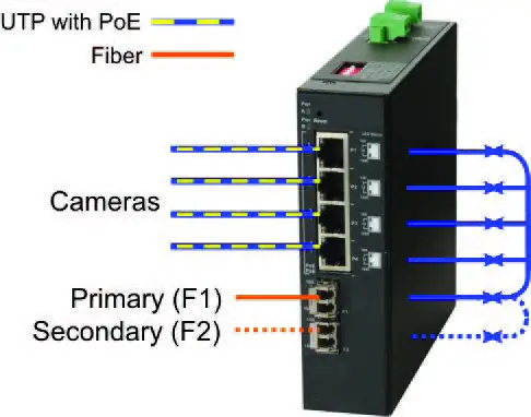
When configured for Uplink Redundant Mode “return to primary’, a fault on the primary port F1 will cause a fail over to the secondary port F2 within 50 msec. The module will return to the primary port F1 after the failure condition has been restored for 6 seconds.
SW5 – MAC Learning: MAC Learning/Off
When this DIP switch is in the LEFT “MAC Learning” position (default), all ports on the module will learn the source MAC address of each received packet and store the address so packets destined for the stored addresses can be forwarded to the appropriate port on the module. When the DIP switch is in the RIGHT “Off” position, MAC learning is turned off and all received unicast packets are forwarded to all ports.
SW6 – Forced PoE: Off/PoE Force
This DIP switch allows the PoE power to be forced ON when connected to a PD with non-standard detection characteristics. The DIP switch controls the forced capability for the RJ-45 ports on the module. When this DIP switch is in the LEFT “Off” position (default), all RJ-45 ports will automatically perform the detection, classification, and powering functions for the attached PDs. When this DIP switch is in the RIGHT “PoE Force” position, all RJ-45 ports will provide a maximum of 60 watts of power to the attached PDs. The amount of power delivered depends on the attached PDs.
SW7 – L2CP Control: L2CP Tunnel/Discard
When this DIP switch is in the LEFT “L2CP Tunnel” position (default), all received L2CP frames will be tunneled through the module. When this DIP switch is in the RIGHT “Discard” position, all received L2CP frames will be discarded.
SW8 – PSE Reset: Off/PoE Reset
The module can be configured to disable (reset) the PoE output power for 5 seconds after a loss of receive link on any uplink port. This feature is typically used to allow a PD to re-initialize after a failure on the incoming uplink. When this DIP switch is in the LEFT “Off” position (default), PoE output power does not reset on a loss of receive link on any uplink port. When this DIP switch is in the RIGHT “PoE Reset” position, the module will disable PoE output power for 5 seconds following a loss of receive link on any uplink port.
When Uplink Redundant Mode is enabled, the loss of link on either F1 or F2 will not cause the PD to be re-initialized even though the PSE Reset is enabled. The PD will be re-initialized on a loss of receive link on both uplink ports. When Dual Device Mode is enabled, the loss of receive link on an uplink port will re-initialize the PDs associated with that uplink port. Ports P1 and P2 will drop PoE power when a loss of receive link on port F1 is detected and ports P3 and P4 will drop PoE power when a loss of receive link on port F2 is detected.
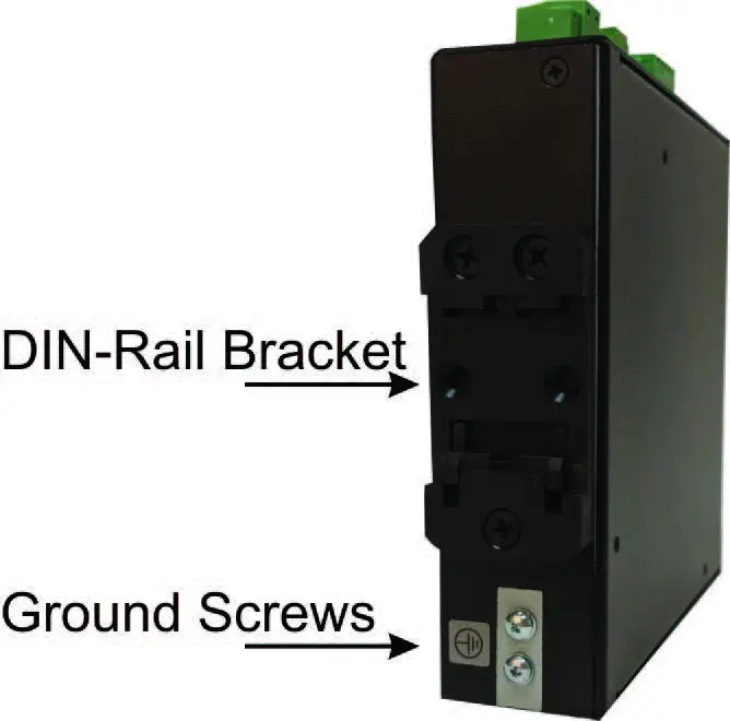
STEP 2: INSTALLING THE MODULE
The module can be DIN rail mounted using the DIN rail mounting clip on the back of the module. The bottom tab of the DIN rail clip is spring-loaded and is used to install and remove the module from the DIN rail. To install the module to the DIN rail, angle the module so the bottom edge of the spring-loaded clip is inserted on the lower edge of the DIN rail. While pushing the module up, angle the module flush to the DIN rail and insert in the upper edge of the DIN rail clip around the upper edge of the DIN rail.
To remove the module from the DIN rail, hold the module firmly while lifting the module up. Angle the top of the module away from the DIN rail, disengaging the module from the upper edge of the DIN rail.
STEP 3: APPLY DC POWER
This module is intended for installation in restricted access areas. (“Les matériels sont destinés à être installés dans des EMPLACEMENTS À ACCÈS RESTREINT”). A restricted access area can be accessed only through the use of a special key, or other means of security. The over-current protection for connection with centralized DC shall be provided in the building installation, and shall be a UL listed circuit breaker rated 20 Amps, and installed per the National Electrical Code, ANSI/NFPA-70. The LIE402A requires +50 to +57 VDC inclusive of tolerances (4.46 A @ 56 VDC maximum rated power). Be sure to provide appropriate overloading protection on the DC power source outlets used.
TOP VIEW WITH DC POWER CONNECTOR

WARNING
OnlyaDC power source that complies with safety extra-low voltage (SELV) requirements can be connected to the DC-input power supply.
WARNING REGARDING EARTHING GROUND
This equipment shall be connected to the DC supply system earthing electrode conductor or to a bonding jumper from an earthing terminal bar or bus to which the DC supply system earthing electrode is connected. This equipment shall be located in the same immediate area (such as adjacent cabinets) as any other equipment that has a connection between the earthed conductor of the same DC supply circuit and the earthing conductor, and also the point of earthing of the DC system. The DC system shall not be earthed elsewhere. The DC supply source is to be located within the same premises as this equipment. There shall be no switching or disconnecting devices in the earthed circuit conductor between the DC source and the earthing electrode conductor.
Locate the DC circuit breaker of the external power source, and switch the circuit breaker to the OFF position. Prepare a power cable using a three-conductor insulated wire (not supplied) with 12 AWG to 14 AWG thickness. Cut the power cable to the length required.
Strip approximately 3/8 of an inch of insulation from the power cable wires. The ground wire may need additional insulation removed to secure it to the grounding screws.
Connect the ground wire to the grounding screws on the back of the module.
GROUND SCREW LOCATION
Connect the power wires to the module by fastening the stripped ends to the DC power connector.
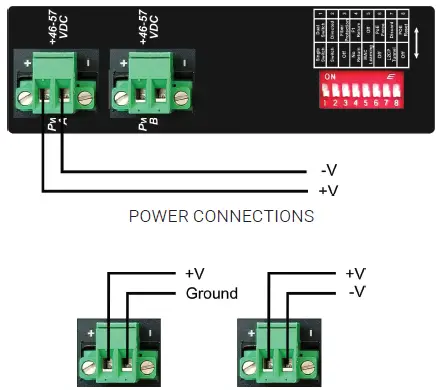
WARNING: The positive lead of the power source must be connected to the “+” terminal on the module and the negative lead of the power source to the “-“ terminal on the module as shown above. The power connections on the module are non-isolated.
WARNING: Note the wire colors used in making the positive, negative and ground connections. Use the same color assignment for the connection at the circuit breaker.
Connect the power wires to the circuit breaker and switch the circuit breaker ON. If any modules are installed, the Power LED(s) will indicate the presence of power.
During the installation, ensure that the ground potentials are maintained throughout the system connections. This includes but is not limited to the power source ground and any shielded cabling grounds.
WARNING!!!
NEVER ATTEMPT TO OPEN THE CHASSIS OR SERVICE THE POWER SUPPLY. OPENING THE CHASSIS MAY CAUSE SERIOUS INJURY DEATH. THERE ARE NO USER-REPLACEABLE OR SERVICEABLE PARTS IN THIS UNIT.
Make sure to disconnect both power connectors and the ground cables before removing the equipment.
STEP 4: CONNECT CABLES
- Insert the Gigabit SFP fiber or SGMII 10/100/1000BASE-T copper transceiver into the SFP receptacle on the front of the module. NOTE: The release latch of the SFP fiber transceiver must be in the closed (up) position before insertion.
- Connect an appropriate multimode or singlemode fiber cable to the fiber port on the front of the module. It is important to ensure that the transmit (TX) is attached to the receive side of the transceiver at the other end and the receive (RX) is attached to the transmit side. When using single-fiber (SF) models, the TX wavelength must match the RX wavelength at the other end and the RX wavelength must match the TX wavelength at the other end.
- Connect the Ethernet 10/100/1000 RJ-45 port using a Category 5 or better cable to an external 10BASE-T, 100BASE-TX or 1000BASE-T Ethernet PD device.
STEP 5: VERIFY OPERATION
Verify the module is operational by viewing the LED indicators.
LED INDICATOR LOCATION
| Power LED Indicators | ||
| Legend | Indicator | Description |
| Pwr A and Pwr B | OFF | Unit not powered |
| Green – ON | Unit powered | |
| Green – Blinking at 1Hz | Unit powered and indicates the Reset switch has been depressed for the required length of time causing the clearing of all buffers and memory on the module. | |
Power LED Indicators
| Uplink Ports LED Indicators | ||
| Legend | Indicator | Description |
| 10 (100+1000) | OFF | No link |
| Green – ON | Port linked at 10 Mbps | |
| Green – Blinking at 10Hz | Port data activity at 10 Mbps | |
| Green – Blinking at 1Hz | Port linked at 10 Mbps and in redundant secondary mode | |
|
100 | OFF | No link |
| Green – ON | Port linked at 100 Mbps | |
| Green – Blinking at 10Hz | Port data activity at 100 Mbps | |
| Green – Blinking at 1Hz | Port linked at 100 Mbps and in redundant secondary mode | |
|
1000 | OFF | No link |
| Amber – Blinking at 1Hz | Port not linked at 1000 Mbps and receiving AN Remote Fault | |
| Green – ON | Port linked at 1000 Mbps | |
| Green – Blinking at 10Hz | Port data activity at 1000 Mbps | |
| Green – Blinking at 1Hz | Port linked at 1000 Mbps and in redundant secondary mode | |
Uplink LED Indicators
NOTE: 10 Mbps and 100 Mbps operation is supported when using an SGMII 10/100/1000BASE-T copper transceiver.
| RJ-45 Ports LED Indicators | ||
| Legend | Indicator | Description |
|
10 (100+1000) | OFF | No link |
| Amber -ON | Port linked at 10 Mbps Half-duplex | |
| Amber – Blinking at 10Hz | Port data activity at 10 Mbps Half-duplex | |
| Green – ON | Port linked at 10 Mbps | |
| Green – Blinking at 10Hz | Port data activity at 10 Mbps | |
|
100 | OFF | No link |
| Amber -ON | Port linked at 100 Mbps Half-duplex | |
| Amber – Blinking at 10Hz | Port data activity at 100 Mbps Half-duplex | |
| Green – ON | Port linked at 100 Mbps | |
| Green – Blinking at 10Hz | Port data activity at 100 Mbps | |
|
1000 | OFF | No link |
| Amber -ON | Port linked at 1000 Mbps Half-duplex | |
| Amber – Blinking at 10Hz | Port data activity at 1000 Mbps Half-duplex | |
| Green – ON | Port linked at 1000 Mbps | |
| Green – Blinking at 10Hz | Port data activity at 1000 Mbps | |
|
PoE/PSE | OFF | Port PSE inactive |
| Amber – ON | Port PSE inactive due to power demand exceeding the power source | |
| Green – single blink | Powered by 802.3af PoE 15W | |
| Green – two blinks | Powered by 802.3at PoE 30W | |
| Green – three blinks | Powered by High-Power PoE 60W | |
RJ-45 LED Indicators
NOTE: The PSE LED may turn Amber (ON) when a non-PD device is connected to the port.
NOTE: When disconnecting and reconnecting the cable from the RJ-45 PSE ports, it is required to wait at least 5 seconds before reconnecting the cable to the RJ-45 PSE port.
APPENDIX A: REGULATORY INFORMATION
A.1 FCC STATEMENT
This equipment generates, uses, and can radiate radio-frequency energy, and if not installed and used properly, that is, in strict accordance with the manufacturer’s instructions, may cause interference to radio communication. It has been tested and found to comply with the limits for a Class A computing device in accordance with the specifications in Subpart B of Part 15 of FCC rules, which are designed to provide reasonable protection against such interference when the equipment is operated in a commercial environment. Operation of this equipment in a residential area is likely to cause interference, in which case the user at his own expense will be required to take whatever measures may be necessary to correct the interference. Changes or modifications not expressly approved by the party responsible for compliance could void the user’s authority to operate the equipment. This digital apparatus does not exceed the Class A limits for radio noise emission from digital apparatus set out in the Radio Interference Regulation of Industry Canada.
APPENDIX B: DISCLAIMER/TRADEMARKS
B.1 DISCLAIMER
Black Box Corporation shall not be liable for damages of any kind, including, but not limited to, punitive, consequential or cost of cover damages, resulting from any errors in the product information or specifications set forth in this document and Black Box Corporation may revise this document at any time without notice.
B.2 TRADEMARKS USED IN THIS MANUAL
Black Box and the Black Box logotype and mark are registered trademarks of Black Box Corporation. Any other trademarks mentioned in this manual are acknowledged to be the property of the trademark owners.


 User Manual")


