![]() User Manual
User Manual
ELECTRA-T16
16 Port Gigabit Layer2 Managed PoE Switch
Installation manual introduction
The Product installation manual mainly describes ELECTRA-T16 PoE switch hardware features, installation methods, and precautions during the installation
This manual includes the following chapters:![]() NOTE: To avoid potential device damage and personal injury, read the related information in this manual before installing the device.
NOTE: To avoid potential device damage and personal injury, read the related information in this manual before installing the device.
The term “switch” mentioned in this manual, unless otherwise specified, refers to 16- port full Gigabit managed PoE switch, hereinafter referred to as ELECTRA-T16 .
Some pictures for the schematic, the product itself and pictures may be different The contents of this document may be updated from time to time due to product version upgrades or other reasons. Unless otherwise agreed, this document is provided as a guide only, and all statements, information and recommendations in this document do not
constitute any form of warranty.![]() This icon indicates the items to be cautioned in the operation. If the operation is wrong, the equipment may be damaged and other adverse consequences.
This icon indicates the items to be cautioned in the operation. If the operation is wrong, the equipment may be damaged and other adverse consequences.
Chapter 1 Product Introduction
1.1Product Introduction
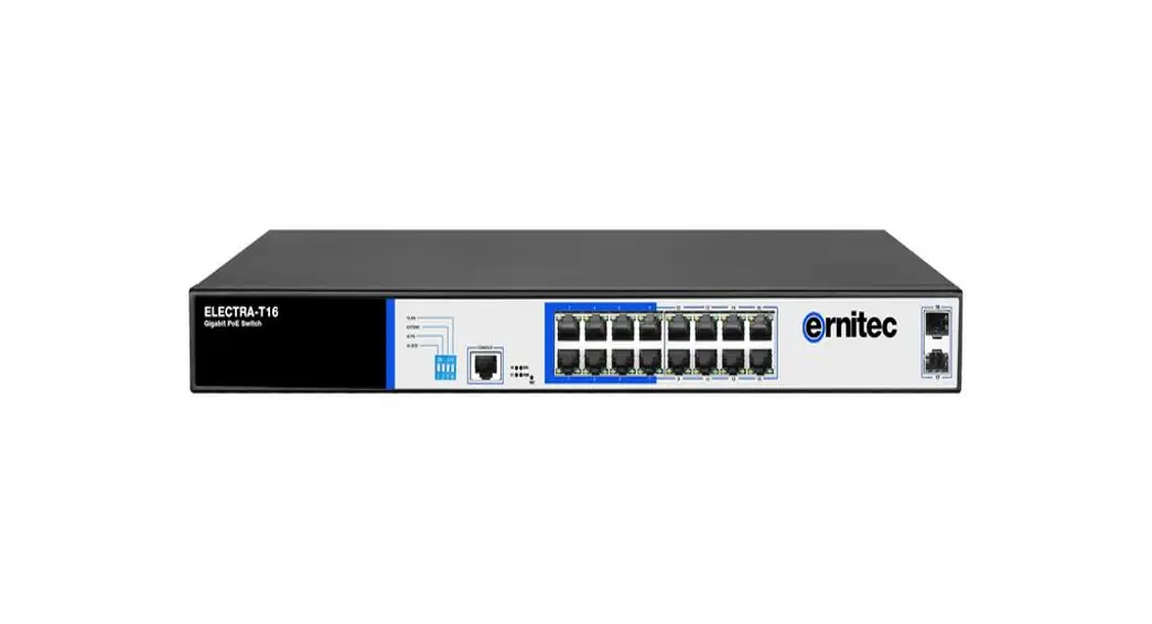
ELECTRA-T16 is managed PoE switch designed for security transmission and WIFI coverage. It can meet the POE power supply requirements of WIFI AP, IP camera, WIFI bridge, IP phone and other types of equipment. The product adopts a new generation of high-performance hardware and software platform to provide flexible, cost-effective access and Gigabit uplink ports, complete security protection mechanism, complete ACL/QoS policy and rich VLAN functions, easy to manage and maintain, and
meet users’ requirements for network equipment easy to manage, high security and low-cost , it is applicable to network access, aggregation, and core application scenarios of campus, hotel, and enterprise campus.
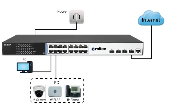
PoE (Power over Ethernet) refers to the power over Ethernet technology. It refers to the transmission of data signals to some IP-based terminals (such as IP phones, wireless access point APs, network cameras, etc.) and also provide DC power supply technology. These devices that accept DC power supply are called powered devices (PD, Powered Device)
1.2Packing List
Open the package and check the list below
| Commodity | Quantity | Description |
| PoE switch | 1pcs | No |
| Power cord | 1pcs | Optional |
| Bracket | 2pcs | Fixed on rack mount |
| User manual | 1 pcs | Guide users to install switch |
1.3Appearance
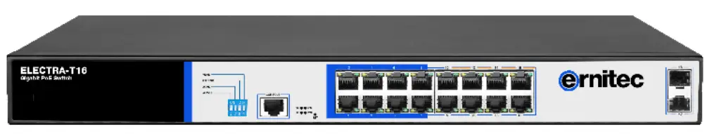
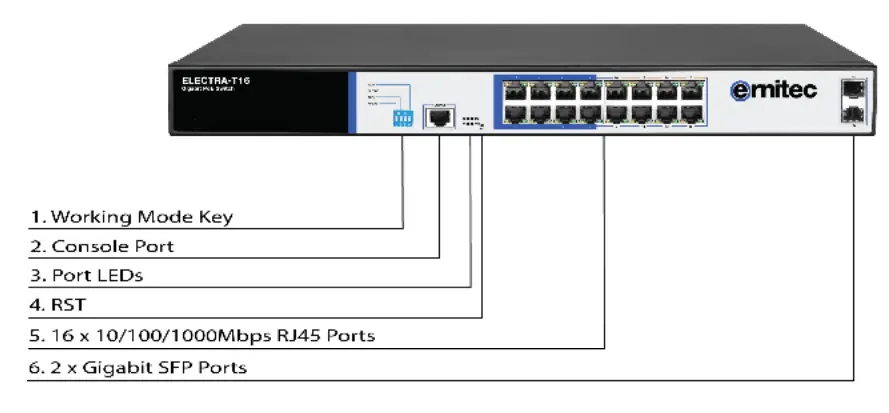
- Front Panel
Including indicators, RJ45 port, shortcut buttons, RST button, SFP port, CONSOLE port, as shown in Figure 1.1 below
Indicators
ELECTRA-T16 The indicator working status is shown as the following table
| Indicator | Title | color | Work state | Description |
| PWR | Power indicator | red | Solid | Power is normal |
| off | No power, the power switch is not turned on, power supply is abnormal | |||
|
POE |
POE power indicator |
yellow | solid | The corresponding RJ45 port is connected to the powered device and the power supply is normal |
| off | The corresponding RJ45 port is not connected to the powered device or the power supply is abnormal | |||
| LINK/ACT | Connection indicator | green | Blinking | A valid link is established |
| off | An invalid link is established | |||
| SYS | System indicator | green | Blinking | System is functioning properly |
| off | System is functioning improperly Software is damaged |
DIP switch function
AI QOS: Improve video data processing capabilities and improve the monitoring of Caton and Mosaic phenomena in the network
AI Extend: 1-8 port rate down to 10Mbps, but the transmission distance up to 250 meters
AI VLAN: Isolating ports 1-16 from each other, suppress network storms effectively and improve network performance
AI power supply: Detect PD, power failure and restart dead equipment
- RJ45 Port
ELECTRA-T16 supports 16 10/100/1000 Mbps ports, both supporting IEEE802.3af and IEEE802.3at standard POE power supply. - SFP Port
ELECTRA-T16 provides 2 Gigabit SFP optical module expansion slots (17, 18) for plugging Gigabit SFP modules - RST Button
When the switch is powered on, press the button with needle and release the device to enter the restart state. When the SYS light is turned on again, the device restarts. When the switch is powered on, press the button for 5 seconds or more to release the button device to enter the reset status, when SYS lights up again, the device resets successfully. 。 - Console Port
The Console port is used for connecting to the serial port of a computer or other terminal to manage or configure the switch. 。 - Back Panel
Includes: power socket, ground

- Power socket
The power supply to the switch ELECTRA-T16 should be 100-240V~ 50/60Hz AC power. - Ground terminal
Please use a wire to ground so that preventing lightning strikes. To avoid product lightning strikes and extend the life of the product
Chapter 2 Product Installation
2.1 Installation Precautions
![]() Note: To avoid damage to the equipment and personal injury caused by improper use, please observe the following precautions.
Note: To avoid damage to the equipment and personal injury caused by improper use, please observe the following precautions.
- Installation safety precautions
- The power is kept off during the installation process. Wear an ESD preventive wrist strap and ensure that the ESD-preventive wrist strap is in good touch with the skin to avoid potential safety hazards. ;
- The switch can work normally under the correct power supply. Please confirm that the power supply voltage matches the voltage indicated by the switch. ;
- Before powering on the switch, please make sure that the power circuit is not overloaded, so as not to affect the normal operation of the switch and even cause unnecessary damage ;
- To avoid the risk of electric shock, do not open the case while the switch is working, even if it is not charged, do not open it by yourself.;
- Before cleaning the switch, pull out the power plug of the switch. Do not wipe with a moist fabric. Do not use liquid to clean.
- Temperature and humidity
In order to ensure long-term stable operation of the switch and prolong its service life, please maintain a certain temperature and humidity in the environment. Excessively high or too low ambient humidity may cause leakage, deformation or even corrosion of metal parts. If the temperature is too high, the aging process of the insulation material will be accelerated, which will seriously affect the service life of the equipment. Normal operation and storage temperature / humidity of this series of switches
As below
| Environmental description | Temperature | Relative humidity |
| Working Environment | 0℃~40℃ | 10%~90% RH Non- condensing |
| Storage environment | -40℃~70℃ | 5%~90% RH Non- condensing |
- Altitude
 Products with this mark are only suitable for safe use in areas below 2000m.
 - Dust-proof
Dust falling on the surface of the switch can cause electrostatic adsorption and poor contact of the metal contacts. Although the device itself has made certain measures in anti-static, when the static electricity exceeds a certain strength, it will still cause fatal damage to the electronic components on the internal circuit board. To avoid the static electricity affecting the normal operation of the device, please pay attention to the following: Regular dust removal to keep indoor air clean; Confirm that the equipment is well grounded to ensure the smooth transfer of static electricity 。 - Electromagnetic interference
Electromagnetic interference will affect the internal components such as capacitance, inductance and other electronic components by capacitive coupling, inductive coupling, impedance coupling, etc. To reduce the adverse effects caused by electromagnetic interference, please pay attention to the following:
The power supply system takes necessary measures against grid interference;
The switch should be away from high-frequency, high-power, high-current equipment, such as wireless transmitters;
Take electromagnetic shielding measures when necessary 。 - Lightning protection needs
When a lightning strike occurs, a strong current is generated in an instant, and the air in the discharge path is instantaneously heated to 20,000 degrees Celsius, and an instantaneous large current is enough to cause fatal damage to the electronic device. For better lightning protection, please note the following: Confirm that the rack is in good contact with the ground; Make sure the power outlet is in good contact with the ground; Reasonable wiring to avoid internal induction lightning; Signal lightning protector is recommended for outdoor wiring - Installation station requirements
Regardless of whether the switch is installed in a rack or on another horizontal workbench, be aware of the following: Make sure the rack or workbench is stable, strong, and can withstand at least 5.5Kg weight; Make sure the rack has a good cooling system, or maintain good indoor ventilation; Make sure the rack is well grounded, the power outlet and switch are within 1.5 meters - Prepare tools for installation
You may need to use a screwdriver during installation, electrostatic wrist strap, fiber optic cable and other tools to prepare yourself
2.2 Product installation
19-inch standard rack installation
PS1016S is designed according to the standard 19-inch rack size, you can easily install to the rack, the specific installation steps are as follows:
- Check rack grounding and stability ;
- Install the two L-brackets in the accessory on each side of the switch panel and secure with the screws provided in the accessory
- place the switch in an appropriate place in the rack and be supported by the bracket. Screw the L-shaped bracket to the guide groove fixed on both ends of the rack to ensure that the switch is stable and horizontally installed on the rack
![]() Note:
Note:
Good grounding rack is anti-static equipment, anti-leakage, lightning protection, anti-jamming important guarantee, so to ensure that the rack ground wire properly installed;
Installation equipment within the rack from the bottom up, to avoid overload installation; Avoid placing other heavy objects on switch to avoid accidents; Ensure heat dissipation and air circulation.
Chapter3 Hardware connection
3.1RJ45 port connection
Connect the RJ45 port of the switch and the corresponding network device via cables, the POE power supply function of the switch is default enabled on the downlink port of the switch, which can be used for IEEE802.3af or IEEE802.3at standards powered devices such as APs, bridges, and network cameras
![]() Note:
Note:
When the switch connected workstations, servers, routers or other Ethernet devices the cable length should be within 100 meters; The Auto-MDI / MDIX Ethernet interface is enabled by default. Category 5,the standard network cable or crossover cable can be used for Ethernet connection. Do not connect the RJ45 port to the phone line
3.2SFP Port connection
ELECTRA-T16 SFP port only support Gigabit fiber module. Recommended use of standard SFP module products The process of installing a fiber module on a switch is as follows: First, grasp the optic fiber module from the side, insert it smoothly along the SFP port slot until the optic fiber module and switch are in close contact; Second, confirm the Rx and Tx ports of the fiber module when connecting, insert one end of the fiber into the Rx and Tx ports correspondingly, ensure that the Tx and Rx ends of the interface are connected correctly and the other end of the fiber is connected to another device; Third, please check the corresponding indicator light status after power on. If the light blinking that the link is properly connected, if the light is off , the link is failure, pleas check the line to confirm that the corresponding equipment is enabled.
![]() Note:
Note:
Does not allow excessive bending fiber, the radius of curvature should not be less than 10cm; Ensure the cleanliness of the fiber surface; Please do not look directly into the optical fiber connector with your eyes as this may cause eye injury
3.3 Check before power on
Check whether the outlet power supply meets the switch specifications;
Check the power, switches, racks and other equipment have been properly grounded;
Check whether the switch and other network devices are connected properly
3.4 Device initialization
The switch automatically initializes when the power switch is turned on.
Indicator will appear the following situation:
After the power is turned on, the power indicator remains on, the other indicator is off at this time;
After about 1 second, all lights except for the power light turn on for about 35 seconds and then turn off; when the SYS light goes flashing, the system runs normally
Port LEDs indicates the connection status of each port, indicating that the switch has started to work normally
3.5Web Login
Step1 、In the normal operation of the device, connect the computer to the switch’s RJ45 port by network cables
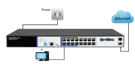
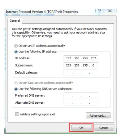
Step 2 、 Manually changed the computer IP address to 192.168.254.X (X is 2 ~ 254), subnet mask is 255.255.255.0
Step3、Open computer’s browser, type 192.168.254.1 in the address box, hit the Enter key
Step4、Enter the default username and password “admin” and then click Login

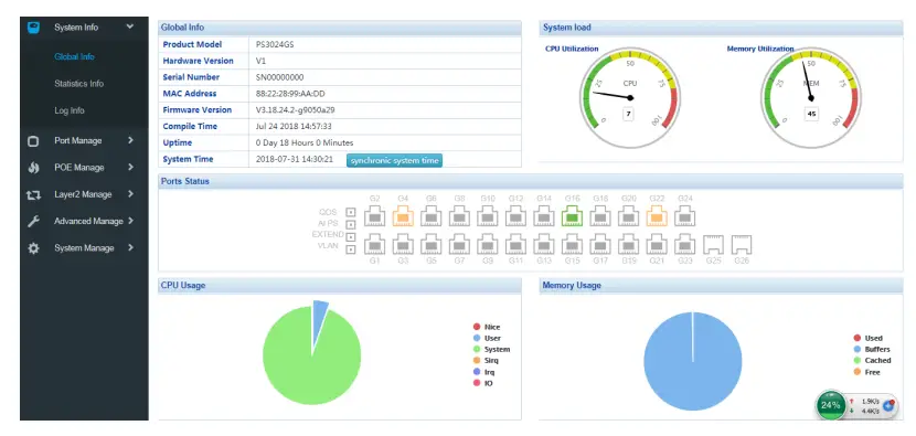
Step5、Entered the switch web management interface successfully when you see picture as below, you can begin to configure the switch
 Chapter 4 Hardware Specifications
 Chapter 4 Hardware Specifications
4.1 Hardware Specifications
| Network standard | IEEE 802.3i IEEE 802.3u IEEE 802.3x IEEE 802.3ab IEEE 802.3af IEEE 802.3at |
| Port | 16 10/100/1000Mbps RJ45 port |
| 2 gigabit SFP | |
| 1 Console | |
| PoE | 16 个 10/100/1000Mbps RJ45 port support PoE+ |
| Max 150W | |
| Single port max 46W | |
| LEDs | 18 Link/Act LEDS |
| 16 POE LEDs | |
| 1 SYS LED | |
| 1 Power LED | |
| Performance | Forwarding mode: store and forward |
| Bandwidth:36Gbps | |
| Packet forwarding rate:23.8Mpps | |
| 8K MAC address table | |
| Lightning protection | 6KV |
| Input | 100-240V/50-60Hz |
| Dimension (L×W×H) | 440mm×180mm×44mm |
4.2 Software Specifications
| Protocol standard | IEEE 802.3:Ethernet Media Access Control (MAC) Protocol IEEE 802.3i:10BASE-T Ethernet IEEE 802.3u:100BASE-TX Fast Ethernet IEEE 802.3ab:1000BASE-T Gigabit Ethernet IEEE 802.3z:1000BASE-X Gigabit Ethernet (fiber) IEEE 802.3ad:Standard method for performing link aggregation IEEE 802.3x:flow control IEEE 802.1p:LAN Layer 2 Qos/Cos protocol for traffic priority (multicast filtering) IEEE 802.1q:VLAN IEEE 802.1d:STP Spanning tree IEEE 802.1s:MSTP Spanning tree IEEE 802.1w:RSTP Spanning tree IEEE 802.3af IEEE 802.3at |
| Shortcut function | One key AI VLAN |
| One key AI Extend(1-8 port 250meters PoE distance) | |
| One key AI PoE | |
| One key Q0S (Video priority) | |
| DHCP | Support DHCP Snooping |
| VLAN | Support 4K VLAN |
| Support 802.1Q VLAN、MAC VLAN ,IP VLAN | |
| Voice VLAN | |
| MAC address table | Comply the IEEE 802.1d standard |
| Support MAC address learning and aging automatically | |
| Support static, dynamic, filter address table | |
| Safety | Password protection |
| Support based on the port number, IP address, MAC address restrictions on user access | |
| Support HTTPS、SSL V3、TLS V1、SSH V1/V2 | |
| Support IP-MAC-PORT ternary binding | |
| Support ARP protection, IP source protection, DoS protection |
| Support DHCP Snooping DHCP attack protection | |
| Support 802.1X certificated AAA | |
| Support port security, port isolation | |
| Support CPU protection | |
| POE management | Support POE power limit |
| Support POE chip status view | |
| Support setting PoE port priority | |
| Support setting PoE power supply time period | |
| Access control (ACL) | Support L2 (Layer 2) ~ L4 (Layer 4) packet filtering |
| Support port mirroring, port redirection, flow rate limiting, QoS re-marking | |
| Quality of Service (QoS) | Support 8 port queue |
| Support port priority, 802.1p priority, DSCP priority | |
| Support SP、RR、WFQ Priority scheduling algorithm | |
| Spanning Tree | Support STP(IEEE 802.1d),RSTP(IEEE 802.1w) and MSTP(IEEE 802.1s) protocol |
| Support loop protection, root bridge protection, TC protection, BPDU protection, BPDU filtering | |
| Multicast | Support IGMP v1/v2 Snooping |
| Support fast leave mechanism | |
| Support multicast VLAN | |
| Supports multicast filtering, packet statistics, and unknown multicast discards. | |
| Storm suppression | Support multicast suppression |
| Support broadcast suppression | |
| Support unknown unicast suppression | |
| Link aggregation | Support static aggregation |
| Support dynamic aggregation |
| Support IP, MAC, and hybrid load balancing modes | |
| Supports up to 32 aggregation groups | |
|
IPv6 | Support IPv6 Ping、IPv6 Tracert、IPv6 Telnet |
| Support IPv6 SSH 、IPv6 SSL | |
|
Management and maintenance | Support WEB network management (HTTP, HTTPS, SSL V3) |
| Support CLI (Telnet, SSH V1/V2, local serial port) | |
| Support SNMP V1/V2/V3 | |
| Support LLDP、RMON | |
| Support ARP protection, IP source protection, DoS protection | |
| Support CPU monitoring, memory monitoring | |
| Support system log, grading warning | |
| Support Ping, Tracer detection, cable detection |
![]()


 Managed Switch Cli User Manual")


