![]() User manual
User manual SW2624POE-MGF-250
24 Port Gigabit Layer 2 PoE Switch
Installation manual introduction
The Product installation manual mainly describes PoE switch hardware features, installation methods, and precautions during the installation
This manual includes the following chapters:
Chapter 1: Product Introduction. Briefly describes the basic features,
Detailed hardware & software specifications of the switch and the appearance details.
Chapter 2: Product Installation. Guide the switch hardware installation methods and precautions.
Chapter 3: Hardware Connections. Guide the connection between switches and other devices and precautions.
Chapter 4: Packaging and product usage suggestions.
Chapter 1: Product Introduction
1.1 Products description
Device is managed PoE switch for security transmission and WIFI coverage, meet the need of PoE power supply for WIFI AP, IP-camera, WIFI bridge, IP phones and other types of equipment. New generation of high-performance hardware and software platforms are used, providing flexible, cost-effective full Gigabit access and uplink ports, complete security mechanisms, improved ACL / QoS strategy and rich VLAN capabilities. It is easy to manage and maintain, meet the users’ requirements for network equipment easy to manage, high security and low cost. Supporting Apollo Cloud One-stop Management Platform, realizing status checking and management monitoring functions, suitable for campus, Hotel and enterprise park network access, convergence, core multi-application scenarios
1.2 Product Features
- Full Gigabit Port
24 1000Mbps RJ45 ports (support PoE power supply) with 2 Gigabit SFP ports, Data transmission is not jammed. - Realtek chip, the performance is more stable and powerful
Realtek high-performance chip can greatly improve network data processing rate - Convenient operation
- AI VLAN mode: Separating 1-8 ports from each other, can effectively restrain network storm and improve network performance.
- AI Extend mode: Designed for monitoring application scenarios, 1-8 ports support 250 meters long distance power supply.
- AI PoE mode: automatically check, reboot the device while find it fake dead
- AI QoS mode: video data first, more fluent transmission
- Support Apollo Cloud Platform One-stop Management Support cloud platform for resource visualization management of switches and downloaded PD devices, make operation and maintenance management easy
1.3 product specification
Hardware Specifications
| Chipset | Realtek High Performance Chipset |
| Flash | 16MB |
| RAM | 128M DDR |
| Network | IEEE 802.3i IEEE 802.3u IEEE 802.3x IEEE 802.3ab IEEE 802.3af IEEE 802.3at |
| Port | 2410/100/1000Mbps RJ45 ports |
| 2 Gigabit SFP ports | |
| 1 Console port | |
| PoE | 24 10/100Mbps RJ45 port support PoE+ |
| Max 250W | |
| Single port max 46W | |
| LEDs | 26 Link/Act LEDs |
| 24 POE LEDs | |
| 1 Power LED | |
| 1 SYS LED | |
| Performance | Forwarding mode: store and forward |
| Performance | Switch Volume (Full-duplex) :52Gbps |
| Packet forwarding rate:38.688Mpps | |
| 8K MAC address table | |
| lightning protection | ±6KV |
| ESD | No barrier: ±6KV Air:±8KV |
| Input | 100-240V/50-60Hz |
| Dimension (L×W×H) | 440mm×180mm×44mm |
Software Specifications
| Network standard | IEEE 802.3: Ethernet Media Access Control (MAC) protocol IEEE 802.3i:10BASE-T Ethernet IEEE 802.3u:100BASE-TX fast Ethernet IEEE 802.3ab:1000BASE-T gigabit Ethernet IEEE 802.3z:1000BASE-X gigabit Ethernet (fiber) IEEE 802.3ad: comply link aggregation standard IEEE 802.3x: flow control IEEE 802.1p: About the traffic priority of the second layer of Qos / Cos protocol (multicast filtering) IEEE 802.1q:VLAN Bridge operation IEEE 802.1d:STP spanning tree IEEE 802.1s:MSTP spanning tree IEEE 802.1w:RSTP spanning tree |
| IEEE 802.3af IEEE 802.3at | |
| Shortcut function | One key VLAN |
| One key Exnted(1-8 port 250meters PoE distance) | |
| One key QoS (Video priority) | |
| One key AI power supply | |
| DHCP | DHCP Snooping |
| VLAN | Support 4K VLAN |
| Support 802.1Q VLAN、Port VLAN、Voice VLAN | |
| MAC address table | Comply the IEEE 802.1d standard |
| Support MAC address learning and aging automatically | |
| Support static, dynamic, filter address table | |
| Safety | Password protection |
| Support based on the port number, IP address, MAC address restrictions on user access | |
| Support HTTPS、SSL V3、TLS V1、SSH V1/V2 | |
| Based on user rating management and password protection | |
| Support IP-MAC-PORT |
| Safety | Support ARP protection, IP sources protection, DoS protection |
| Support DHCP Snooping、DHCP attack protection | |
| Support 802.1X AAA | |
| Support port security, port isolation | |
| Support CPU protection | |
| PoE | Support setting the PoE port priority |
| Support viewing POE Chip Status | |
| Support setting PoE power supply period | |
| Support setting port power | |
| Access control (ACL) | Support L2(Layer 2)~L4(Layer 4) packet filtering function |
| Support port mirroring, port redirection, flow rate limit, QoS re-marking | |
| QoS | Support 8 port queue |
| Support port priority, 802.1p priority, DSCP priority | |
| Support SP、RR、WRR、WFQ Priority scheduling algorithm | |
| Support automatically identify, manage and acquire of connected equipment information | |
| Multicast | Support IGMP v1/v2 Snooping |
| Support static multicast |
| Multicast | Support multicast VLAN |
| Support multicast filtering, message statistics, unknown multicast discarding | |
| Spanning Tree | Support STP(IEEE 802.1d),RSTP(IEEE 802.1w) and MSTP(IEEE 802.1s) protocol |
| Support loop protection, BPDU protection | |
| Storm suppression | Support for multicast suppression |
| Support broadcast suppression | |
| Support for unknown unicast suppression | |
| Link aggregation | Support static aggregation |
| Support dynamic aggregation | |
| Support IP, MAC, hybrid load balancing mode | |
| Supports up to 32 aggregation groups | |
| IPv6 | Support IPv6 Ping、IPv6 Tracert、IPv6 Telnet |
| Support IPv6 SSH 、IPv6 SSL | |
| Management and maintenance | Support WEB management(HTTP、HTTPS、SSL V3) |
| Support CLI(Telnet、SSH V1/V2,local serial port) | |
| Support SNMP V1/V2/V3 | |
| Support LLDP、RMON |
| Management and maintenance | Support SNMP |
| Support ARP Protection, IP Source protection、DoS protection | |
| Support CPU monitor、memory monitoring | |
| Support system log | |
| Support Ping, Tracert detect cable testing |
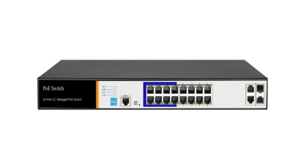
1.4 Appearance
Front Panel
Including indicators, RJ45 port, DIP switch, RST button, SFP port, CONSOLE port, as shown below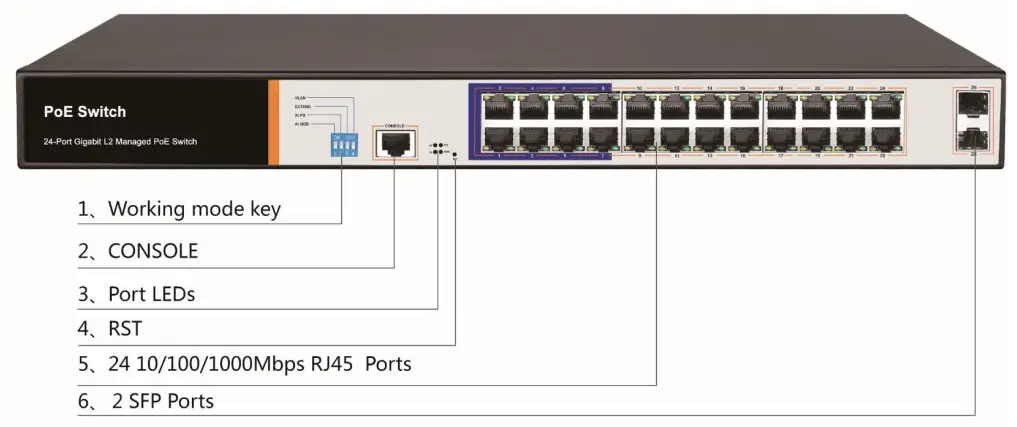
- indicator
The indicator working status is shown as the following table
The indicator working status is shown as the following table
| Indicators | Title | Color | Work status | Description |
| POWER | Power indicator | Red | Solid | Power is normal |
| Off | No power, the power switch is not turned on, power supply is abnormal | |||
| POE | POE power indicator | Yellow | Solid | The corresponding RJ45 port is connected to the powered device and the power supply is normal |
| Off | The corresponding RJ45 port is not connected to the powered device or the power supply is abnormal | |||
| LINK/ACT | Connection indicator | Green | Blinking | A valid link is established |
| Off | An invalid link is |
| established | ||||
| SYS | System indicator | Green | Blinking | System is functioning properly |
| Off | System is functioning improperly Software is damaged |
- Shortcut button
QOS: Improve video data processing capabilities and improve the monitoring of Caton and Mosaic phenomena in the network
Extend: 1-8 port rate down to 10Mbps, but the transmission distance up to 250 meters
VLAN: Isolating ports 1-8 from each other, suppress network storms effectively and improve network performance
AI power supply: Detect PD, power failure and restart dead equipment - RJ45 Port
Device with 16 10/100/1000Mbps PoE port, all port support IEEE802.3af and IEEE802.3at standard - SFP Port
Device provides two Gigabit SFP optical module expansion slots (25,26), which can be inserted into Gigabit SFP module. - RST Button
When the switch is powered on, press the button with the needle to release the device and enter the restarting state. When the SYS lamp restarts, the device restarts. When the switch is powered on, press and hold the button for more than 5s to release the button and enter the reset state. When SYS is re-lit, the device is reset successfully - Console port
Console port used to connect to computer or other terminal to manage or configure the switch.
Back Panel - Including: power socket, ground terminal

- Power socket
A 100-240VAC 50/60 Hz power receptacle for accommodating the supplied power cord - Ground terminal
Please use the grounding wire to prevent lightning. To avoid product lightning strikes and extend product life
Chapter2 Hardware connection
2.1 RJ45 port connection
Connect the RJ45 port of the switch and the corresponding network device via cables, the POE power supply function of the switch is default enabled on the downlink port of the switch, which can be used for IEEE802.3af or IEEE802.3at standards powered devices such as APs, bridges, and network cameras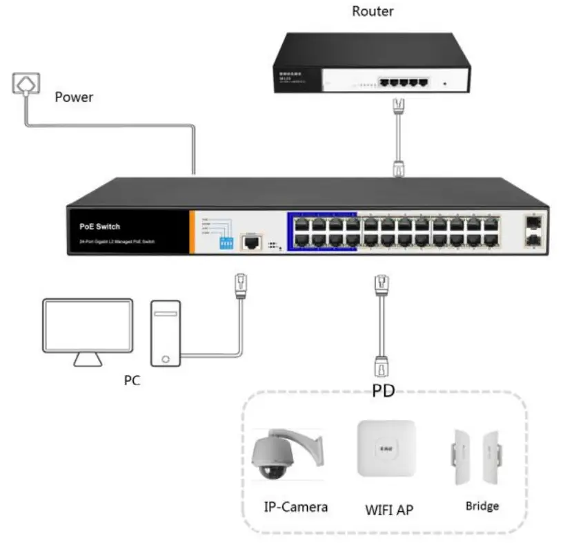
![]() Note:
Note:
When the switch connected workstations, servers, routers or other ethernet devices the cable length should be within 100 meters;
The Auto-MDI / MDIX ethernet interface is enabled by default. Category 5,the standard network cable or crossover cable can be used for Ethernet connection.
Do not connect the RJ45 port to the phone line
2.2 SFP Port connection
SFP port only support Gigabit fiber module.
Recommended use of standard SFP module products
The process of installing a fiber module on a switch is as follows:
First, grasp the optic fiber module from the side, insert it smoothly along the SFP port slot until the optic fiber module and switch are in close contact;
Second, confirm the Rx and Tx ports of the fiber module when connecting, insert one end of the fiber into the Rx and Tx ports correspondingly, ensure that the Tx and Rx ends of the interface are connected correctly and the other end of the fiber is connected to another device;
Third, please check the corresponding indicator light status after power on. If the light blinking that the link is properly connected, if the light is off , the link is failure, please check the line to confirm that the corresponding equipment is enabled.![]() Note:
Note:
DO NOT excessive bending fiber, the radius of curvature should not be lessthan 10cm;
Ensure the cleanliness of the fiber surface;
Please DO NOT look directly into the optical fiber connector with your eyes as this may cause eye injury
2.3 Check before power on
Check whether the outlet power supply meets the switch specifications;
Check the power, switches, racks and other equipment have been properly grounded;
Check whether the switch and other network devices are connected properly
2.4 Device initialization
The switch automatically initializes when the power switch is turned on.
Indicator will appear the following situation:
After the power is turned on, the power indicator remains on, the other indicator is off at this time;
After about 1 second, all lights except for the power light turn on for about 35 seconds and then turn off; when the SYS light goes flashing, the system runs normally
Port LEDs indicates the connection status of each port, indicating that the switch has started to work normally
Chapter3 Installation
3.1 Installation Precautions![]() Note: To avoid improper use of equipment damage and personal injury, please observe the following precautions
Note: To avoid improper use of equipment damage and personal injury, please observe the following precautions
- Installation safety precautions
- The power should be kept off during the installation, while wearing anti-static wrist, and to ensure well touch between anti-static wrist and skin to avoid potential safety hazard;
- The switch just works normally when it is powered by the correct power supply. Make sure that the power supply voltage matches the voltage indicated by the switch
- Before powering on the switch, make sure that the power circuit is not overloaded, which may affect the normal operation of the switch and even cause unnecessary damage
- To avoid the risk of electric shock, do not open the case while the switch is working. Do not open the case even when it is not powered
- Before cleaning the switch, unplug the switch from the power cord and do not wipe it with wet cloth. Do not wash it with liquid
- Temperature and humidity
To ensure the long-term stability working of the switch , please maintain a certain temperature and humidity environment. High or low humidity easily lead to leakage of insulation materials, deformation and even the corrosion of metal parts, the temperature is too high will accelerate the aging process of insulating materials, seriously affecting the service life of equipment. The normal operation of this series of switches and storage temperature / humidity are as follows
| Environmental description | temperature | Relative humidity |
| Working environment | 0℃~40℃ | 10%~90% RH no condensation |
| Storage environment | -40℃~70℃ | 5%~90% RH no condensation |
- Altitude
 Products with this logo are only for safe use in areas below 2000m altitude
 - Dust-proof
Dust on the switch surface will cause electrostatic adsorption, poor contact of the metal contacts. Although the device itself has done some measures in anti-static, but when the static electricity exceeds a certain intensity, it will still cause fatal damage to the electronic components on the internal circuit board.
In order to prevent static electricity from affecting the normal operation of the equipment, please note the following:
1.Regular dust, keep the indoor air clean;
2.Make sure the equipment is well grounded to ensure smooth transfer of static electricity - Electromagnetic interference
Electromagnetic interference have an impact on the device capacitance, inductance and other electronic components by capacitance, inductive coupling, impedance coupling and other conductive, in order to reduce the adverse effects caused by electromagnetic interference, please note the following:
1.Power supply system to take the necessary anti-grid interference measures;
2.Switches should be far away from high-frequency highpower, high-current devices, such as wireless transmitters;
3.If necessary, take electromagnetic shielding measures - Lightning protection
When a lightning strike occurs, a strong current will be generated in an instant cause fatal damage to electronic equipment. To achieve better lightning protection, please note the following:
1.Make sure the rack and the ground to maintain good contact;
2. Make sure the power outlet is in good contact with the earth;
3. Reasonable wiring, to avoid the internal sense ray;
4. Outdoor wiring, it is recommended to use the signal lightning protection device - Installation desk requirement
Regardless of whether the switch is installed in a rack or on another horizontal workbench, be aware of the following:
1. Make sure the rack or workbench is stable, strong, and can withstand at least 5.5Kg weight;
2. Make sure the rack has a good cooling system, or maintain good indoor ventilation;
3. Make sure the rack is well grounded, the power outlet and switch are within 1.5 meters
Prepare tools for installation
You may need to use a screwdriver during installation, electrostatic wrist strap, fiber optic cable and other tools to prepare your own
 Products with this logo are only for safe use in areas below 2000m altitude
3.2 Installation method
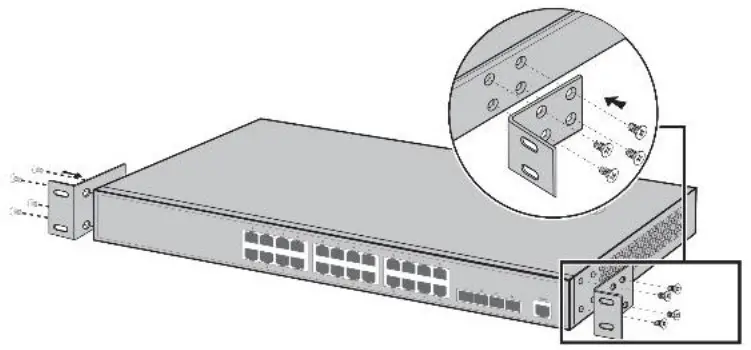
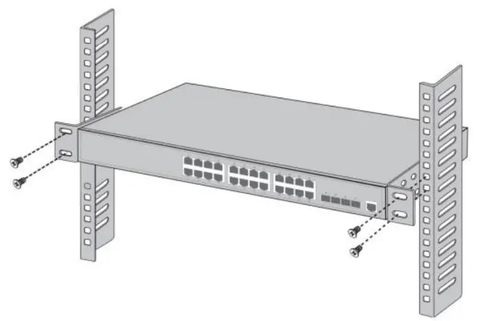
standard 19-inch frame
Device is designed according to the size of 19-inch standard rack. It can be easily installed on the rack. The specific installation steps are as follows.
- Check rack grounding and stability;
- Install the two L-brackets in the accessory on each side of the switch panel and secure with the screws provided in the accessory

- place the switch in an appropriate place in the rack and be supported by the bracket. Screw the L-shaped bracket to the guide groove fixed on both ends of the rack to ensure that the switch is stable and horizontally installed on the rack

![]() Note:
Note:
Good grounding rack is anti-static equipment, anti-leakage, lightning protection, anti-jamming important guarantee, so to ensure that the rack ground wire properly installed; Installation equipment within the rack from the bottom up, to avoid overload installation;
Avoid placing other heavy objects on switch to avoid accidents;
Ensure heat dissipation and air circulation.
3.3 Web Login
Step1. ,In the normal operation of the device, connect the computer to the switch’s RJ45 port by network cables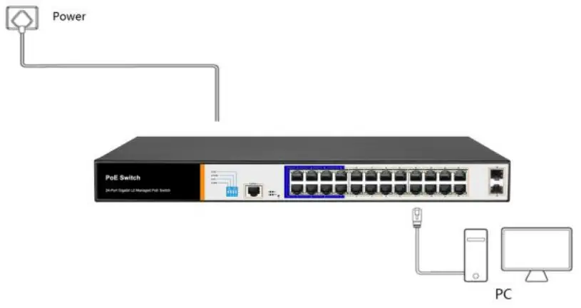 Step2. Manually changed the computer IP address to 192.168.254.X (X is 2 ~ 254), subnet mask is 255.255.255.0
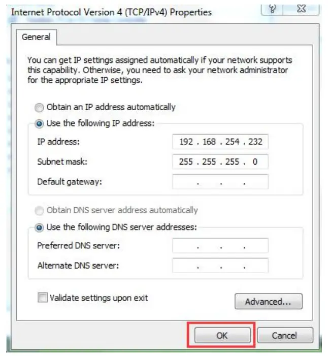 Step3. Open computer’s browser, type 192.168.254.1 in the address box, hit the Enter key
Step4. Enter the default username and password “admin” and then click Login Step5. Entered the switch web management interface successfully when you see picture as below, you can begin to configure the switch
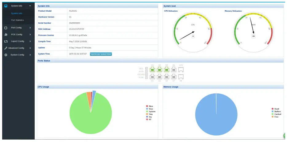
Chapter 4: Packaging and product usage suggestions
4.1 Open the package carefully check the following list
| Commodity | Quantity | Description |
| PoE switch | 1pcs | No |
| Power cord | 1pcs | Optional |
| Bracket | 2pcs | Fixed on rack mount |
| After-sale service card | 1 pcs | Used for after-ale service |
| User manual | 1pcs | Guide users to install switch |
4.2 Suggestions
- For safety reasons, non-professionals should not open the product casing;
- Pay attention to the danger of strong electricity and safe protection when the product is powered on;
- Please select the correct power adapter to supply power to the switch. Confirm whether it matches the switch requirements before use.
- Do not use the switch in a humid environment to prevent water from entering the fuselage through the casing, resulting in damage to the machine;
- Please turn on the power after the line connection is completed;
- When the product is powered on, please do not plug or unplug the cable except for special circumstances.
- Do not use the switch in places with excessive dust and electromagnetic radiation. Do not use the switch in a place with high temperature and no ventilation;
- Please do not place heavy objects on the switch to avoid accidents;
- According to the IEEE802.3AF/AT standard, the transmission distance can reach 100 meters by using Category 5 or above wires;
- When connecting a switch to multiple PDs, be careful not to exceed the maximum output power of the switch POE.
- It is recommended to use the switch indoors. It is recommended to add a waterproof box when using it outdoors.
- Considering that the network cable is too long may result in inaccurate data detection. AI Extend and AI PoE cannot be used at the same time.
Note: The pictures in the manual are for reference only, whichever is subject to the actual product.
![]()


 Managed Switch Cli User Manual")


