Sensata DHX5 IO-Link Industrial Automation Bottlenecks
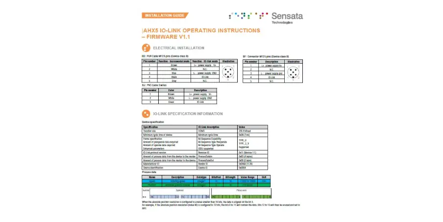
ELECTRICAL INSTALLATION
RGY : Incremental OR IO-link on Z (multiplexed)
There are two different modes, by default the encoder is in incremental mode. After an IO-link WAKEUP request, the encoder switches in IO-Link mode : the Z incre-mental signal is disabled and is configured to be the IO-link C/Q pin.
BF : Connector M12 5 pins (Device class B)
| Pin number | Function – Incremental mode | Function – IO-link mode | Illustration |
| 1 | V+ | L+: power supply |  |
| 2 | A incremental signal | N.C. | |
| 3 | GND | L-: power supply | |
| 4 | Z incremental signal | IO-Link | |
| 5 | B incremental signal | N.C. |
GP : PUR cable 8 wires
| Color | Function – Incremental mode | Function – IO-link mode |
| White | GND | L-: power supply |
| Blue | V+ | L+: power supply |
| Grey | A incremental signal | N.C. |
| Brown | B incremental signal | N.C. |
| Red | Z incremental signal | IO-Link |
| Pink | A/ incremental signal | N.C. |
| Green | B/ incremental signal | N.C. |
| Black | Z/ incremental signal | N.C. |
GM : Connector M12 8 pins
| Pin number | Function – Incremental mode | Function – IO-link mode | Illustration |
| 1 | GND | L-: power supply | 
|
| 2 | V+ | L+: power supply | |
| 3 | A incremental signal | N.C. | |
| 4 | B incremental signal | N.C. | |
| 5 | Z incremental signal | IO-Link | |
| 6 | A/ incremental signal | N.C. | |
| 7 | B/ incremental signal | N.C. | |
| 8 | Z/ incremental signal | N.C. |
G3 : PVC cable 8 wires
| Color | Function – Incremental mode | Function – IO-link mode |
| White | GND | L-: power supply |
| Brown | V+ | L+: power supply |
| Green | A incremental signal | N.C. |
| Yellow | B incremental signal | N.C. |
| Grey | Z incremental signal | IO-Link |
| Pink | A/ incremental signal | N.C. |
| Blue | B/ incremental signal | N.C. |
| Red | Z/ incremental signal | N.C. |
*Adapter M12 8 pins to M12 5 pins (IO-link device class B) reference : to define
Electronics RGZ : Incremental AND IO-link (simultaneous)
For this configuration, the incremental signals and IO-link are all available simultaneously.
Then the incremental signals can be incoherent few milliseconds after a configuration update from an IO-link command.
I6 : Connector M23 12 pins CW
| Pin number | Description | Illustration |
| 1 | L- power supply GND |  |
| 2 | L+ power supply V+ | |
| 3 | A incremental signal | |
| 4 | B incremental signal | |
| 5 | Z incremental signal | |
| 6 | A/ incremental signal | |
| 7 | B/ incremental signal | |
| 8 | Z/ incremental signal | |
| 9 | IO-Link | |
| 10 | N.C. | |
| 11 | N.C. | |
| 12 | N.C. |
IP : PUR cable 9 wires
| Color | Description |
| White | L- power supply GND |
| Blue | L+ power supply V+ |
| Grey | A incremental signal |
| Brown | B incremental signal |
| Red | Z incremental signal |
| Pink | A/ incremental signal |
| Green | B/ incremental signal |
| Black | Z/ incremental signal |
| Brown / Grey | IO-Link |
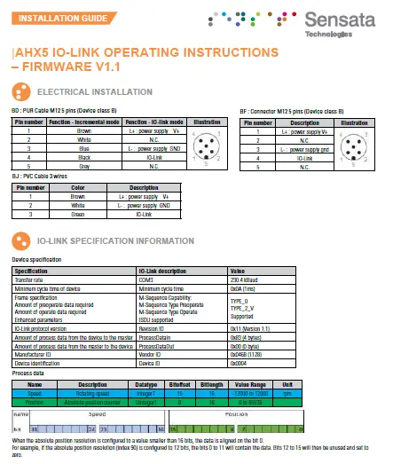
IO-LINK SPECIFICATION INFORMATION
Device specification
| Specification | IO-Link description | Value |
| Transfer rate | COM3 | 230.4 kBaud |
| Minimum cycle time of device | Minimum cycle time | 0x0A (1ms) |
| Frame specification Amount of operoperate data required Amount of operate data required Enhanced parameters | M-Sequence Capability: M-Sequence Type Operoperate M-Sequence Type Operate ISDU supported | TYPE_0 TYPE_2_V Supported |
| IO-Link protocol version | Revision ID | 0x11 (Version 1.1) |
| Amount of process data from the device to the master | Process Data In | 0x83 (4 bytes) |
| Amount of process data from the master to the device | Process Data Out | 0x00 (0 byte) |
| Manufacturer ID | Vendor ID | 0x0468 (1128) |
| Device identification | Device ID | RGY : 0x0003 RGZ : 0x0005 |
Process data
| Name | Description | Datatype | Bitoffset | Bitlength | Value Range | Unit |
| Speed | Rotating speed | IntegerT | 15 | 16 | -12000 to 12000 | rpm |
| Position | Absolute position counter | UIntegerT | 0 | 16 | 0 to 65535 |

When the absolute position resolution is configured to a value smaller than 16 bits, the data is aligned on the bit 0.
For example, if the absolute position resolution (index 90) is configured to 12 bits, the bits 0 to 11 will contain the data. Bits 12 to 15 will then be unused and set to zero.
Standard Identification data
| Index (hex) | Sub index | Name | Data type | Access | Contents | |
| RGY | RGX | |||||
| 16 (0x10) | 0 | Vendor Name | StringT | RO | BEI Sensors | |
| 17 (0x11) | 0 | Vendor Text | StringT | RO | Sensata Technologies Inc. | |
| 18 (0x12) | 0 | Product Name | StringT | RO | DHx5-RGY | DHx5-RGX |
| 19 (0x13) | 0 | Product ID | StringT | RO | Detailed reference | Detailed reference |
| 20 (0x14) | 0 | Product Text | StringT | RO | Incremental encoder configurable by IO-Link | Incremental and IO- Link absolute encoder |
| 21 (0x15) | 0 | Serial Number | StringT | RO | Unique number | |
| 22 (0x16) | 0 | Hardware Version | StringT | RO | 284v6 | |
| 23 (0x17) | 0 | Firmware Version | StringT | RO | V1.2 | |
| 24 (0x18) | 0 | Application Specific Tag | StringT | RW | *** | |
System command
| Index (hex) | Subindex | Name | Data type | Access | Value range |
| 2 (0x02) | 0 | System-Command | UIntegerT 8 | WO | 130 (0x82) : Restore factory settings |
| 131 (0x83) : Back-to-Box command |
Observation parameters
| Index (hex) | Subindex | Name | Data type | Access | Value range | Comment |
|
40 (0x28) | 0 | Process Data Input | Record | RO | Get last Process Data Input value | |
| 1 | Speed | IntegerT 16 | NA | -12000 to 12000 | Speed value. | |
| 2 | Position | UIntegerT 16 | NA | 0 to 65535 | Absolute position |
Diagnosis parameters
| Index (hex) | Subindex | Name | Data type | Access | Value range | Comment |
| 36 (0x24) |
0 | Device Status | UIntegerT 8 | RO | 0 to 4 | Device status : Device is OK [0] Maintenance required [1] Out of specification [2] Functional check [3] Failure [4] |
| 0 : normal operation | 0 | Operating hours | UIntegerT 32 | RO | 0 to 4294967295 | Number of hours with device on |
Sensata specific parameters, Observer and Maintenance access
| Index | Subindex | Name | Data type | Access | Value range | Comment |
| 70 (0x46) | 0 | Encoder Output | BooleanT | RW | False: TTL True: HTL | Set the incremental output voltage |
| 71 (0x47) | 0 | Incremental Resolution | UIntegerT 16 | RW | 1 to 10000 | Set the incremental resolution |
| 72 (0x48) | 0 | Rotation direction | BooleanT | RW | False: CW True: CCW | Set the rotation direction |
| 73 (0x49) | 0 | Set Zero Position | Button | WO | Set zero position | |
| 74 (0x4A) | 0 | Z pulse width | UIntegerT 8 | RW | 0: 90° 1: 180° 2: 270° 3: 360° | Set the zero pulse format (see table 1) |
| 80 (0x50) | 0 | Speed calculation window | UIntegerT 8 | RW | 0: 20 ms 1: 200 ms 2: 600 ms | Time between each speed data update |
| 90 (0x5A) | 0 | Absolute Position Resolution | UIntegerT 8 | RW | 1 to 16 Number of bits | Default value: 16 bits |
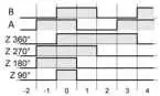
Table 1 : Z pulse width definition
Sensata specific parameters, Specialist access
| Index | Subindex | Name | Data format | Access | Value range | Comment |
| 75 (0x4B) | 0 | Enter in Factory setup mode | BooleanT | RW | 0: Encoder mode 1: Factory mode | Do not use |
| 252 (0xFC) | 0 | Test parameter 252 | UIntegerT 8 | RW | 0 : A appears 1 : A disappears 2 : B appears 3 : B disappears | Do not use For IO-link test purpose. |
Factory settings parameters
| Name | Index | Factory Setting | Comment |
| Encoder Output | 70 | 1 : HTL | Set the incremental output voltage |
| Incremental Resolution | 71 | 1024 | Set the incremental resolution |
| Rotation direction | 72 | false : CW | Set the rotation direction |
| Z pulse width | 74 | 0 : 90° | Set the zero pulse format (see table 1) |
| Enter in Factory setup mode | 75 | 0: Encoder mode | Do not use |
| Speed calculation window | 80 | 1 : 200ms | Time between each speed data update |
| Absolute Position Resolution | 90 | 16 | Resolution of the turn counter (in bits) |
| Operating-hours | 110 | 0 | Number of hours with device on |
Events
| Code | Name | Type | Comment |
| 16912 (0x4210) | Temperature issue | Warning | event appears when temperature exceeds specifications. |
| 4096 (0x1000) | General malfunction | Error | Global error on the device |
| 35840 (0x8C00) | Tech Specific app fault | Error | Technology specific application fault – Reset Device |
| 35841 (0x8C01) | Simulation active | Warning | Device in setup mode, the process data are not representing encoder position. Check operational mode |
| 35888 (0x8C30) | Process variable range under-run | Warning | Process Data uncertain. The process data send is not reliable. Do not use device process data! |
| 36000 (0x8CA0) | Sensor start error | Error | Communication error with the sensing part. Power Reset the device |
| 36001 (0x8CA1) | Download from NVM error | Error | Error while reading from permanent memory Warning parameters load error |
| 36002 (0x8CA2) | Upload to NVM error | Error | Error while writing to permanent memory Warning parameters save error |
| 35888 (0x8C30) | Test Event A | Error | Event appears by setting index 252 to value 1, Event disappears by setting index 252 to value 2 |
| 36351 (0x8DFF) | Test Event B | Error | Event appears by setting index 252 to value 3, Event disappears by setting index 252 to value 4 |
Sensata Technologies, Inc. (“Sensata”) data sheets are solely intended to assist designers (“Buyers”) who are developing systems that incorporate Sensata products (also referred to herein as “components”). Buyer understands and agrees that Buyer remains responsible for using its independent analysis, valuation, and judgment in designing Buyer’s systems and products. Sensata data sheets have been created using standard laboratory conditions and engineering practices. Sensata has not conducted any testing other than that specifically described in the published documentation for a particular data sheet. Sensata may make corrections, enhancements, improvements, and other changes to its data sheets or components without notice.
Buyers are authorized to use Sensata data sheets with the Sensata component(s) identified in each particular data sheet.
HOWEVER, NO OTHER LICENSE, EXPRESS OR IMPLIED, BY ESTOPPEL OTHERWISE TO ANY OTHER SENSATA INTELLECTUAL PROPERTY RIGHT, AND NO LICENSE TO ANY THIRD PARTY TECHNOLOGY OR INTELLECTUAL PROPERTY RIGHT, IS GRANTED HEREIN. SENSATA DATA SHEETS ARE PROVIDED “AS IS”. SENSATA MAKES NO WARRANTIES OR REPRESENTATIONS WITH REGARD TO THE DATA SHEETS OR USE OF THE DATA SHEETS, EXPRESS, IMPLIED, OR STATUTORY, INCLUDING ACCURACY OR COMPLETENESS. SENSATA DISCLAIMS ANY WARRANTY OF TITLE AND ANY IMPLIED WARRANTIES OF MERCHANTABILITY, FITNESS FOR A PARTICULAR PURPOSE, QUIET ENJOYMENT, QUIET POSSESSION, AND NON-INFRINGEMENT OF ANY THIRD PARTY INTELLECTUAL PROPERTY RIGHTS WITH REGARD TO SENSATA DATA SHEETS OR USE THEREOF.
All products are sold subject to Sensata’s terms and conditions of sale supplied at www.sensata.com SENSATA ASSUMES NO LIABILITY FOR APPLICATIONS ASSISTANCE OR THE DESIGN OF BUYERS’ PRODUCTS. BUYER ACKNOWLEDGES AND AGREES THAT IT IS SOLELY RESPONSIBLE FOR COMPLIANCE WITH ALL LEGAL, REGULATORY, AND SAFETY-RELATED REQUIREMENTS CONCERNING ITS PRODUCTS, AND ANY USE OF SENSATA COMPONENTS IN ITS APPLICATIONS, NOTWITHSTANDING ANY APPLICATIONS-RELATED INFORMATION OR SUPPORT THAT MAY BE PROVIDED BY SENSATA.
Mailing Address: Sensata Technologies, Inc., 529 Pleasant Street, Attleboro, MA 02703, USA
Copyright © 2022 Sensata Technologies, Inc.
Specification No.: 02371-001 Rev. 02/15/2022
CONTACT US
Americas
+ 1 (800) 350 2727
[email protected]
Europe, Middle East & Africa
+ 33 (3) 88 20 8080
[email protected]
Asia Pacific
[email protected]
China +86 (21) 2306 1500
Japan +81 (45) 277 7117
Korea +82 (31) 601 2004
India +91 (80) 67920890
Rest of Asia +886 (2) 27602006 ext 2808
www.sensata.com


