
Autonics TCD220050AB DPU3 Series Single-Phase-3-Phase Digital Power Controllers
Product Information
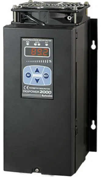
The Transparent Guide Single-Phase / 3-Phase Digital Power Controllers DPU1 / DPU3 Series are electronic devices designed to control power supply to machinery and equipment. These units are available in different models with varying rated current capacity and power supply options. The product also supports RS485 communication and remote display options. The device is equipped with fail-safe features that ensure safe operation of the machinery and equipment connected to it. The product is designed for industrial use and must be installed following the safety instructions provided in the manual.
Product Usage Instructions
Before using the DPU1 / DPU3 digital power controllers, read the user manual carefully and follow the safety instructions to ensure safe and reliable operation.
- Install the device on a panel and ground separately to prevent electric shock or fire.
- Connect the unit within the rated specifications to prevent fire or product damage.
- Use a dry cloth to clean the device and avoid using water or organic solvents which may cause electric shock or fire.
- Avoid exposing the device to flammable/explosive/corrosive gas, high humidity, direct sunlight, radiant heat, vibration, impact or salinity which may result in explosion or fire.
- Check the connections before wiring to avoid fire or product damage.
- Do not connect, repair, or inspect the unit while connected to a power source to avoid electric shock or fire.
- Do not disassemble or modify the unit to avoid electric shock or fire.
- Since leakage current still flows right after turning off the power or in the output OFF status, do not touch the load terminal to avoid electric shock or burn due to high temperature of the surface.
Follow the ordering information provided in the manual to select the specified model. Download the installation file and the manuals from the Autonics website. Use DAQMaster, the comprehensive device management program for Autonics’ products, to manage the device parameters and data.
Thank you for choosing our Autonics product. Read and understand the instruction manual and manual thoroughly before using the product. For your safety, read and follow the below safety considerations before using. For your safety, read and follow the considerations written in the instruction manual, other manuals and Autonics website. Keep this instruction manual in a place where you can find easily. The specifications, dimensions, etc. are subject to change without notice for product improvement. Some models may be discontinued without notice. Follow Autonics website for the latest information.
Safety Considerations
- Observe all ‘Safety Considerations’ for safe and proper operation to avoid hazards.
- symbol indicates caution due to special circumstances in which hazards may occur.
Warning Failure to follow instructions may result in serious injury or death.
- Fail-safe device must be installed when using the unit with machinery that may cause serious injury or substantial economic loss.(e.g. nuclear power control, medical equipment, ships, vehicles, railways, aircraft, combustion apparatus, safety equipment, crime/disaster prevention devices, etc.) Failure to follow this instruction may result in personal injury, economic loss or fire.
- Do not use the unit in the place where flammable/explosive/corrosive gas, high humidity, direct sunlight, radiant heat, vibration, impact or salinity may be present. Failure to follow this instruction may result in explosion or fire.
- Install on a device panel, and ground separately. Failure to follow this instruction may result in fire or electric shock.
- Do not connect, repair, or inspect the unit while connected to a power source. Failure to follow this instruction may result in fire or electric shock.
- Do not disassemble or modify the unit. Failure to follow this instruction may result in fire or electric shock.
- Check ‘Connections’ before wiring. Failure to follow this instruction may result in fire
Caution Failure to follow instructions may result in injury or product damage
- Use the unit within the rated specifications. Failure to follow this instruction may result in fire or product damage.
- Use a dry cloth to clean the unit, and do not use water or organic solvent. Failure to follow this instruction may result in fire or electric shock.
- Keep the product away from metal chip, dust, and wire residue which flow into the unit. Failure to follow this instruction may result in fire or product damage.
- Since leakage current still flows right after turning off the power or in the output OFF status, do not touch the load terminal. Failure to follow this instruction may result in electric shock.
- Since leakage current still flows right after turning off the power or in the output OFF status, do not touch the load terminal. Failure to follow this instruction may result in burn due to high temperature of the surface.
Cautions during Use
- Follow instructions in ‘Cautions during Use’. Otherwise, it may cause unexpected accidents.
- Use the product, after 3 sec of supplying power.
- Before use, set the mode and function according to the specification. Since changing the mode / parameter during operation may result in malfunction, set the mode and function after disconnecting load output.
- Re-supply the power to the unit after 3 sec of turning off the power. Failure to follow this instruction may result in malfunction.
- To ensure the reliability of the product, install the product on the panel or metal surface vertically to the ground.
- Install the unit in the well ventilated place.
- While supplying power to the load or right after turning off the power of the load, do not touch the body and heat sink. Failure to follow this instruction may result in a burn due to the high temperature.
- Install a power switch or circuit breaker in the easily accessible place for supplying or disconnecting the power.
- Do not wire to terminals which are not used.
- Use twisted pair wire for communication line.
- Do not use near the equipment which generates strong magnetic force or high frequency noise.
- Since inter element can be damaged when using with coil load, inductive load, etc.,
the inrush current must be under the rated load current. - To prevent product malfunction due to noise, wire power, control input,
communication, and load cables separately. - For stable operation, use shield wire for control, alarm, and communication wires.
Use a ferrite core on the shield wire to cope with EMC. - This unit may be used in the following environments.
- Indoors (in the environment condition rated in ‘Specifications’)
- Altitude max. 2,000 m
- Pollution degree 2
- Installation category III
Ordering Information
This is only for reference, the actual product does not support all combinations. For selecting the specified model, follow the Autonics website.
Control phase
- 1: Single-phase
- 3: 3-phase
Power supply
- 110 VAC
- 220 VAC
- 380 VAC
- 440 VAC
Size (rated current capacity)
| DPU1 | DPU3 | |
| A | 0 to 70 A | 0 to 50 A |
| B | 80 to 200 A | 70 to 200 A |
| C | 250 to 350 A | |
| D | 400 to 600 A | |
Rated current capacity
Number: Rated current capacity (unit: A)
Option
- R: RS485 communication
- D: Remote display
- A: Remote display + RS485 communication
- N: None
Product Components
- Product
- Bolt × 4
- Instruction manual
- Terminal × 1
Software
Download the installation file and the manuals from the Autonics website.
DAQMaster
It is the comprehensive device management program for Autonics’ products, providing parameter setting, monitoring and data management
Manual
For proper use of the product, refer to the manuals and be sure to follow the safety considerations in the manuals. Download the manuals from the Autonics website
Display
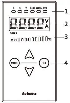
Indicator
| Indicator | Color | Descriptions |
| R / S / T | Green | [DPU3 model] Turns ON by display value of display part E.g.) R, S ON → R-S line voltage display |
| RUN | Green | Turns ON for RUN, turns OFF of STOP |
| AUTO | Green | Turns ON for AUTO, turns OFF of MANUAL |
| EVT | Red | Turns ON for Digital input ON, flashes for alarm output ON |
Display part (red)
- RUN mode: Displays depending the front display setting
- Setting mode: Displays parameter and setting value
- Unit indicator
| Indicator | Descriptions |
| V | Turns ON for voltage display |
| A | Turns ON for current display |
| V + A | Turns ON for power display, turns OFF for resistance and input value display |
Output BAR (green)
Turns on the current output (voltage / current / power) in a ratio of 0 to 100 % relative to the input.
Setting keys
| Key | Descriptions |
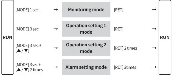
| [MODE] | To enter monitoring / operation setting 1, 2 mode and to move between parameters |
| [▲ / ▼] | To move setting modes and to set parameters. |
| [RET] | To return to RUN mode from monitoring / operation setting 1, 2 / alarm setting mode |
Unit Descriptions
Configurations may vary by model depending on supported specifications.
DPU1 Series
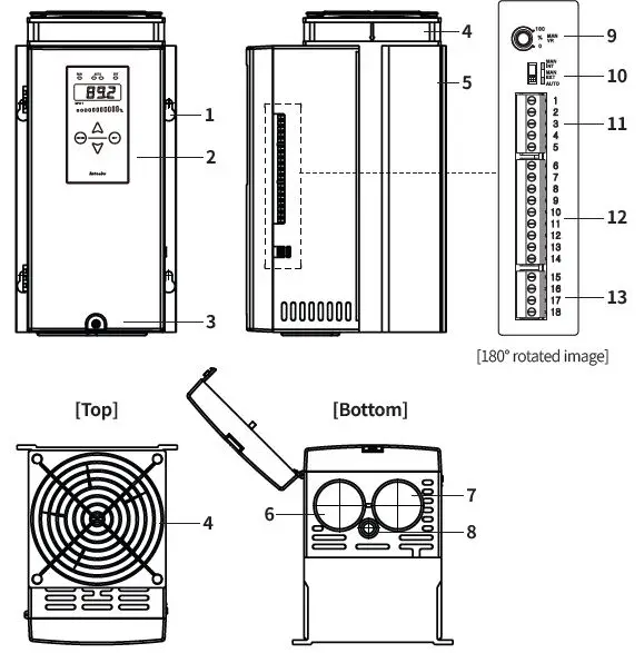
DPU3 Series
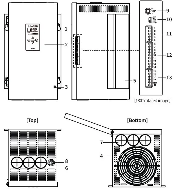
- Mounting holes
- Display
- Case screw
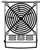
- Cooling fan 01)
- Heatsink
- Load wiring input hole
- Load wiring output hole
- Ground wiring hole
- Internal adjuster
- AUTO / MANUAL select switch
- Control input (voltage / current) connector
- Control input (contact) / RS485 communication connector
- DPU1: alarm output connector
- DPU3: control power (FAN) / alarm output connector
DPU1 Series 25 / 40 / 50 A models do not have attached a Fan.
Specifications
| Series | DPU1 | DPU3 |
| Control phase | Single-phase | 3-phase |
| Rated frequency | 50 / 60 Hz (auto recognition), allowable frequency range: ± 2 Hz | |
| Display method | 4 digit 7 segment, Output BAR | |
| Indicators | Operation / manual control indicator (green) DI, alarm / unit (V, A) indicator (red) | R, S, T indicator (green) Operation / manual control indicator (green) DI, alarm / unit (V, A) indicator (red) |
|
Auto control input | • Current 01): 4 – 20 mA, 0 – 20 mA • Voltage 02): 0 – 5 VDCᜡ, 1 – 5 VDCᜡ, 0 – 10 VDCᜡ • Contact (non-voltage): ON / OFF • Contact (voltage): 0 / 12 VDCᜡ (24 VDCᜡ) • Communication: RS485 | |
| Manual control input | Internal adjuster (10 kΩ), external adjuster (3 to 10 kΩ, ≥ 2 W) | |
| Digital input (DI) | AUTO / MAN selectable, RUN / STOP selectable, RESET, HOLD, Setting Point 1 to 6 | |
| Display content | Control input, load voltage, load current, load power, load resistance, power supply frequency | |
| Min. display output | Min. 2.5 % of rated voltage / current | |
| Approval | ᜢ, ᜧ, ᜫ | |
| SCCR Rating | 80 kA (UL certification) | |
- Input impedance = 100 Ω
- Input impedance = 25 Ω
| Control method | Phase control | Cycle control | ON / OFF control |
| Control mode | Normal / constant current feedback / constant voltage feedback / constant power feedback | Fixed cycle / variable cycle 01) |
– |
| Applied load | Resistance / inductive load | Resistance load | Resistance load |
| Output range | 0 to 98 % | 0 to 100 % | 0 to 100 % |
|
Output accuracy of phase control | • Normal : Within ± 10 % F.S. of rated load voltage • Constant current feedback: Within ± 3 % F.S. of rated load current (within variable 1 to 10 times of rated resistance) • Constant voltage feedback: Within ± 3 % F.S. of rated load voltage (within variable ± 10 % F.S. of rated voltage) • Constant power feedback: Within ± 3 % F.S. of rated load power (within variable ±10% F.S. of rated power and within variable 1 to 10 times of rated resistance) | ||
DPU1 only
| Series | DPU1 | DPU3 |
| Power supply | 110 / 220 / 380 / 440 VACᜠ model | 110 / 220 / 380 / 440 VACᜠ model (fan and control power 220 VACᜠ 50 / 60 Hz separately) |
| Allowable voltage range | 90 to 110 % of power supply | 85 to 115 % of power supply |
| Min. load current | 1 A | |
| Power consumption | ≤ 40 W (control power) | ≤ 60 W (control power) |
| Insulation resistance | ≥ 200 MΩ (500 VDCᜡ megger) | |
| Dielectric strength | Between input terminal and power terminal: 2000 VACᜠ 50 / 60 Hz for 1 min | |
| Vibration | 0.75 mm double amplitude at frequency of 5 to 55 Hz (for 1 min) in each X, Y, Z direction for 2 hours | |
| Noise immunity | ±2 kV square wave noise (pulse width: 1 ㎲) by the noise simulator | |
| Ambient temp. | -10 to 50 ℃, storage: -20 to 80 ℃ (no freezing or condensation) | |
| Ambient humidity | 5 to 90 %RH, storage: 5 to 90 %RH (no freezing or condensation) | |
| Unit weight (packaged) | DPU1 | DPU3 |
| A | ≈ 3.0 kg (≈ 3.2 kg) | ≈ 6.5 kg (≈ 7.6 kg) |
| B | ≈ 3.0 kg (≈ 5.6 kg) | ≈ 11.5 kg (≈ 13.0 kg) |
| C | ≈ 11.0 kg (≈ 12.1 kg) | ≈ 20.0 kg (≈ 21.1 kg) |
| D | ≈ 11.0 kg (≈ 19.3 kg) | ≈ 30.8 kg (≈ 35.7 kg) |
Communication Interface
RS485
| Comm. protocol | Modbus RTU |
| Application standard | Compliance with EIA RS485 |
| Max. connection | 31-unit (address: 01 to 64) |
| Comm. synchronous method | Asynchronous |
| Comm. method | 2-wire half duplex |
| Comm. distance | ≤ 800 m |
| Comm. speed | 4,800 / 9,600 / 19,200 / 38,400 (default) bps |
| Comm. response time | 5 to 99 ms |
| Data bit | 8-bit (fixed) |
| Parity bit | Even (fixed) |
| Stop bit | 1-bit (fixed) |
Initial Display When Power is ON
- When power is supplied, after all display will flash for 1 sec, device version > rated voltage > rated current are displayed sequentially. After this, enter into RUN mode.
- Example of DPU 2A-050 model,
| 1. Display part | 2. Device version | 3. Rated voltage | 4. Rated current | 5. RUN mode | |
| DPU1 | )))0 | DP20 | 220 | 50 | 10)3 |
| DPU3 | )))0 | DP30 | 220 | 50 | 10)3 |
Alarm
- Parameter setting is available to set alarm delay time, alarm channel, etc.
- For details on parameter setting, refer to the product manual
| Alarm | Display | Operation | Alarm release 01) |
| Overcurrent | O-C | Stop (SCR OFF) |
• Re-supply power. • Press [RET]. 02) • Switch to STOP mode |
| Overvoltage | O-V | ||
| Fuse break 03) | FUSE | • DPU1: Stop (SCR OFF) • DPU3: when 1-phase break, it maintains output when 2-phase break, it stops output. | |
| Heatsink over heat | TEMP | Stop (SCR OFF) | |
| SCR error 03) | SCR | ||
| Heater break | H-BK | Continues operation | Automatically released within the setting range |
- If the alarm occurrence condition is not removed, the alarm is re-occur even if the alarm release method is applied.
- The power is reapplied.
- If the alarm is not released after power is applied again, replace the fuse or check whether the SCR element is abnormal.
Replacement of Fuse
- To prevent accident, replace a fuse every two years.
- Must turn off the power before removing the fuse.
- If using a fuse not supplied by Autonics, the performance of the product is not guaranteed. When replacing the fuse, use a fuse of the recommended specification.
Fuse position
After loosening the case screws, there is a fuse on the side of the product.
[DPU1]
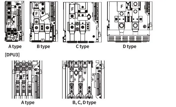
Among R, S, T inputs, R and S have a built-in fuse, but T does not have an internal fuse. If a fuse is required, install a fuse of the following or equivalent performance outside the product separately.
| Device size | Fuse fixed bolt | |
| DPU1 | DPU3 | |
| A | M5 | M6 |
| B | M8 | |
| C | M8 | |
| D | M12 | |
Fuse recommended specifications
Rated short circuit test is evaluated as a recommended fuse
| Rated load current [A] | DPU1 | DPU3 | ||
| Rec. fuse | Manufacturer | Rec. fuse | Manufacturer | |
| 25 | 50FE | 50FE | ||
| 40 | 63ET | 63ET | ||
| BUSSMANN | ||||
| 50 | 80ET | 80ET | ||
| 70 | 100FE | 170M1367 | ||
| 80 | 660GH-125 | 170M1368 | ||
| 100 | 660GH-160 | 170M1369 | ||
| 120 | 660GH-160 | 170M1369 | ||
| HINODE | ||||
| 150 | 660GH-200 | 170M1370 | BUSSMANN | |
| 180 | 660GH-250 | 170M1370 | ||
| 200 | 660GH-250 | 170M1372 | ||
| 250 | 170M2620 | 170M2620 | ||
| BUSSMANN | ||||
| 350 | 170M2621 | 170M2621 | ||
| 400 | A60X500-4(TA) | 170M3471 | ||
| 500 | A60X600-4(TA) | MERSEN | 170M4466 | |
| 600 | A60X600-4(TA) | 170M4466 | ||
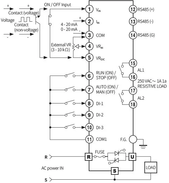
Connections
Terminal configuration by model may differ depending on the supported spec.
DPU1 Series
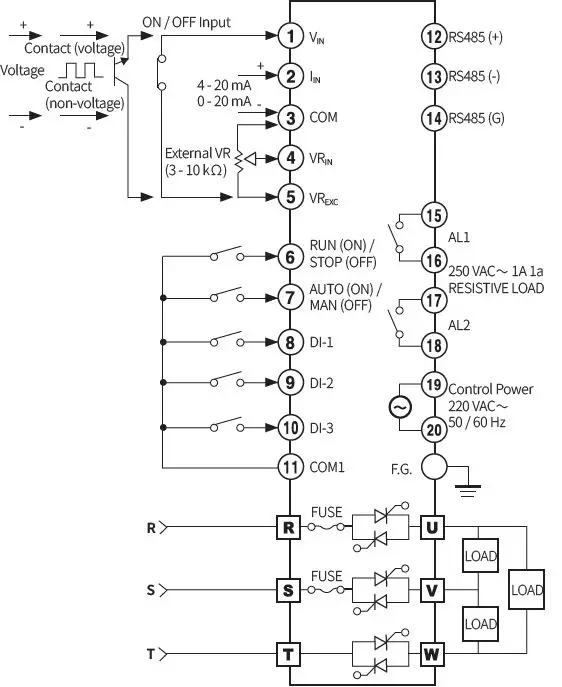
DPU3 Series
Suitable specification
The following connectors can be used with equivalent or substitute
| Connector configuration | |||
| Connector type | Manufacturer | ||
| DPU1 | DPU3 | ||
| Control input (current, voltage) | TS 05 515B | TS 05 515B | |
| Alarm output / control power (DPU3) | TS 04 515B | TS 06 515B | ANYTEK |
| Control input (contact) / RS485 communication | TS 09 515B | TS 09 515B | |
Cautions during Wiring
- DI input switch: For low current, ON resistance: 20Ω or less (including wiring resistance).
- Do not arbitrarily replace the display – main body connector of the remote display model.
- For crimp terminals of load input/output connectors, use the following UL approved terminals. Be sure to use crimp terminals with an insulating sleeve (tube).
| Device size | DPU1/3 wire thickness | Crimp terminal spec. | Bolt tightening torque |
| A | ≥ 25 mm2 | 25-S6 (1) | 5.6 to 6.0 Nm |
| B | ≥ 95 mm2 | 95-8 (1) | 13.6 to 14.5 Nm |
| C | ≥ 2 × 70 mm2 | 70-8 (2) | 13.6 to 14.5 Nm |
| D | ≥ 2 × 185 mm2 | 185-12 (2) | 47.0 to 50.0 Nm |
Cautions during Installation
High Temperature Caution
While supplying power to the load or right after turning off the power of the load, do not touch the body and heatsink. Failure to follow this instruction may result in a burn due to the high temperature
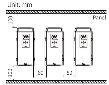
Mount space
When installing multiple power controllers, keep space between power controllers for heat radiation.
- Horizontal: ≥ 80 mm
- vertical: ≥ 100 mm
Dimensions
Unit: mm, For the detailed drawings, follow the Autonics website.
DPU1 Series
The figure is based on the B size.
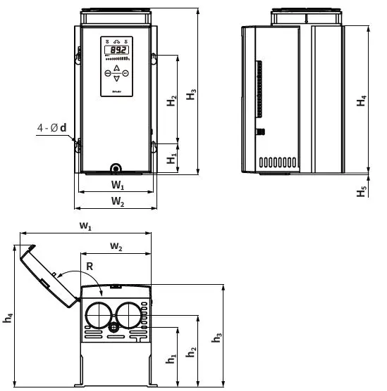
| Size | d | R | W1 | W2 | H1 | H2 | H3 | H4 | H5 | w1 | w2 | h1 | h2 | h3 | h4 |
| A | 6 | 135° | 82 | 97 | 40 | 150 | 233 01) | 230 | 3 | 154 | 80 | 90 | 110 | 170.3 | 209.5 |
| B | 6 | 135° | 127 | 140 | 50 | 150 | 283 | 250 | 3 | 222 | 120 | 101.5 | 121.5 | 174 | 241.5 |
| C | 7 | 160° | 193 | 213 | 50 | 200 | 342 | 300 | 4 | 368 | 185.6 | 131 | 132 | 179 | 244 |
| D | 7 | 160° | 261 | 278 | 40 | 200 | 422 | 380 | 4 | 497 | 252.7 | 138 | 156 | 212 | 296 |
Rated current capacity 70 A model: 263
DPU3 Series
The figure is based on the C size
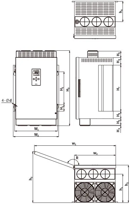
| Size | d | W1 | W2 | H1 | H2 | H3 | H4 | H5 | H6 | H7 | H8 | H9 |
| A | 6 | 127 | 140 | 63.5 | 150 | 309 | H4 + H5 = 29 | H6 + H7 + H8 = 277 | – | |||
| B | 7 | 195 | 213 | 40 | 200 | 367 | 3.5 | – | 40 | 280 | 40 | – |
| C | 7 | 261 | 278 | 40 | 200 | 457 | 3.3 | 40 | 45 | 280 | 45 | 40 |
| D | 8.5 | 405 | 427 | 66.5 | 330 | 536 | 4 | 32.5 | H6 + H7 + H8 + H9 = 495.5 | |||
| Size | R | w1 | w2 | h1 | h2 | h3 | h4 |
| A | 160° | 244 | 122.6 | 138 | 200 | 239 | 116 |
| B | 160° | 366 | 185.6 | 176 | 217 | 278 | 126 |
| C | 160° | 497 | 252.6 | 173 | 227.5 | 311 | 125 |
| D | 160° | 755 | 385.6 | 204.5 | 275.5 | 405 | 204.5 |
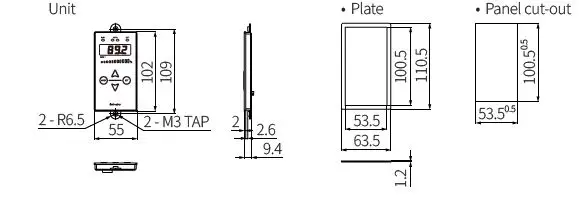
Remote display
Unit
Mode Setting
18, Bansong-ro 513Beon-gil, Haeundae-gu, Busan, Republic of Korea, 48002 www.autonics.com | +82-2-2048-1577 | [email protected]


