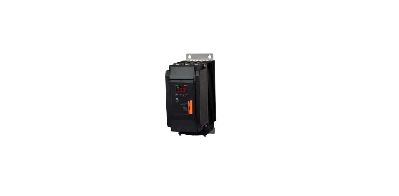
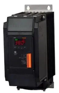
Autonics SPR3 Series 3-Phase Slim Power Controller
Safety Considerations
Observe all ‘Safety Considerations’ for safe and proper operation to avoid hazards.
Warning Failure to follow instructions may result in serious injury or death.
- Fail-safe device must be installed when using the unit with machinery that may cause serious injury or substantial economic loss.(e.g. nuclear power control, medical equipment, ships, vehicles, railways, aircraft, combustion apparatus, safety equipment, crime / disaster prevention devices, etc.) Failure to follow this instruction may result in personal injury, economic loss or fire. Do not use the unit in the place where flammable / explosive / corrosive gas, high humidity, direct sunlight, radiant heat, vibration, impact or salinity may be present.
- Failure to follow this instruction may result in explosion or fire.
- Install on the device panel, and ground to the bolt for grounding separately. Failure to follow this instruction may result in fire or electric shock.
- Do not connect, repair, or inspect the unit while connected to a power source. Failure to follow this instruction may result in fire or electric shock.
- Check ‘Connections’ before wiring. Failure to follow this instruction may result in fire.
- Do not disassemble or modify the unit. Failure to follow this instruction may result in fire or electric shock.
Caution Failure to follow instructions may result in injury or product damage.
- Use the unit within the rated specifications. Failure to follow this instruction may result in fire or product damage.
- Use a dry cloth to clean the unit, and do not use water or organic solvent. Failure to follow this instruction may result in fire or electric shock.
- Keep the product away from metal chip, dust, and wire residue which flow into the unit. Failure to follow this instruction may result in fire or product damage.
- Since leakage current still flows right after turning off the power or in the output OFF status, do not touch the load terminal. Failure to follow this instruction may result in electric shock.
Cautions during Use
Follow instructions in ‘Cautions during Use’. Otherwise, it may cause unexpected accidents.
- Use the product, after 3 sec of supplying power. Before use, set the mode and function according to the specification. Especially, be cautious that the product does not operate when OUT ADJ. is set to 0%. Since changing the mode / parameter during operation may result in malfunction, set the mode and function after disconnecting load output.
- Re-supply the power to the unit after the unit is discharged completely. Failure to follow this instruction may result in malfunction.
- To ensure the reliability of the product, install the product on the panel or metal surface vertically to the ground. Install the unit in the well ventilated place.
- While supplying power to the load or right after turning off the power of the load, do not touch the body and heat sink. Failure to follow this instruction may result in a burn due to the high temperature.
- Install a power switch or circuit breaker in the easily accessible place for supplying or disconnecting the power.
- Do not wire to terminals which are not used.
- Since inter element can be damaged when using with coil load, inductive load, etc.,
- Do not use near the equipment which generates strong magnetic force or high frequency noise.
- This unit may be used in the following environments.
- Indoors (in the environment condition rated in ‘Specifications’)
- Altitude max. 2,000 m
- Pollution degree 2
- Installation category III
Product Components
- Product ×1
- 11-pin connector ×1
- Insulating barrier ×4
Manual
For the detailed information about communication, etc., please refer to the manuals, and be sure to follow cautions written in the technical descriptions.
Visit Autonics website to download manuals.
DAQMaster
- DAQMaster is comprehensive device management program. It is available for parameter setting, monitoring.
- Visit Autonics website to download the manual and the program.
Ordering Information
This is only for reference. For selecting the specified model, follow the Autonics website.
Rated load voltage
- 110 VAC
- 220 VAC
- 380 VAC
- 440 VAC
Rated load current
Number: Rated load current (unit: A)
Option output
- N: Alarm output
- T: Alarm output + RS485 comm. output
Feedback control
- N: Normal control
- F: Normal, feedback control (constant
Fuse
- N: None
- F: Supports fuse
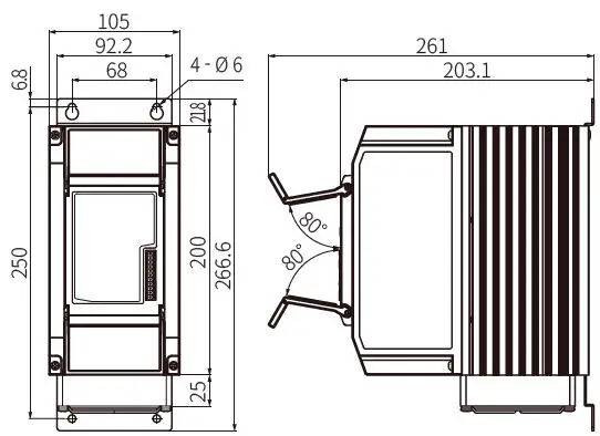
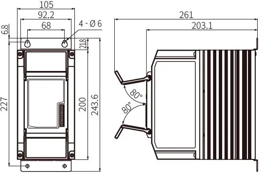
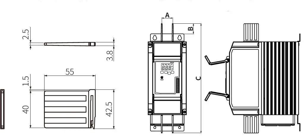
Dimensions
Unit: mm, For the detailed drawings, follow the Autonics website.
- Rated load current 25 / 35 / 50 A

- Rated load current 70 A

- Rated load current 100 / 150 A

Insulating Barrier
It is recommended to use the included interphase barriers for insulation between phases and reduce influence from conductive material.
- Unit: mm, For the detailed drawings, follow the Autonics website.
- With the insulating barrier A
| Rated load current | A | B | C |
| 25 / 35 / 50 A | 30 | 28.2 | 300 |
| 70 A | 30 | 28.2 | 300 |
| 100 / 150 A | 40.5 | 50 | 370 |
Cautions during Installation
High Temperature Caution
While supplying power to the load or right after turning off the power of the load, do not touch the body and heatsink. Failure to follow this instruction may result in a burn due to the high temperature.
Mount space

When installing multiple power controllers, keep space between power controllers for heat radiation. Horizontal: ≥ 50 mm, vertical: ≥ 100 mm
Unit Descriptions
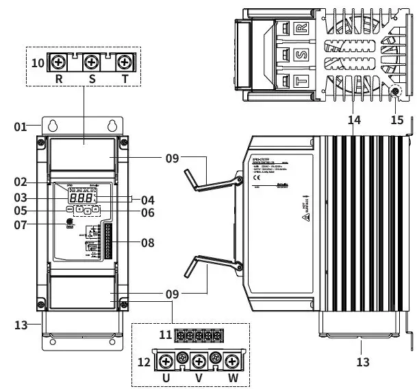
- Bracket [except rated load current 100 / 150 A model]
- Indicator
- Indicator/Function
- RUN/Operation indicator (green)/Turns on in the RUN mode.
- MAN/Manual control indicator (green)/Turns on when adjusting load output in the manual control mode.
- ALM/Alarm indicator (red)/Flashes in alarming status.
- OUT/Output indicator (red)/Turns on when load control outputs.
- Display part RUN mode: Displays depending the front display setting Setting mode: Displays parameter and setting value
- Unit indicator (V, A) Dependent on the display setting.
- [MODE] key Enters parameter group, returns to RUN mode, moves parameters, and saves the setting value.
- [◀], [▼], [▲] key Enters SV setting mode and move digits.
- Output limit adjuster (OUT ADJ) Limits output from 0 to 100%.
- Control input / comm. output terminal (11-pin connector terminal)
- Terminal protection cover
- R, S, T load input terminal
- Alarm output / power input terminal
- U, V, W load output terminal
- Cooling fan [Rated load current 70 / 100 / 150 A model]
- Heatsink Rated load current 100 / 150 A models have left / right mounting holes.
- Bolt for grounding (M4)
Specifications
| Model | SPR3-1▭ | SPR3-2▭ | SPR3-3▭ | SPR3-4▭ |
| Control phase | 3-Phase | |||
| Rated load voltage | 110 VACᜠ 50 / 60 Hz | 220 VACᜠ 50 / 60 Hz | 380 VACᜠ 50 / 60 Hz | 440 VACᜠ 50 / 60 Hz |
| Rated load current | Rated load current 25 / 35 / 50 / 70 / 100 / 150 A | |||
| Display method | 3 digit 7segment LED | |||
| Indicators | Operation / manual control indicator (green) Alarm / output / unit (V, A) indicator (red) | |||
| Auto control input | DC 4 – 20 mA, 1 – 5 VDCᜡ, ON / OFF contact (non-voltage input), pulse voltage (5 – 12 VDCᜡ) | |||
| Manual control input | External adjuster (10 kΩ), internal adjuster (output limit) | |||
| Digital input (DI) | RUN / STOP selectable, AUTO / MAN selectable, RESET | |||
| Alarm output | 250 VACᜠ 3 A, 30 VDCᜡ 3 A, 1c resistance load | |||
| RS485 comm. output | Modbus RTU method | |||
| Cooling method | Rated load current 25 / 35 / 50 A: natural cooling Rated load current 70 / 100 / 150 A: forced air cooling (with cooling fan) | |||
| Unit weight (packaged) | Rated load current 25 / 35 / 50 A: ≈ 4.1 kg (≈ 4.9 kg) Rated load current 70 A: ≈ 4.2 kg (≈ 5 kg) Rated load current 100 / 150 A: ≈ 8.7 kg (≈ 9.7 kg) | |||
| Approval | ||||
| Control method | Phase control | Cycle control | ON/OFF control |
| Control mode | Normal / constant current feedback / constant voltage feedback / constant power feedback | Fixed cycle | – |
| Applied load | Resistance load, inductive load | Resistance load | Resistance load, inductive load |
| Output range | 0 to 98% | 0 to 100% | 0 / 100% |
| Phase control output accuracy | Normal control: within ± 10% F.S. of rated load voltage Constant current feedback control: within ± 3% F.S. of rated load current Constant voltage feedback control: within ± 3% F.S. of rated load voltage Constant power feedback control: within ± 3% F.S. of rated load power | ||
| Power supply | 100 – 240 VACᜠ ±10% 50 / 60 Hz |
| Min. load current | 1 A |
| Power consumption | Rated load current 25 / 35 / 50 A: ≤ 14 VA Rated load current 70 A: ≤ 22 VA Rated load current 100 / 150 A: ≤ 32 VA |
| Insulation resistance | ≥ 200 MΩ (500 VDCᜡ megger) |
| Dielectric strength | 2,000 VACᜠ 50 / 60 Hz for 1 min (between input and power terminal) |
| Output leakage currents | ≤ 10 mArms |
| Noise immunity | ±2 kV the square wave noise (pulse width: 1 ㎲) by the noise simulator |
| Memory retention | ≈ 10 years (when using non-volatile semiconductor memory type) |
| Vibration | 0.75mm amplitude at frequency of 5 to 55Hz in each X, Y, Z direction for 2 hours |
| Vibration (malfunction) | 0.5mm amplitude at frequency of 5 to 55Hz in each X, Y, Z direction for 10 min |
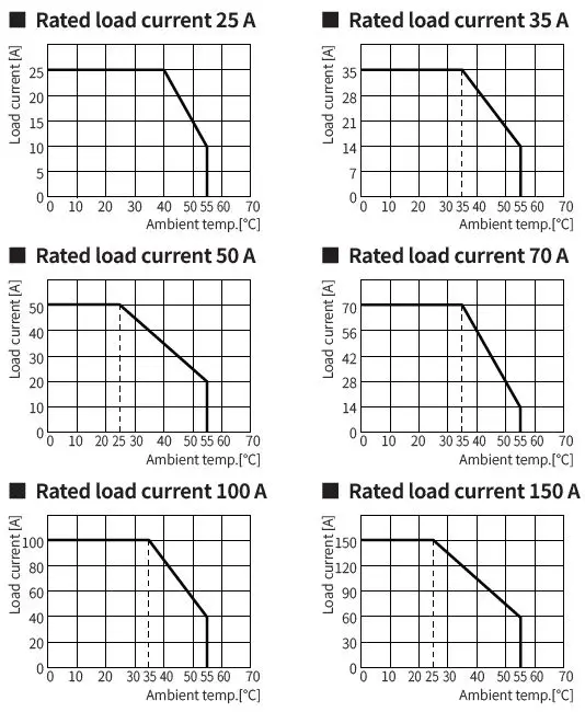
| Ambient temp. | -10 to 55 ℃, storage: -20 to 80 ℃ (rated at no freezing or condensation) |
| Ambient humi. | 35 to 85%RH, storage: 35 to 85%RH (rated at no freezing or condensation) |
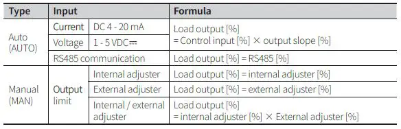
Load Output Formula
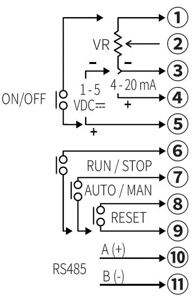
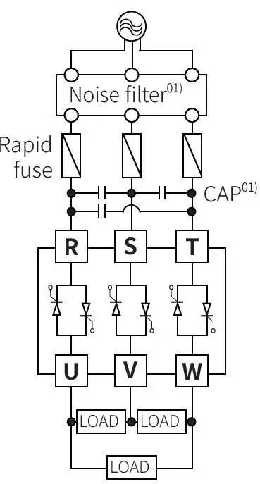
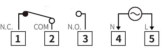
Connections
Terminal configuration by model may differ depending on the supported spec.
Control input / comm. output terminal (11-pin connector)
Load input / output terminal
Alarm output / power input terminal
Cautions during Wiring
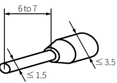
Control input / comm. output terminal (11-pin connector)
Unit: mm, Use penhole terminals of size specified below.
Alarm output / power input & R, S, U load output terminal
Unit: mm, Use crimp terminals of size specified below.
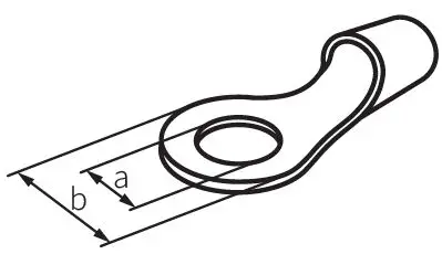
| Rated load current | Spec. | Alarm output / power input | Load input / output |
| 25 / 35 / 50 / 70 A | a | ≥ 3.0 | ≥ 6.0 |
| b | ≤ 6.0 | ≤ 16.0 | |
| 100 / 150 A | a | ≥ 3.0 | ≥ 8.0 |
| b | ≤ 6.0 | ≤ 26.0 |
Cable / screw / tightening torque spec. is different depending on the load current. Be sure to the below before connection.
| Rated load current | Spec. | Alarm output / power input | Load input / output |
|
25 / 35 / 50 / 70 A | Cable | AWG 18 to 14 | AWG 13 to 4 |
| Screw | M3 | M6 | |
| Tightening torque | 0.5 N m | 5.5 to 6.0 N m | |
|
100 / 150 A | Cable | AWG 18 to 14 | AWG 4 to 2 / 0 |
| Screw | M3 | M8 | |
| Tightening torque | 0.5 N m | 6.5 to 7.0 N m |
Alarm
- Supported alarms are different depending on the model.
- When several alarms occur at same time, the highest priority error is displayed based on priority.
| Priority | Type | Display | Operation | Alarm release | Model | |
| Alarm | Output | |||||
| 1 | SCR error | SCR | • Error display flashes. • Alarm indicator (ALM) flashes. • Alarm output turns ON |
Output stops. (SCR OFF) | • Re-supply power. • RESET input • Switch to stop (STOP) mode. | Feedback control |
| 2 | Over current | O-C | Feedback control | |||
| 4 | Heatsink over heat | TEM | Normal / Feedback control | |||
| 5 | Over voltage | O-V | Feedback control | |||
| 3 | Fuse break | FUS | Automatically cleared when returning within the setting range | Normal / Feedback control | ||
| 6 | Heater break | H-B | Normal operation | Feedback control | ||
- SCR error alarm Even though output is 0%, if the current of 10% or more of the rated load current flows for over 3 sec continuously, SCR error alarm occurs.
- Over current alarm This function protects the load from over current. If the current flows over the P2-7 over current alarm value and P2-8 over current alarm delay time, over current alarm occurs.
- Heatsink over heat alarm When the temperature of a heatsink is over 85 ℃, heatsink over heat alarm occurs.
- Over voltage alarm This function protects the load from over voltage. If the current flows over the P2-9 over voltage alarm value and P2-10 over voltage alarm delay time, over voltage alarm occurs.
- Fuse break alarm When breaking fuse, not suppling load power, breaking load (single load), fuse brake alarm occurs. In the case of normal control model, real-time fuse break alarm is not available during output, and fuse break alarm operates at 0% output such as RESET.
- Heater break alarm Comparing the full load resistance value and the current load resistance value, if the current load resistivity is maintained under the P2-12 heater break alarm value for over 3 sec continuously, heater break alarm occurs. This alarm operates when control output is over 10% and load current is over 10% of the rated current. Output does not stop and operates normally.
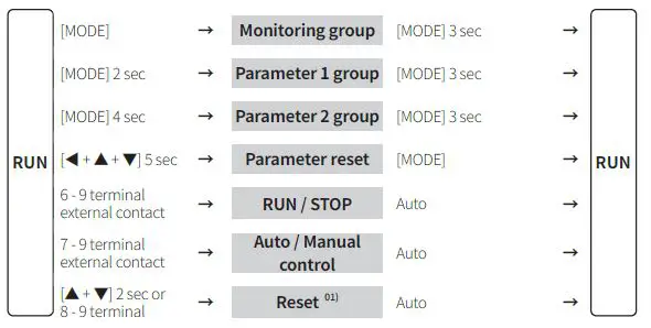
Mode Setting
Parameter Setting
- Some parameters are activated / deactivated depending on the model or setting of other parameters. Refer to the description of each parameter.
- If any key is not entered for 30 sec in each parameter, it returns to RUN mode.
- [MODE] key: Saves current setting value and moves to the next parameter. [◀ ] key: Changes setting digits.
Monitoring group
| Parameter | Display | Display range | |
| M1-1 | Monitoring value | IN | 0 to 100% |
| M1-2 U-V line load voltage value | U-V | [Feedback control model] 0 to rated voltage range, V | |
| M1-3 V-W line load voltage value | V-W | ||
| M1-4 W-U line load voltage value | W-U | ||
| M1-5 U-phase load current value | U-A | [Feedback control model] 0 to rated current range, A | |
| M1-6 V-phase load current value | V-A | ||
| M1-7 W-phase load current value | W-A | ||
| M1-8 | Load power value | L-W | [Feedback control model] 0 to rated Power range, kW |
|
M1-9 Resistance value percentage |
L-R | [Feedback control model] 0 to 100% • Displays the present resistance as percentage compared to the set resistance of full load auto recognition. | |
| M1-10 | Heatsink temp. | TMP | 0 to 100 ℃ |
| M1-11 Power supply frequency | FRQ | 50, 60 Hz | |
Parameter 1 group
| Parameter | Display | Default | Setting range | |
| P1-1 | SOFT START time | S-T | 3 | 0 to 100 sec |
| P1-2 | SOFT UP time | U-T | 3 | |
| P1-3 | SOFT DOWN time | D-T | 3 | |
| P1-4 | Output low-limit value | L-L | 0 | 0 ≤ L-L ≤ H-L ≤ 100 % |
| P1-5 | Output high-limit value | H-L | 100 | |
| P1-6 | Output slope 01) |
SLP |
100 | 0 to 100% • In case of auto control (AUTO), set the output slop limit proportional to control input for limit load power. |
Parameter 2 group
| Parameter | Display | Default | Setting range | |
|
P2-1 |
Control input 01) |
INT |
420 | 420: DC 4 – 20 mA 1-5: 1 – 5 VDCᜡ 512: 5 – 12 VDCᜡ ONF: ON / OFF contact COM: RS485 communication |
|
P2-2 |
Control method |
C-M |
PA | *[Feedback control model] |
| P2-3 | Manual control (MAN) output limit method 01) | MAN | I_R | I_R: Internal adjuster E_R: External adjuster E_I: Internal / external adjuster |
| P2-4 | Input correction 01) | INB | )0 | -99 to 99% |
| P2-5 | Input slope correction 01) | SPN | )0 | |
|
P2-6 |
Front display |
DIS |
IN | *[Feedback control model] IN: Resistance and input U-V*: U-V line load voltage V-W*: V-W line load voltage W-U*: W-U line load voltage U-A*: U-phase load current V-A*: V-phase load current W-A*: W-phase load current L-W*: Load power |
| P2-7 | Over current alarm value | OCV | 120 | [Feedback control model] 0 to 120% |
| P2-8 | Over current alarm delay time | OCT | 5 | [Feedback control model] 0 to 100 sec |
| P2-9 | Over voltage alarm value | OVV | 120 | [Feedback control model] 0 to 120% |
| P2-10 | Over voltage alarm delay time | OVT | 5 | [Feedback control model] 0 to 100 sec |
|
P2-11 |
Load resistance value auto recognition |
F-L |
OFF | [Feedback control model] OFF, ON • It executes 100% control output for 3 sec and the load resistance value recognized automatically as the initial set when the function is ON. |
| P2-12 | Heater break alarm value | HBV | 10 | [Feedback control model] 10 to 100%, OFF |
| P2-13 | Comm. address | ADR | 01 | [RS485 communication output model] 01 to 99 |
| P2-14 | Comm. speed | BPS | 96 | [RS485 communication output model] 24, 48, 96, 192, 384 bps (× 100) |
| P2-15 | Comm. parity bit | PRT | NON | [RS485 communication output model] NON, EVE, ODD |
| P2-16 | Comm. stop bit | STP | 2 | [RS485 communication output model] 1, 2 bit |
| P2-17 | Comm. response time | RwT | 20 | [RS485 communication output model] 5 to 99 ms |
| P2-18 | Comm. write | CmW | EnA | [RS485 communication output model] EN.A: Enable, DS.A: Disable |
| P2-19 | Lock | LOC | OFF | OFF LC1: Locks parameter 1 group LC2: Locks parameter 2 group |
| P2-20 | Parameter reset | INI | NO | NO, YES |
| Type | Control input | Display | Input correction | Input slope correction | Output slope | Monitoring value | ||
|
Auto control (AUTO) | Current | DC 4 – 20 mA |
INT | 420 | ○ | ○ | ○ |
The last control input value 0 to 100% |
| Voltage | 1 – 5 VDCᜡ | 1-5 | ○ | ○ | ○ | |||
| Pulse voltage | 5 – 12 VDCᜡ | 512 | × | × | ○ | |||
| No-voltage | ON / OFF contact | ONF | × | × | ○ | |||
| RS485 communication | COM | × | × | × | ||||
| Manual control (MAN) |
Output limit | Internal adjuster |
MAN | I_R |
× |
× |
× | |
| External adjuster | E_R | |||||||
| Internal / external adjuster | E_I | |||||||
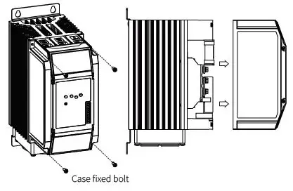
Replacement of Fuse
Case removal
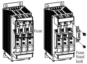
Replacement of fuse
- Fuse none model is not equipped with a rapid fuse inside. Install the suitable fuse for rated load current of the model separately.
- The performance of the product is guaranteed only when using the fuse provided by us. For replacing the fuse, use the recommended fuse.
| Rated load current | Rec. fuse | Manufacturer |
| 25 A | 50FE |
BUSSMANN |
| 35 A | 63ET | |
| 50 A | 80ET | |
| 70 A | 100FE | |
| 100 A | 660GH-160 | HINODE |
| 150 A | 660GH-200 |
Bolt specification
| Rated load current | Case fixed bolt | Fuse fixed bolt |
| 25 / 35 / 50 / 70 A | M3 | M6 |
| 100 A | M4 | Top: M8 Bottom: M6 |
| 150 A | M4 | M8 |
Derating Curve
18, Bansong-ro 513Beon-gil, Haeundae-gu, Busan, Republic of Korea, 48002 www.autonics.com | +82-51-519-3232 | [email protected]


