![]()
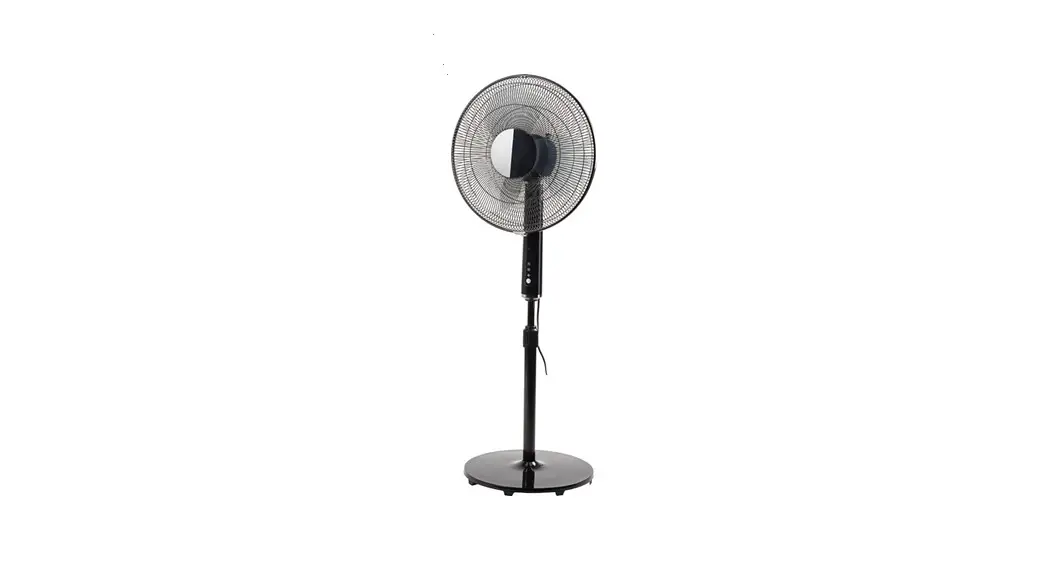
FLOOR FAN
WENTYLATOR STOJACY
![]() Item no. 014758
Item no. 014758
OPERATING INSTRUCTIONS
![]() Important! Read the user instructions carefully before use. Save them for future reference. (Translation of the original instructions)
Important! Read the user instructions carefully before use. Save them for future reference. (Translation of the original instructions)
SAFETY INSTRUCTIONS
- Only intended to be used indoors.
- This product can be used by children from eight years and upwards and by persons with physical, sensorial or mental disabilities, or persons who lack experience or knowledge, if they are supervised or receive instructions concerning the safe use of the product and understand the risks Involved with Its use. Do not allow children to play with the product.
- The product must only be used for its intended purpose and in accordance with these Instructions.
- Do not cover the product, this can result in overheating or fire.
- Place the product standing upright on a level, stable surface.
- When using the product it must always stand upright — it must never be used on its side.
- Pull out the plug from the power point when the product Is not in use. Do not pull the power cord to pull out the plug.
- Leave a free space of a least 30 cm round the product to ensure safe and correct functionality.
- Check that the product can oscillate without colliding with or being obstructed by anything in the near vicinity.
- Never poke any objects into the grille in the product. It Is especially important to explain this to children to make sure they understand the risks.
- Do not use the product If the power cord or plug are damaged, If the product has tipped over, or if It is not working properly.
- Adamaged cord or plug must be replaced by an authorised service centre or qualified person to ensure Safe use.
- Do not use the product outdoors.
- Do not use the product near a bath, shower or swimming pool.
- Do not expose the product to direct sunlight.
- Do not use product together with an external speed controller.
- Do not use the product near flammable liquids or gas.
- Switch off the product and pull out the plug before cleaning.
- Never leave the product unattended when switched on.
- Repairs must only be carried out by an authorised service centre.
- [fthe product stops working properly, switch it off with the switch on the control panel and contact the retailer.
SYMBOLS
| Read the Instructions. | |
| Safety class Il. | |
| Approved in accordance with the relevant directives. | |
| Recycle discarded product in accordance with local regulations. |
TECHNICAL DATA
| Rated voltage | 230 V ~ 50 Hz |
| Input power | 40 W |
| Safety class | ΙΙ |
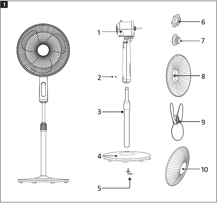
DESCRIPTION
| 1. Motor 2. Lock knob 3. Pillar 4, Foot 5. Angled screw | 6. Plastic nut 7, Fan hub casing 8. Reargrille 9. Fan blade 10. Front grille |
FIG. 1
INSTALLATION
NOTE:
Before installation the angled screws must be removed from the pillar and hub casing, and the plastic nut must be removed from the motor axle.
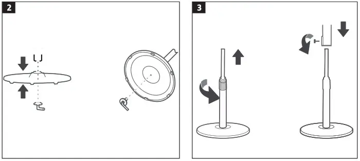
FITTING THE FOOT
Fit the bottom end of the pillar in the foot and screw in place with the angled screw.
FIG. 2
FITTING THE PILLAR
- Pull out the telescopic top part of the pillar to the required height and lock by tightening the height adjusting ring.
- Fit the motor housing and lock in the required position with the lock knob.
FIG. 3
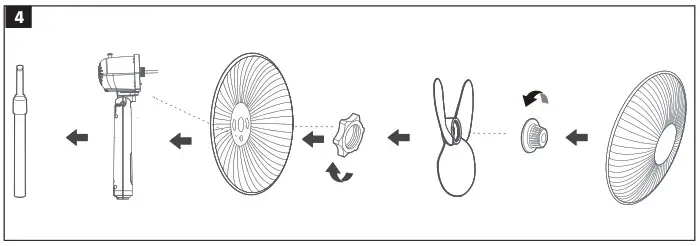
FITTING THE FAN BLADE AND GRILLE
- Align the holes on the back of the grille with the pins on the motor housing.
- Screw on the plastic nut clockwise and tighten to fasten the back grille.
- Push the fan blade on the motor axle and then turn the fan by hand to check that It rotates freely.
- Screw on the fan hub casing anticlockwise and tighten. Now fit the front grille.
FIG. 4
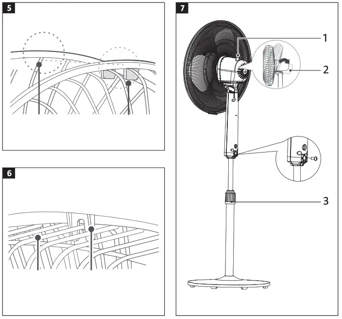
FITTING THE FRONT GRILLE
- Align the clips on the front grille on the top masks on the back grille from above. The correct alignment is shown in the figures, seen from the front from the back of the product.
FIG. 5
FIG. 6
Press the grille halves together with both hands until they lock in place.
HOW TO USE
ADJUSTMENTS
FIG. 7
Oscillation
Connect the oscillation function by pressing the knob (1) on the top of the motor housing. Disconnect the oscillation function by pulling out the knob.
Adjusting the angle
To angle the motor housing (2), and therefore the airflow up or down, carefully press the guard grille up or down.
Height adjustment
To raise or lower the motor housing, release the height adjusting ring (3), pull out or push together the telescopic pillar to the required height and lock by tightening the height adjusting ring.
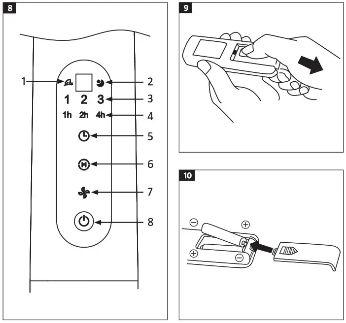
CONTROL PANEL
| 1. Indicator of natural ventilation 2. Indicator night mode 3. Indicator of fan speed 4, Indicator of timing | 5. Timer setting 6. Run mode setting 7 Speed setting 8. Power switch |
FIG. 8
Timer setting
Press the time setting button repeatedly or hold in to stepwise increase the set run time. If for example you want 7 hours of run time, press the button repeatedly until the status lights for 1, 2 and 4 hours go on at the same time. The set runtime is then1+2+4=7 hours. The time status lights go on and off so that the remaining run time is shown in steps of 1 hour. Press the time setting button to run the fan continuously. In continuous run mode all the status lights are off. The timer can also be set from the remote control.
Run mode setting
Press the run mode button M (mode) repeatedly or hold in to step through the run modes normal, natural and night mode. The status lights show the set run mode. The run mode can also be set from the remote control.
Speed setting
Select natural ventilation by pressing the run mode button and then pressing the speed button repeatedly to select the 3 different speeds. The speed can also be set from the remote control.
Power switch
Press the power switch to start and switch off the product. The fan starts working at low speed. Press once again to switch off. The fan can also be started and switched off with the remote control.
USING THE REMOTE CONTROL
Point the remote control at the fan and press the required button. The remote control has a range of 5 metres within an angle of 30 degrees to the left and right of the receiver. eS eS
REPLACING THE BATTERY
- Open the battery compartment by pressing the lid and pulling it out.
FIG. 9 - Insert the batteries with the correct polarity in accordance with the markings inside the battery compartment.
- Replace the cover.
FIG. 10
CLEANING
NOTE:
Pull out the plug from the power point before installation and/or cleaning.
- The fan should be cleaned once a month.
- Clean the fan with a soft cloth moistened with a mild detergent. Make sure that no water or other liquid gets into the fan.
NOTE:
Do not use petrol, solvents or detergents that can damage the plastic parts.
| 14758 | |||
| Description | Designation | Value | Unit |
| Max air speed | F | 46. | m3/min |
| Input power of fan | P | 33.0 | W |
| Operating value | Sy | 1. | (m3/min) W |
| Power consumption in standby mode | PSB | 0,21 | W |
| Sound power level | LwA | 57. | dB(A) |
| Maximum flow speed | C | 219 | m/s |
| Annual power consumption | kWh/a | 10.80 | kWh/a |
| Service value standard: IEC 60879:1986 (corr. 1992) | |||
| Contact details: www.jula.com | |||
Care for the environment!
Must not be discarded with household waste! This product contains electrical or electronic components that should be recycled. Leave the product for recycling at the designated station e.g. the local authority’s recycling station.
Jula reserves the right to make changes. In the event of problems, please contact our customer service. www.jula.com
![]()
For latest version of operating instructions, see www.jula.com
© Jula AB


