
SUNHOPE JHAP-24032A Portable EV Charger
Model: JHAP-24032A/12016A
Important Safety Instructions
- Read this entire document before using the Charger.
- Failure to do so or to follow any of the instructions or warnings in this document can result in fire, electrical shock, serious injury or death.
- Risk of electrical shock or burn.
- The device does not contain any user-serviceable parts.
- Please do not leave until the charging box is in charging status.
- Do not use private power generators as a power source for charging.
- Ensure that the Charger’s charging cable does not obstruct pedestrians or other vehicles or objects.
- Do not operate the Charger in temperatures outside its operating range of 15°C to 50°C.
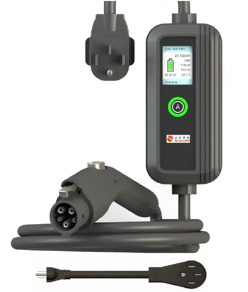
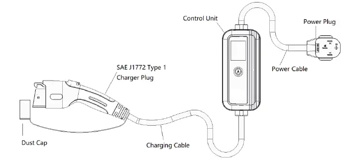
Portable EV Charger Components
The Portable EV Charger Components include:
- Charging Box
- Charging Cable
- Adapter for Outlet 5-20/6-20 (need to purchase)
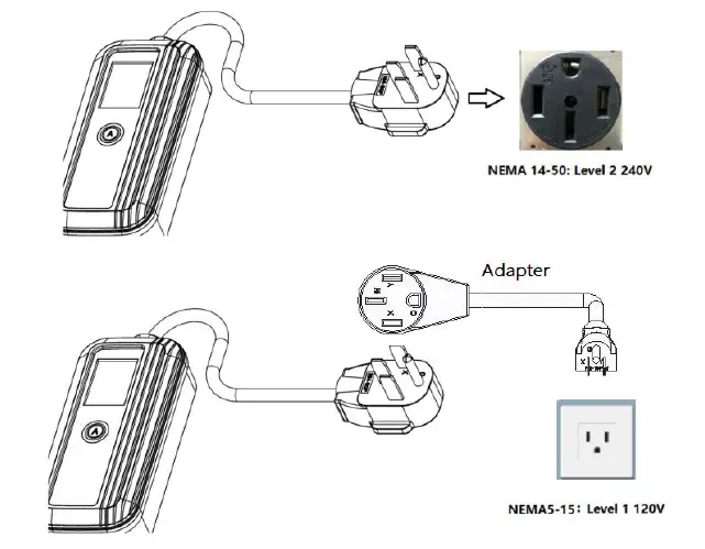
Power Outlet Adapter Specification
The Power Outlet Adapter Specification and Charging Rate Reference for different outlets are as follows:
| Outlet | Rate | Power at 120V | Power at 240V |
|---|---|---|---|
| 5-20* | 16A | 1.4kW | — |
| 5-15 | 12A | 1.9kW | — |
| 6-20* | 16A | — | 3.8kW |
| 14-50 | 32A | — | 7.7kW |
The Adapter for Outlet 5-20/6-20 needs to be purchased separately.
Information of Display Screen and LED Ring Indicator
The Display Screen Information shows the relevant electrical parameters and charging time of the charging operation, and the work/failure bar indicates the working process and fault category.
The LED Ring Indicator Information shows the following states:
| LED Ring Indicator | State |
|---|---|
| Black | The charger is not connected to the power supply |
| Yellow Light 1s Flash | Power system initialization |
| Blue Light On | The vehicle is already connected, waiting to be charged |
| Yellow Light On | Charging is in progress |
| Blue Flashes Green Light On | Charging is completed |
| Yellow Flashes Red | Charging at high-temperature fault |
Operation
Use only on mains power with fault current circuit breaker. Carefully read this guide together with your vehicle owner’s handbook prior to charging your electric vehicle.
Power On
- Firmly insert the power plug into the outlet on the wall.
- When the device is powered on, the system enters a self-test, and the status indicator will display yellow.
- The device is ready when the Status indicator turns blue, and the LCD will display charging information.
- The maximum current is automatically selected according to the socket voltage or at every Power on.
- According to the Power Plug used (14-50P/6-20P/5-15P/5-20P) to select current: Press and hold the current Set button for 5s to select the maximum charging current (By selecting items: 14-50P 32A 240V, 6-20P 16A 240V, 5-20P 16A 120V, 5-15P 12A 120V). Press and hold button for 5s to select item before inserting the charger plug (car side).
Start Charging
Connect the vehicle and the charging connector to begin the charging process.
Important Safety Instructions
Save These Instructions
Read this entire document before using the Charger. Failure to do so or to follow any of the instructions or warnings in this document can result in fire, electrical shock, serious injury or death.
Cautions:
- Risk of electrical shock or burn.
- The device does not contain any user-serviceable parts.
- Please do not leave until the charging box is in charging status.
- Do not use private power generators as a power source for charging.
- Do not operate the Charger in temperatures outside its operating range of -22°F to +122°F (-30°C to +50°C).
Warnings:
- Do not use this product if it is damaged.
- Only use for EV charging. Ventilation not required.
- Connect only to properly grounded outlets.
- Do not use this device with an extension cord or an adapter.
- Automatic CCID reset provided.
- Do not disconnect the Charger from the wall outlet when the vehicle is charging.
- Do not plug the Charger into a damaged, loose or worn power outlet. Ensure that the prongs on the Charger fit snugly into the wall outlet.
- Do not expose the Charger to flammable or harsh chemicals or vapors. Do not use or store the Charger in a recessed area or below floor level. When using the Charger in an inside location such as a garage, position the Charger’s main controller at least 18 inches (46 cm) above the floor.
- Do not use the Charger when either you, the vehicle or the Charger is exposed to severe rain, snow, electrical storm or other inclement weather.
- When transporting the Charger, handle with care to prevent damage to any of its components. Do not subject the Charger to strong force or impact. Do not pull, twist, tangle, drag or step on the Charger or any of its components.
- Protect the Charger from moisture, water and foreign objects at all times. If any exist or appear to have corroded or damaged the Charger, do not use the Charger.
- If rain falls during charging, do not allow rain water to run along the length of charge cable, causing the electrical outlet or charging port to become wet.
- Do not plug the Charger into an electrical outlet that is submerged in water or covered in snow. If, in this situation, the Charger is already plugged in and needs to be unplugged, turn off the breaker before unplugging the Charger.
- Ensure that the Charger’s charging cable does not obstruct pedestrians or other vehicles or objects.
Portable EV Charger Components
Power Outlet Adapter
Specification
- Use only a 120-volt or 240-volt AC supply, 50/60 hertz wall outlet that has a dedicated and properly grounded circuit, and is rated for at least 12A.
- If possible, use a dedicated receptacle with a single socket. If the receptacle has two sockets, do not plug any other items into the other socket.
- The Mobile Connector is 23 feet (7 meters) long. Use an existing outlet or install a new outlet within approximately 13 feet (4 meters) of the vehicle’s charge port and at least 18 inches (45 cm) above the ground.
- Do not use an extension cord, a multi-outlet adapter, a multi-plug, a conversion plug, or a power strip as the power source.
Charging Rate Reference
| Outlet | Rate | Power at 120V |
| 5-20* | 16A | 1.9kW |
| 5-15 | 12A | 1.4kW |
| Outlet | Rate | Power at 240V |
| 6-20* | 16A | 3.8kW |
| 14-50 | 32A | 7.7kW |
The Adapter for Outlet 5-20/6-20 need to purchase
Information of Display Screen and LED Ring Indicator The Display Screen Information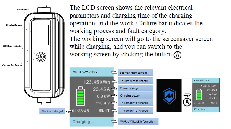
The LED Ring Indicator Information
| LED Ring Indicator | State |
| Black | The charger is not connected to the power supply |
| Yellow Light 1s Flash | Power system initialization |
| Blue Light On | The vehicle is not connected |
| Yellow Light On | Vehicle already connected, waiting to be charged |
| Blue Flashes | Is charging |
| Green Light On | Charging is completed |
| Yellow Flashes | Charging at high-temperature |
| Red | Fault |
Operation
Use only on mains power with fault current circuit breaker.
Carefully read this guide together with your vehicle owner’s handbook prior to charging your electric vehicle.
Power On
- Firmly insert the power plug into the outlet on the wall.
- When the device is powered on, the system enters a self-test, and the status indicator will display yellow. The device is ready when the Status indicator turns blue, and the LCD will display charging information.
- The maximum current is automatically selected according to the socket voltage or at every Power on.
As well, According to the Power Plug used (14-50P/6-20P/5-15P/5-20P) to select current: Press and hold the current Set button for 5s to select the maximum charging current (By selecting items:
- 14-50P 32A 240V
- 6-20P 16A 240V
- 5-20P 16A 120V
- 5-15P 12A 120V
Press and hold button for 5s to select item) before inserting the charger plug (car side).
Start Charging
Connect the vehicle and the charging connector to begin the charging process. The screen displays “charging”, and the LED status indicator is flashing blue.
End Charging
The vehicle ends charging automatically, and the LED status indicator remains green. The user unplugs the vehicle connection, and the LED status indicator remains blue.
With the vehicle unlocked, disconnect the Type 1 charger plug from the vehicle inlet, and disconnect the power plug from the outlet.
Cover the charger plug dust cap and store the charger unit in the bag provided.
Fault
Troubleshooting
| Fault Situation | Method of Operation |
| Status Indicator Light is Not On (white) | 1. Power supply disconnected – Check circuit breaker and ensure breaker is set to ON. |
| 2. Equipment failure. Contact Support | |
|
Charging Cannot Start (yellow or green light) | 1.Charging plug is not correctly inserted into the vehicle – Unplug and Reconnect Securely |
| 2. The vehicle has been set to reserve charging – check the vehicle | |
| 3. The vehicle does not need to charge or vehicle fault- -Check the vehicle | |
|
Charging Time Extended | 1. Vehicle in reserve charging mode |
| 2. Reduced charging due to high temperature. Check current values on LCD Display. | |
| 3. Charging current at max. Check current values on LCD display. | |
|
Steady Red Light | If charging station faults, refer to the fault information displayed on the LCD screen. |
| Disconnect charging plug, shut off the power supply (disconnect the circuit breaker). Wait 30 seconds and turn on power supply to restart system. If the issue persists, contact customer support. |
Possible Causes of Fault
| LCD Display Fault Shown | Status |
| Overcurrent | Overcurrent protection. Charge again after 10-min interval. If overcurrent fault occurs three times, end charging and contact customer support. |
| Overvoltage | Overvoltage protection. Resume charging after the voltage is normalized. |
| Under-voltage | Under-voltage protection. Resume charging after the voltage is normalized. |
| Contactor Err | Contactor status failure. Contact customer support. |
| Over-temperature | Over-temperature protection. Resume charging after temperature is cooled. |
| CCID Leakage | CCID leakage protection. Remove vehicle plug and reconnect after 30 seconds. |
| Ground Fault | Ground-fault protection. Check Outlet for proper grounding and L/N whether or not it is proper. |
| Short Circuit Err | Short circuit protection. Contact customer support. |
| Control Pilot Err | Control pilot failure. Abnormal draw during charging. |
Technical Parameter
| Description | Project | Parameter |
|
Electrical Parameters | Voltage | 120VAC/240VAC, Single-phase, 60Hz |
| Maximum current | 12A/16A/32A (available by button setting socket No.) | |
| Power incoming plug | 14-50P/5-15P | |
| Standby active power consumption | 3W | |
| Internal residual current detection | CCID20 | |
| Electrical protection | Overvoltage, under-voltage, overcurrent, short circuit, grounding fault, overheat protection, surge protection | |
| Interface | display mode | 2.4-inch color dot matrix screen + LED loop |
| charging connector | SAE J1772 type 1 | |
| communication | Bluetooth(backup) | |
| Ambient Condition | working temperature | -22℉~+122℉ over140℉for capacity reduction |
| Storage temperature | -40℉~+176℉ | |
| humidity | ≤95% (No condensation) | |
| altitude | 3km | |
|
Configuration Parameter | levels of protection | Type 4;IK08 |
| charging cable | 23ft | |
| Power cable | 1ft | |
| Dimensions (width * height * depth) | 208*98*57.5mm, excluding the charging cable and power cable | |
| weight | 4.2kg with charging cable and Power cable |
FCC Rules
This device complies with Part 15 of the FCC Rules. Operation is subject to the following two conditions: (1) this device may not cause harmful interference, and (2) this device must accept any interference received, including interference that may cause undesired operation. Changes or modifications not expressly approved by the party responsible for compliance could void the user’s authority to operate the equipment. This equipment has been tested and found to comply with the limits for a Class B digital device, pursuant to part 15 of the FCC Rules. These limits are designed to provide reasonable protection against harmful interference in a residential installation. This equipment generates uses and can radiate radio frequency energy and, if not installed and used in accordance with the instructions, may cause harmful interference to radio communications. However, there is no guarantee that interference will not occur in a particular installation. If this equipment does cause harmful interference to radio or television reception, which can be determined by turning the equipment off and on, the user is encouraged to try to correct the interference by one or more of the following measures:
- Reorient or relocate the receiving antenna.
- Increase the separation between the equipment and receiver.
- Connect the equipment into an outlet on a circuit different from that to which the receiver is connected.
- Consult the dealer or an experienced radio/TV technician for help.
http://www.sunhopepower.com
MODEL: JHAP-24032A/12016A


 Charging User Manual")