![]()
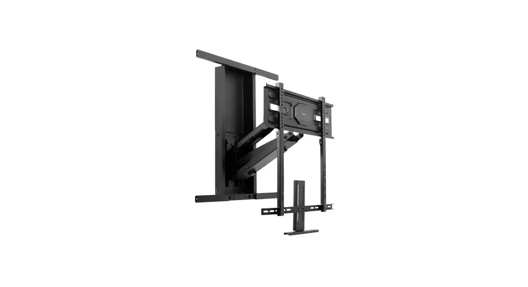
Mechanical Spring Recessed Fireplace TV Mount
Instruction Manual
SKU: MOUNT-M-MM070R
Scan the QR code with your mobile device or follow the link for helpful videos and specifications related to this product. https://vivo-us.com/products/mount-m-mm070r
MOUNT-M-MM070R Mechanical Spring Recessed Fireplace TV Mount
![]() WARNING!
WARNING!
If you do not understand these directions, or if you have any doubts about the safety of the installation, please call a qualified technician. Check carefully to make sure there are no missing or defective parts. Improper installation may cause damage or serious injury. Do not use this product for any purpose that is not explicitly specified in this manual. Do not exceed weight capacity. We cannot be liable for damage or injury caused by improper mounting, incorrect assembly or inappropriate use.
PACKAGE CONTENTS
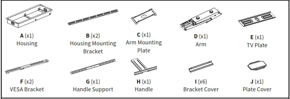
NOTE: NOT ALL HARDWARE INCLUDED WILL BE USED
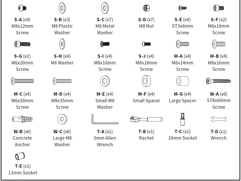
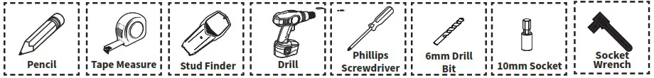
TOOLS NEEDED
![]() WARNING: CHOKING HAZARD
WARNING: CHOKING HAZARD
SMALL PARTS – NOT FOR CHILDREN UNDER 3 YEARS. ADULT SUPERVISION IS REQUIRED.
![]()
DO NOT EXCEED WEIGHT CAPACITY.
Failure to do so may result in serious injury.
![]() CAUTION!
CAUTION!
DO NOT INSTALL INTO DRYWALL ALONE. VERIFY YOUR WALL CONSTRUCTION. USE WOOD STUDS TO MOUNT. We include mounting hardware for brick and concrete walls. If unsure, please contact us at vivo-us.com, email at [email protected], or call us at 309-278-5303.
ASSEMBLY STEPS
STEP 1
To ensure the mount will clear the front of mantel, use the chart below to determine the mounting height. Measure the depth of your mantel, find the closest range in column 1 below, then use column 2 to determine your Mounting Height. Note: Ensure that the edge of the mantel does not exceed 110°F (43°C).
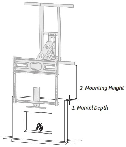
| 1. Mantel Depth | 2. Mounting Height |
| < 30mm/ 1.2” | > 30mm/1.2” |
| < 200mm/ 7.87” | > 140mm/5.51” |
| < 250mm/9.84” | > 170mm/6.69” |
| < 300mm/11.81” | > 200mm/7.87” |
| < 350mm/13.78” | > 250mm/9.84” |
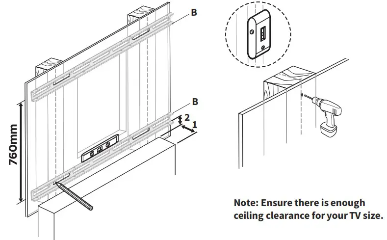
With the Required Mounting Height (2) measurement , use a stud finder and a level to mark the pilot hole locations for the lower Housing Mounting Bracket (B). Mark the upper Housing Mounting Bracket (B) 29.9” (760mm) above the lower holes. Use of a stud finder and level is recommended.
Drill out marked holes 2.4” (60mm) deep using a 1/4” (6mm) drill bit.
Hold Housing (A) in between Housing Mounting Bracket (B) locations. The vertical position should be centered between Housing Mounting Bracket (B) holes previously drilled. With the back side touching the wall, trace the perimeter of Housing (A) using a level and a pencil. Cut and remove the drywall section.
STEP 2
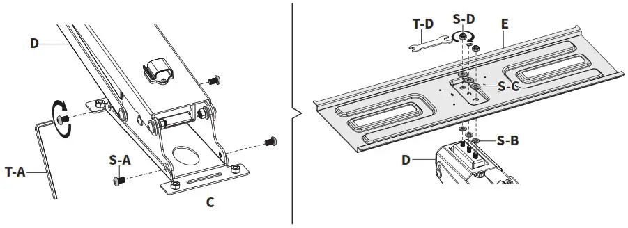
Attach Arm Mounting Plate (C) to Arm (D) using M8x12mm Screws (S-A) and 5mm Allen Wrench (T-A). Connect TV Plate (E) to threaded bolts on Arm (D) using M8 Plastic Washers (S-B), M8 Metal Washers (S-C), M8 Nuts (S-D) and Wrench (T-D).
STEP 3
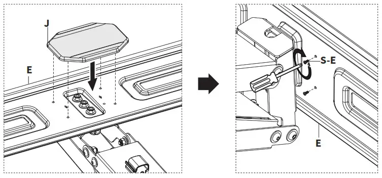
Install Plate Cover (J) to TV Plate (E) using ST3x6mm Screws (S-E) and a Phillips screwdriver.
STEP 4
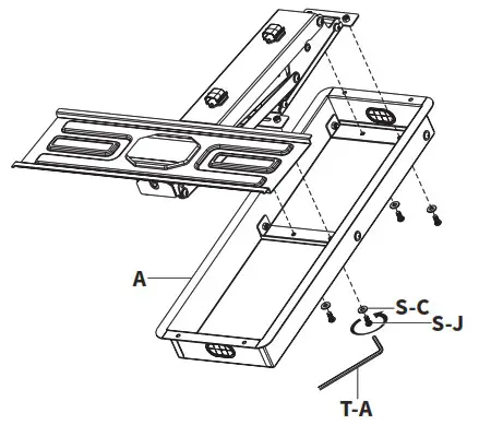
Secure Housing (A) to arm assembly using M8x18mm Screws (S-J), M8 Metal Washers (S-C), and 5mm Allen Wrench (T-A).
STEP 5
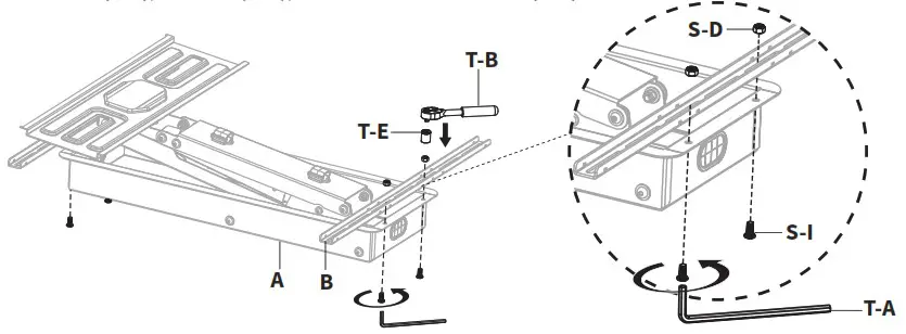
Connect Housing Mounting Brackets (B) to Housing (A) using M8x16mm Screws (S-I), M8 Nuts (S-D), 13mm Socket (T-E), Ratchet (T-B), and 5mm Allen Wrench (T-A).
STEP 6
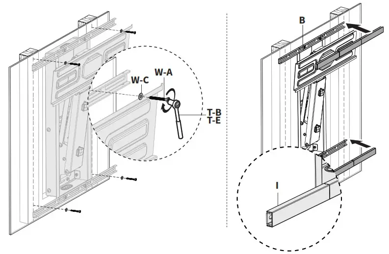
Secure Housing Mounting Brackets (B) with assembly to previously pre-drilled holes using
ST8x60mm Screws (W-A), Large M8 Washers (W-C), 13mm Socket (T-E) with Ratchet (T-B). Place
Bracket Covers (I) over Housing Mounting Brackets (B).
 Please Note: Concrete Anchors (W-B) are provided in custom installation brick/concrete walls.
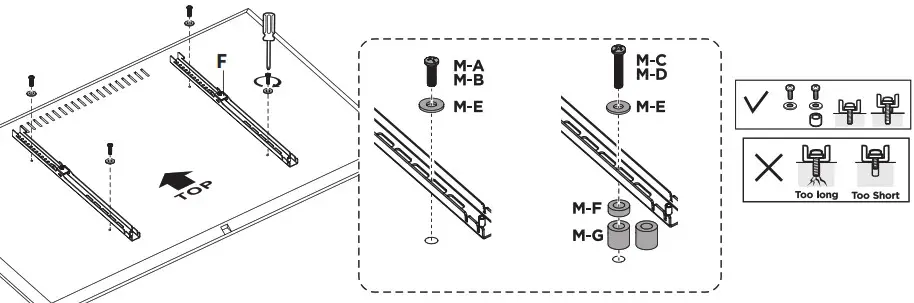
STEP 7
Secure VESA Brackets (F) to back of TV using appropriate Screws (M-A through M-D), Small M8
Washers (M-E), Spacers (M-F, M-G), and a Phillips screwdriver.
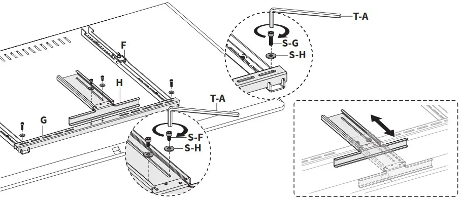
STEP 8
Attach Handle Support (G) to VESA Brackets (F) using M6x20mm Screws (S-G), M6 Washer (S-H), and 5mm Allen Wrench (T-A). Secure Handle (H) to Handle Support (G) using M6x10mm Screws (S-F) and M6 Washers (S-H). Partially secure using 5mm Allen Wrench. Slide Bracket forward and fully tighten screws.
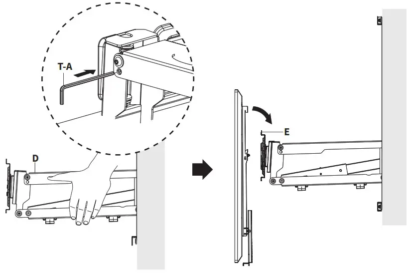
STEP 9
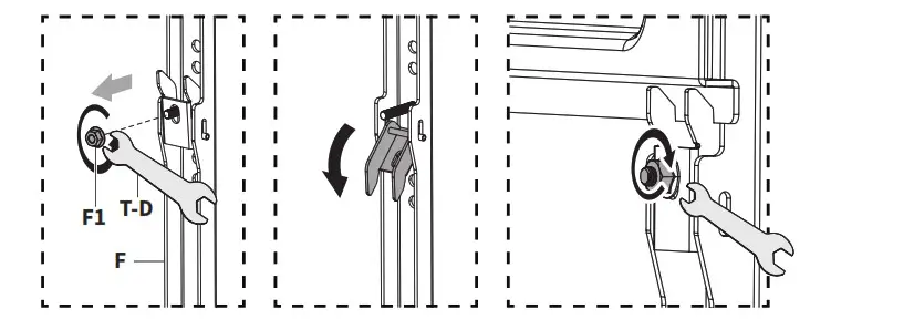
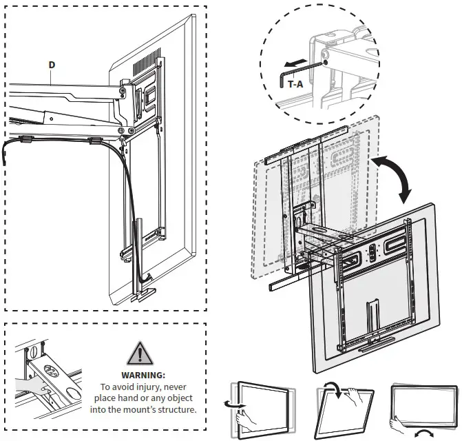
Level mount assembly and insert 5mm Allen Wrench (T-A) into the of the end of Arm (D) to lock it in place. Remove Nuts (F1) from the back of VESA Brackets (F) using Wrench (T-D) and open the latches.
Hang VESA Brackets (F) over TV Plate (E) and secure the latches using Nuts (F1) and Wrench (T-D).
STEP 10
Assemble 10mm Socket (T-C) to Ratchet (T-B). Insert 10mm Socket (T-C) into the adjustment screw on the front of Arm (D). Tighten the adjustment screw using Ratchet (T-B) to set the the indicator to the correct position based on the weight of the TV.
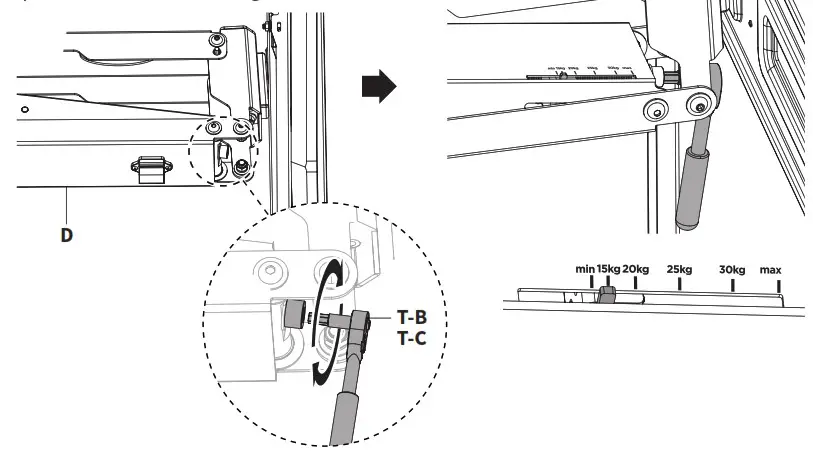
STEP 11
Organize cables using the cable clips located under Arm (D). Remove 5mm Allen Wrench (T-A) from Arm (D) and adjust the TV as desired.
![]() Love your new VIVO setup and want to share?
Love your new VIVO setup and want to share?
Tag us in your photo! @vivo_us
Open Monday – Friday 7:00am – 7:00pm CST,
our dedicated support team can offer immediate assistance with rapid response times. If any parts are received damaged or defective, please contact us. We are happy to replace parts to ensure you have a fully functioning product.
| 309-278-5303 | www.vivo-us.com Chat live with an agent! | [email protected] |
AVG. RESOLUTION TIME (within office hrs): 5M 4S
AVG. RESOLUTION TIME (within office hrs): < 15 M
AVG. RESPONSE TIME (within office hrs): 1HR 8M
– 23% within < 15m
– 38% within < 30m
– 61% within < 1hr
– 83% within < 2hr
– 92% within < 3hr
FOR MORE VIVO PRODUCTS, CHECK OUT OUR WEBSITE AT: www.vivo-us.com
References
 Register a .US.COM domain today!
 VIVO - Desks, Monitor Mounting, and More Home & Office Solutions – VIVO - desk solutions, screen mounting, and more
-
VIVO - Desks, Monitor Mounting, and More Home & Office Solutions – VIVO - desk solutions, screen mounting, and more
-
Mechanical Spring Recessed Fireplace TV Mount – VIVO - desk solutions, screen mounting, and more


