HACH DOC023.98.80076 pHD sc Analog Differential pH ORP Sensor User Manual
Specifications
Specifications are subject to change without notice.
| Specification | Details |
| Operating temperature | –5 to 105 ºC (23 to 221 ºF) |
| Storage temperature | 4 to 70 ºC (40 to 158 ºF) |
| Temperature element | NTC300 thermistor |
| Sensor cable | pHD: 5-conductor (plus 2 shields), 6 m (20 ft); LCP: 5-conductor (plus 1 shield), 3 m (10 ft) |
| Dimensions (length/diameter) | pHD: 271 mm (10.7 in.)/35 mm (1.4 in.); 1-in. NPT; LCP: 187 mm (7.35 in.)/51 mm(2 in.); 1-½ in. NPT |
| Components | Corrosion-resistant materials, fully- submersible |
| Pressure limit | 6.9 bar at 105 ºC (100 psi at 221 ºF) |
| Maximum flow rate | 3 m/s (10 ft/s) |
General information
In no event will the manufacturer be liable for direct, indirect, special, incidental or consequential damages resulting from any defect or omission in this manual. The manufacturer reserves the right to make changes in this manual and the products it describes at any time, without notice or obligation. Revised editions are found on the manufacturer’s website.
Safety information
The manufacturer is not responsible for any damages due tomisapplication or misuse of this product including, without limitation, direct, incidental and consequential damages, and disclaims such damages to the full extent permitted under applicable law. The user is soley responsible to identify critical application risks and install appropriate mechanisms to protect processes during a possible equipment malfunction.
Please read this entire manual before unpacking, setting up or operating this equipment. Pay attention to all danger and caution statements. Failure to do so could result in serious injury to the operator or damage to the equipment.
Make sure that the protection provided by this equipment is not impaired. Do not use or install this equipment in any manner other than that specified in this manual.
Use of hazard information
![]() DANGER
DANGER
Indicates a potentially or imminently hazardous situation which, if not avoided, will result in death or serious injury.
![]() WARNING
WARNING
Indicates a potentially or imminently hazardous situation which, if not avoided, could result in death or serious injury.
![]() CAUTION
CAUTION
Indicates a potentially hazardous situation that may result in minor or moderate injury.
NOTICE
Indicates a situation which, if not avoided, may cause damage to the instrument. Information that requires special emphasis.
Precautionary labels
Read all labels and tags attached to the instrument. Personal injury or damage to the instrument could occur if not observed. A symbol on the instrument is referenced in the manual with a precautionary statement.
| This is the safety alert symbol. Obey all safety messages that follow this symbol to avoid potential injury. If on the instrument, refer to the instruction manual for operation or safety information. |
| This symbol indicates that a risk of electrical shock and/or electrocution exists. | |
| This symbol indicates the presence of devices sensitive to Electro-static Discharge (ESD) and indicates that care must be taken to prevent damage with the equipment. | |
| Electrical equipment marked with this symbol may not be disposed of in European domestic or public disposal systems. Return old or end-of-life equipment to the manufacturer for disposal at no charge to the user. |
Product overview
This sensor is designed to work with a controller for data collection and operation. Multiple controllers can be used with this sensor. This document assumes sensor installation and use with an sc200 controller. To use the sensor with other controllers, refer to the user manual for the controller that is used.
The sensor is available in different styles. Refer to Figure 1.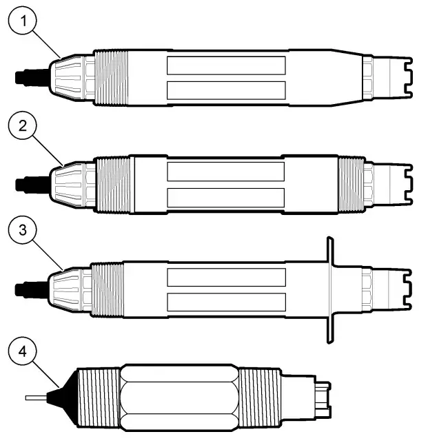
Sensor styles
| 1 Insertion—allows removal without stopping the process flow | 3 Sanitary—for install in a 2-inch sanitary tee |
| 2 Convertible—for a pipe tee or immersion in an open vessel | 4 Convertible—LCP type |
Installation
Mounting
![]() WARNING
WARNING
Personal injury hazard. Removal of a sensor from a pressurized vessel can be dangerous. Installation and removal of these sensors should be done by individuals trained in proper high pressure and temperature installation. Always use industry approved hardware and safety procedures when dealing with high pressure and/or temperature fluid transport systems.
Figure 2 Mounting examples (1)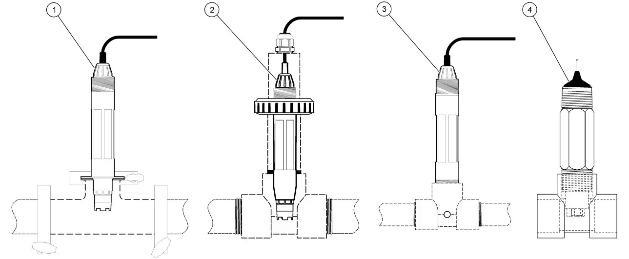
| 1 Sanitary mount | 3 Flow-through mount |
| 2 Union mount | 4 Flow-through mount—LCP sensor |
For examples of sensors in different applications, refer to Figure 2 and Figure 3. The sensor must be calibrated before use. Refer to Calibrate the sensor on page 12.
Figure 3 Mounting examples (2)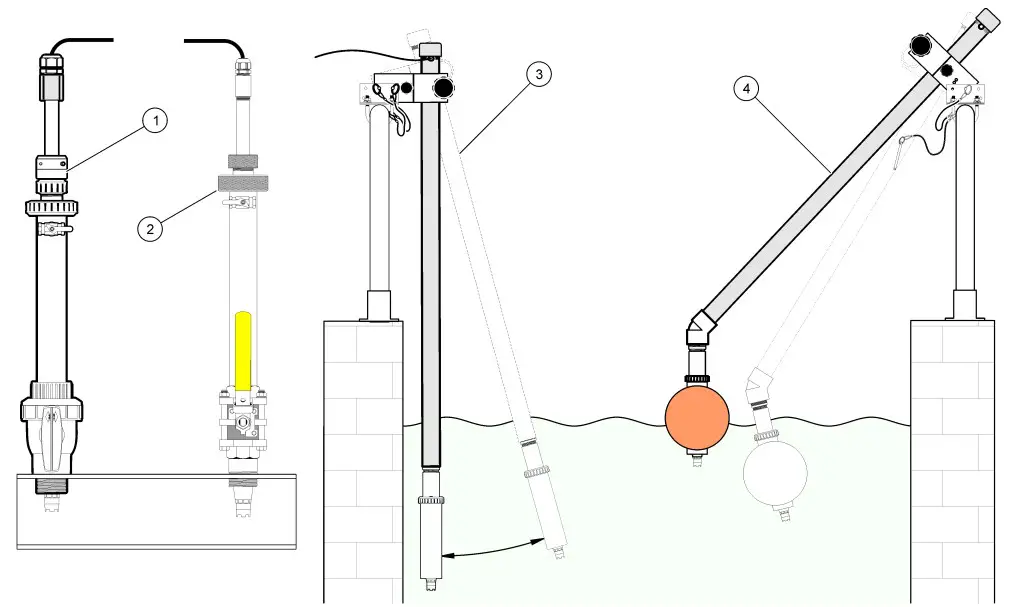
| 1 PVS insertion mount | 3 Immersion mount |
| 2 Insertion mount | 4 Immersion mount, ball float |
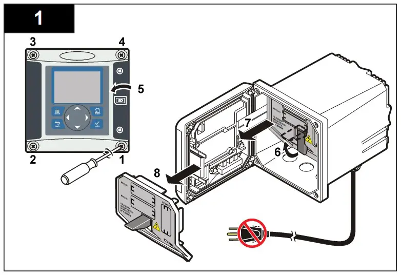
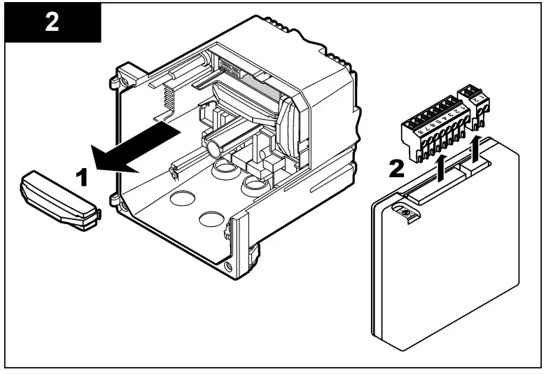
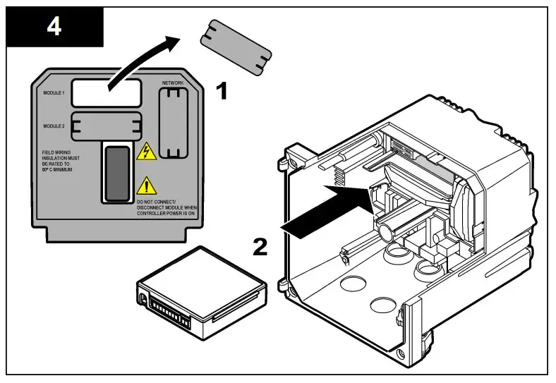
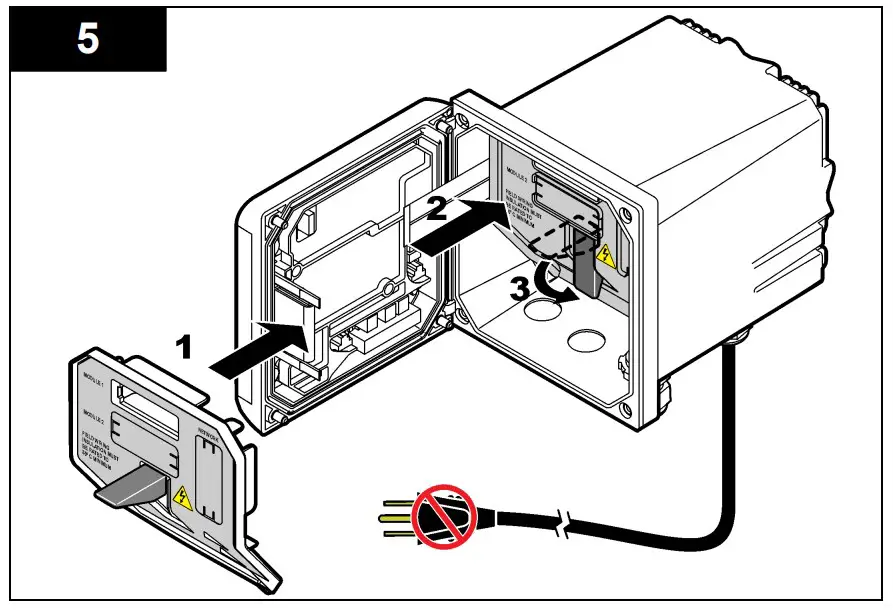
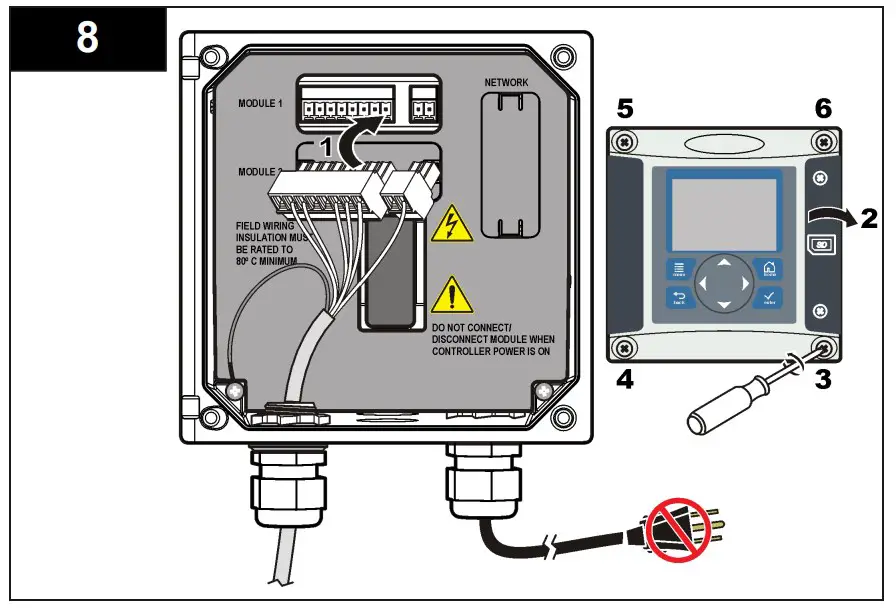
Connect the sensor to the module
![]() Warning
Warning![]() Potential Electrocution Hazard. Always disconnect power to the instrument when making electrical connections.
Potential Electrocution Hazard. Always disconnect power to the instrument when making electrical connections.
![]() Warning
Warning
Electrocution Hazard. High voltage wiring for the controller is conducted behind the high voltage barrier in the controller enclosure. The barrier must remain in place except when installing modules, or when a qualified installation technician is wiring for power, relays or analog and network cards.
NOTICE
![]() Potential Instrument Damage. Delicate internal electronic components can be damaged by static electricity, resulting in degraded performance or eventual failure.
Potential Instrument Damage. Delicate internal electronic components can be damaged by static electricity, resulting in degraded performance or eventual failure.
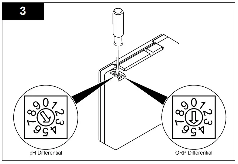
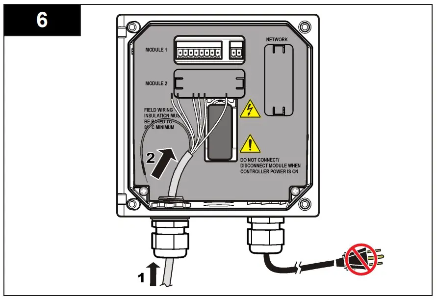
To install the module and connect the sensor, refer to the illustrated steps on page 9 and Table 2.
Note: If the sensor cable is not long enough to reach the controller, an interconnect cable and junction box are required to extend the distance.
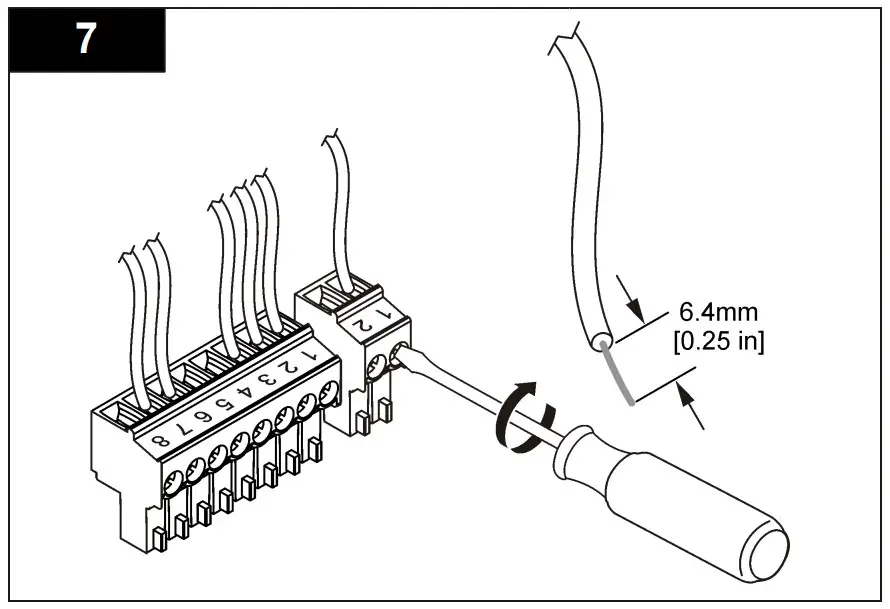
Table 2 pH and ORP differential sensor wiring
| Connector | Pin no. | Signal | Sensor wire |
| 8-pin | 1 | Reference | Green |
| 2 | Inner shield | Clear | |
| 3 | –V supply | White | |
| 4 | — | — | |
| 5 | — | — | |
| 6 | Temp + | Yellow | |
| 7 | Temp – /Circuit low | Black | |
| 8 | — | — | |
| 2-pin | 1 | Active | Red |
| 2 | — | — | |
| Sensor shield wires – Connect all sensor ground/shield wires to the controller enclosure grounding screws. | Clear with black band | ||
Installation Instruction
Operation
Guidelines for operation
![]() CAUTION
CAUTION
Personal injury hazard. The glass bulb or shank on the sensor can break. Handle the sensor carefully to prevent injury.
- Remove the protective cap before the sensor is put into the process.
- When the sensor is removed from the process for >1 hour, fill the protective cap with pH 4 buffer (recommended) or tap water and put the cap on the sensor. Repeat every 2–4 weeks for extended storage.
User navigation
Refer to the controller documentation for keypad description and navigation information.
Push the RIGHT arrow key on the controller multiple times to show more information on the home screen and to show a graphical display.
Configure the sensor
Use the Configure menu to enter identification information for the sensor and to change options for data handling and storage. The following procedure can be used to configure pH or ORP sensors.
- Push the MENU key and select Sensor Setup, [Select Sensor], Configure.
- Use the arrow keys to select an option and push ENTER. To enter numbers, characters or punctuation, push and hold the UP or DOWN arrow keys. Push the RIGHT arrow key to advance to the next space.
| Option | Description |
| EDIT NAME | Changes the name that corresponds to the sensor on the top of the measure screen. The name is limited to 10 characters in any combination of letters, numbers, spaces or punctuation. |
| SENSOR S/N | Allows the user to enter the serial number of the sensor, limited to 16 characters in any combination of letters, numbers, spaces or punctuation. |
| DISPLAY FORMAT | For pH sensors only—changes the number of decimal places that are shown on the measure screen to XX.XX (default) or XX.X |
| TEMP UNITS | Sets the temperature units to °C (default) or °F |
| TEMP ELEMENT | pH sensors—sets the temperature element for automatic temperature compensation to PT100, PT1000 or NTC300 (default). If no element is used, the type can be set to manual and a value for temperature compensation can be entered (manual default: 25 °C). ORP sensors— temperature compensation is not used. A temperature element can be connected to measure temperature. |
| FILTER | Sets a time constant to increase signal stability. The time constant calculates the average value during a specified time—0 (no effect, default) to 60 seconds (average of signal value for 60 seconds). The filter increases the time for the sensor signal to respond to actual changes in the process. |
| PURE H2O COMP | For pH sensors only—adds a temperaturedependent correction to the measured pH value for pure water with additives—None (default), Ammonia, Morpholine or User defined. For process temperatures above 50 °C, the correction at 50 °C is used. For user-defined applications, a linear slope (default: 0 pH/°C) can be entered. |
| SET ISO POINT | At the isopotential point, the pH slope is independent of temperature. Most sensors have an isopotential point of 7.00 pH (default), however sensors for special applications may have a different isopotential value. |
| LOG SETUP | Sets the time interval for data storage in the data log—5, 30 seconds, 1, 2, 5, 10, 15 (default), 30, 60 minutes |
| RESET DEFAULTS | Sets the configuration menu to the default settings. All sensor information is lost. |
Calibrate the sensor
About sensor calibration
Calibration adjusts the sensor reading to match the value of one or more reference solutions. The sensor characteristics slowly shift over time and cause the sensor to lose accuracy. The sensor must be calibrated regularly to maintain accuracy. The calibration frequency varies with the application and is best determined by experience.
A temperature element is used to provide pH readings that are automatically adjusted to 25 °C for temperature changes that affect the active and reference electrode. This adjustment can be manually set by the customer if the process temperature is constant.
During calibration, data is not sent to the datalog. Thus, the datalog can have areas where the data is intermittent.
pH calibration procedure
Sensors can be calibrated with 1 or 2 reference solutions (1-point or 2- point calibration). Standard buffers are automatically recognized. Make sure that the correct buffer set is used (refer to Change calibration options on page 15).
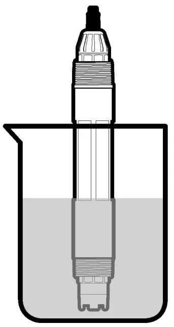
- Put the sensor in the first reference solution. Make sure that the sensor portion of the probe is fully immersed in the liquid (Figure 4).
Figure 4 Sensor in reference solution
- Wait for the sensor and solution temperature to equalize. This can take 30 minutes or more if the temperature difference between the process and reference solution is significant.
- Push the MENU key and select Sensor Setup, [Select Sensor], Calibrate.
Option Description 2 point buffer Use 2 buffers for calibration, for example pH 7 and pH 4 (recommended method). The buffers must be from the buffer set that is specified in the Cal Options menu (refer to Change calibration options on page 15). 1 point buffer Use 1 buffer for calibration, for example pH 7. The buffer must be from the buffer set that is specified in the Cal Options menu. 2 point sample Use 2 samples or buffers of known pH value for calibration. Determine the pH value of samples with a different instrument. 1 point sample Use 1 sample or buffer for calibration. Determine the pH value of samples with a different instrument - Select the type of calibration:
- Put the sensor in the first reference solution. Make sure that the sensor portion of the probe is fully immersed in the liquid (Figure 4).
If the passcode is enabled in the security menu for the controller, enter the passcode.Select the option for the output signal during calibration:
| Option | Description |
| Active | The instrument sends the current measured output value during the calibration procedure. |
| Hold | The sensor output value is held at the current measured value during the calibration procedure. |
| Transfer | A preset output value is sent during calibration. Refer to the controller user manual to change the preset value |
- With the sensor in the first reference solution, push ENTER. The measured value is shown.
Wait for the value to stabilize and push ENTER.
Note:
- The screen may advance to the next step automatically.
- If the reference solution is a sample, measure the pH value with a secondary verification instrument. Use the arrow keys to enter the measured value and push ENTER.
Note:
- If a pH buffer not listed the Cal Options menu is used, refer to the buffer bottle to find the pH value that corresponds to the temperature of the buffer.
- For a 2-point calibration, measure the second reference solution (or sample):
- Remove the sensor from the first solution and rinse with clean water.
- Put the sensor in the next reference solution and push
ENTER
- .
- Wait for the value to stabilize. Push
ENTER.
Note:
- The screen may advance to the next step automatically.
- If the reference solution is a sample, measure the pH value with a secondary verification instrument. Use the arrow keys to enter the measured value and push
ENTER.
- Review the calibration result:
- Passed—the sensor is calibrated and ready to measure samples. The slope and/or offset values are shown.
- Failed—the calibration slope or offset is outside of accepted limits. Repeat the calibration with fresh reference solutions. Refer to mAINTENANCE n page 16 and Troubleshooting on page 17 for more information.
- If the calibration passed, push ENTER to continue.
- If the option for operator ID is set to Yes in the Calibration Options menu, enter an operator ID. Refer to Change calibration options on page 15.
- On the New Sensor screen, select whether the sensor is new:
Option Description Yes The sensor was not calibrated previously with this controller. The days of operation and previous calibration curves for the sensor are reset. No The sensor was calibrated previously with this - Return the sensor to the process and push ENTER.
The output signal returns to the active state and the measured sample value is shown on the measure screen.
Note: If the output mode is set to hold or transfer, select the delay time when
the outputs return to the active state.
ORP calibration procedure
Sensors can be calibrated with an ORP reference solution or with the process sample.
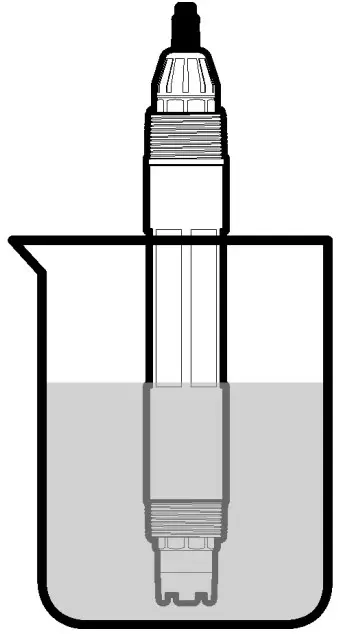
- Put the sensor in the reference solution. Make sure that the sensor portion of the probe is fully immersed in the solution (Figure 5).
Figure 5 Sensor in reference solution
- Push the MENU key and select Sensor Setup, [Select Sensor], Calibrate.
- Push ENTER to select 1 Point Sample calibration.
- If the passcode is enabled in the security menu for the controller, enter the passcode.
Option Description Active The instrument sends the current measured output value during the calibration procedure. Hold The sensor output value is held at the current measured value during the calibration procedure. Transfer A preset output value is sent during calibration. Refer to the controller user manual to change the preset value - Select the option for the output signal during calibration:
- With the sensor in the reference solution or sample, push ENTER. The measured value is shown.
- Wait for the value to stabilize and push ENTER.
Note: The screen may advance to the next step automatically. - If the process sample is used for calibration, measure the ORP value with a secondary verification instrument. Use the arrow keys to enter the value and push ENTER.
- Review the calibration result:
- Passed the sensor is calibrated and ready to measure samples. The slope and/or offset values are shown.
- Failed the calibration slope or offset is outside of accepted limits. Repeat the calibration with fresh reference solutions. Refer to Maintenance on page 16 and Troubleshooting on page 17 for more information.
- If the calibration passed, push ENTER to continue.
- If the option for operator ID is set to Yes in the Calibration Options menu, enter an operator ID. Refer to Change calibration options on page 15.
- On the New Sensor screen, select whether the sensor is new:
Option Description Yes The sensor was not calibrated previously with this controller. The days of operation and previous calibration curves for the sensor are reset. No The sensor was calibrated previously with this - Return the sensor to the process and push ENTER. The output signal returns to the active state and the measured sample value is shown on the measure screen.
Note: If the output mode is set to hold or transfer, select the delay time when the outputs return to the active state.
Temperature calibration
The instrument is calibrated at the factory for accurate temperature measurement. The temperature can be calibrated to increase accuracy.
- Put the sensor in a container of water that is at a known temperature. Measure the temperature of the water with an accurate thermometer or independent instrument.
- Push the MENU key and select Sensor Setup, [Select Sensor], Calibrate.
- Select 1 PT Temp Cal and push ENTER.
- Wait for the value to stabilize and push ENTER.
- Enter the exact value and push ENTER.
- Return the sensor to the process and push ENTER.
Exit calibration procedure
If the BACK key is pushed during a calibration, the user can exit the calibration.
- Push the BACK key during a calibration. Three options are shown:
Option Description QUIT CAL Stop the calibration. A new calibration must start from the beginning. BACK TO CAL Return to the calibration. LEAVE CAL Exit the calibration temporarily. Access to other menus is allowed. A calibration for a second sensor (if present) can be started. To return to the calibration, push the MENU key and select Sensor Setup, [Select Sensor - Use the arrow keys to select one of the options and push ENTER.
Change calibration options
The user can set a reminder or include an operator ID with calibration data from the CAL OPTIONS menu.
- Push the MENU key and select Sensor Setup, [Select Sensor], Calibrate, Cal Options.
- Use the arrow keys to select an option and push ENTER.
| Option | Description |
| SELECT BUFFER | For pH sensors only—changes the set of buffer solutions that are recognized for calibration to pH 4.00, 7.00, 10.00 (default set) or DIN 19267 (pH 1.09, 4.65, 6.79, 9.23, 12.75) Note: Other buffers can be used if the 1 point sample or 2 point sample option is selected during calibration. |
| CAL REMINDER | Sets a reminder for the next calibration in days, months or years—Off (default), 1 day, 7, 30, 60, or 90 days, 6 or 9 months, 1 or 2 years |
| OP ID on CAL | Includes an operator ID with calibration data— Yes or No (default). The ID is entered during the calibration. |
Reset calibration options
The calibration options can be reset to the factory default options.
- Push the MENU key and select Sensor Setup, [Select Sensor], Calibrate, Reset Default Cal.
- If the passcode is enabled in the security menu for the controller, enter the passcode.
- Push ENTER. The Reset Cal? screen is shown.
- Push ENTER. All calibration options are set to the default values.
- If the option for operator ID is set to Yes in the Calibration Options menu, enter an operator ID. Refer to Change calibration options on page 15.
- On the New Sensor screen, select whether the sensor is new:
Option Description Yes The sensor was not calibrated previously with this controller. The days of operation and previous calibration curves for the sensor are reset. No The sensor was calibrated previously with this controller - Push the BACK key to return to the measure screen.
Impedance measurements
To increase the reliability of the pH measurement system, the controller determines the impedance of the glass electrodes. This measurement is taken every minute. During diagnostics, the pH measurement reading will be on hold for five seconds. If an error message appears, refer to Error list on page 19 for more details.
To enable/disable the sensor impedance measurement:
- Push the MENU key and select Sensor Setup.
- Select Diag/test and push ENTER.
- Select Imped Status and push ENTER.
- Select Enable/Disable and push ENTER
To see both actual and reference sensor impedance readings:
- Push the MENU key and select Sensor Setup.
- Select Diag/test and push ENTER.
- Select sensor signals and push ENTER
Modbus registers
A list of Modbus registers is available for network communication. Refer to the manufacturer’s website for more information.
Maintenance
![]() WARNING
WARNING
Personal injury hazard. Only qualified personnel should conduct the tasks described in this section of the manual.
Maintenance schedule
The maintenance schedule shows minimum times for regular maintenance tasks. Perform maintenance tasks more frequently for applications that cause electrode fouling.
| Maintenance task | 90 days | Annually |
| Clean the sensor | X | |
| Inspect sensor for damage | X | |
| Replace salt bridge and fill solution | X | |
| Calibrate sensor | Set by regulatory agencies or experience | |
Clean the sensor
| WARNING | |
| Chemical exposure hazard. Obey laboratory safety procedures and wear all of the personal protective equipment appropriate to the chemicals that are handled. Refer to the current safety data sheets (MSDS/SDS) for safety protocols. | |
![]() WARNING
WARNING
Personal injury hazard. Removal of a sensor from a pressurized vessel can be dangerous. Installation and removal of these sensors should be done by individuals trained in proper high pressure and temperature installation. Always use industry approved hardware and safety procedures when dealing with high pressure and/or temperature fluid transport systems.
Pre-requisite: Prepare a mild soap solution with a non-abrasive dishwashing detergent that does not contain lanolin. Lanolin leaves a film on the electrode surface that can degrade the sensor performance. Examine the sensor periodically for debris and deposits. Clean the sensor when there is a buildup of deposits or when performance has degraded.
- Use a clean, soft cloth to remove loose debris from the end of the sensor. Rinse the sensor with clean, warm water.
- Soak the sensor for 2 to 3 minutes in the soap solution.
- Use a soft bristle brush to scrub the entire measuring end of the sensor.
- If debris remains, soak the measuring end of the sensor in a dilute acid solution such as < 5% HCl for a maximum of 5 minutes.
- Rinse the sensor with water and then return to the soap solution for 2 to 3 minutes.
- Rinse the sensor with clean water.
Note: Sensors with antimony electrodes for HF applications may require
additional cleaning. Contact technical support.
Always calibrate the sensor after maintenance procedures are done.
Replace the salt bridge
Differential sensors have a removable salt bridge (Figure 6). If the sensor has been cleaned but fails calibration, replace the salt bridge and the standard cell solution. Refer to the instructions included with the salt bridge.
Figure 6 Salt bridge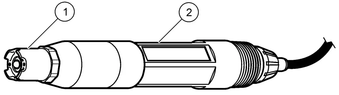
| 1 Salt bridge | 2 Differential sensor |
Always calibrate the sensor after maintenance procedures.
Troubleshooting
Intermittent data
During calibration, data is not sent to the datalog. Thus, the datalog can have areas where the data is intermittent.
Test the pH sensor
Pre-requisites: Two pH buffers and a multimeter. If a calibration fails, first complete the maintenance procedures in Maintenance on page 16.
- Put the sensor in a pH 7 buffer solution and wait for the temperature of the sensor and buffer to reach room temperature.
- Disconnect the red, green, yellow and black sensor wires from the module.
- Measure the resistance between the yellow and black wires to verify the operation of the temperature element. The resistance should be between 250 and 350 ohms at approximately 25 ºC. If the temperature element is good, reconnect the yellow and black wires to the module.
- Measure the DC mV with the multimeter (+) lead connected to the red wire and the (–) lead connected to the green wire. The reading should be between –50 and + 50 mV. If the reading is outside of these limits, clean the sensor and change
the salt bridge and standard cell solution. - With the multimeter still connected the same way, rinse the sensor with water and put it in a pH 4 or pH 10 buffer solution. Wait for the temperature of the sensor and buffer to reach room temperature.
- Compare the mV reading in the pH 4 or 10 buffer to the reading in the pH 7 buffer. The reading should differ by approximately 160 mV. If the difference is less than 160 mV, call technical support.
Test the ORP sensor
Pre-requisites: 200 mV ORP reference solution, multimeter. If a calibration fails, first complete the maintenance procedures in Maintenance on page 16.
- Put the sensor in a 200 mV reference solution and wait for the temperature of the sensor and solution to reach room temperature.
- Disconnect the red, green, yellow and black sensor wires from the module.
- Measure the resistance between the yellow and black wires to verify the operation of the temperature element. The resistance should be between 250 and 350 ohms at approximately 25 ºC.
If the temperature element is good, reconnect the yellow and black wires to the module. - Measure the DC mV with the multimeter (+) lead connected to the red wire and the (–) lead connected to the green wire. The reading should be between 160 and 240 mV.
If the reading is outside of these limits, call technical support.
The sensor diagnostic and test menu shows current and historical information about the instrument. Refer to Table 3. To access the sensor diagnostic and test menu, push the MENU key and select Sensor Setup, [Select Sensor], DIAG/TEST.
Table 3 Sensor DIAG/TEST menu
| Option | Description |
| MODULE INFORMATION | Shows the version and the serial number for the sensor module. |
| SENSOR INFORMATION | Shows the name and serial number that was entered by the user. |
| CAL DAYS | Shows the number of days since the last calibration. |
| CAL HISTORY | Shows a list of and details for each calibration. |
| RESET CAL HISTORY | Resets the calibration history for the sensor (requires service-level passcode). All previous calibration data is lost. |
| SENSOR SIGNALS | Shows the current reading in mV, the impedance of the active and reference electrodes and the temperature-compensated impedance. Shows predicted life when Predict Enable is on. |
| IMPED STATUS | Shows when the impedance of the sensor (measured every 3 hours) indicates malfunction. If enabled (recommended), a warning is shown when the impedance is outside of normal limits. |
| PREDICT ENABLE | Adds the predicted life of the pH sensor to the Sensor Signals screen. The Impedance Status must be enabled and the sensor must have a 2-point calibration for accurate prediction.When the predicted life has expired, a warning is shown on the measurement screen. |
Table 3 Sensor DIAG/TEST menu (continued)
| Option | Description |
| SENSOR DAYS | Shows the number of days that the sensor has been in operation. |
| RESET SENSOR DAYS | Resets the number of days that the sensor has been in operation. |
Error list
When an error occurs, the reading on the measurement screen flashes and all outputs are held when specified in the controller menu. To show the sensor errors, press the MENU key and select Sensor Diag, [Select Sensor], Error List. A list of possible errors is shown in Table 4.
Table 4 Error list for pH and ORP sensors
| Error | Description | Resolution |
| PH TOO HIGH | The measured pH is > 14 | Calibrate or replace the sensor. |
| ORP TOO HIGH | The measured ORP value is > 2100 mV | |
| PH TOO LOW | The measured pH is < 0 | Calibrate or replace the sensor. |
| ORP TOO LOW | The measured ORP value is < –2100 mV | |
| OFFSET TOO HIGH | The offset is > 9 (pH) or 200 mV (ORP) | Follow the maintenance procedures for the sensor and then repeat the calibration, or replace the sensor. |
| OFFSET TOO LOW | The offset is < 5 (pH) or –200 mV (ORP) | |
| SLOPE TOO HIGH | The slope is >62 (pH)/1.3 (ORP) | Repeat the calibration with a fresh buffer or sample, or replace the sensor. |
Table 4 Error list for pH and ORP sensors (continued)
| Error | Description | Resolution |
| SLOPE TOO LOW | The slope is <50 (pH)/0.7 (ORP) | Clean the sensor, then repeat the calibration, or replace the sensor. |
| TEMP TOO HIGH | The measured temperature is >130 °C | Make sure that the correct temperature element is selected. |
| TEMP TOO LOW | The measured temperature is < –10 °C | |
| ADC FAILURE | The analog to digital conversion failed | Power off and power on the controller. Call technical support. |
| A ELEC TOO HIGH | The active electrode impedance is > 900 MΩ | The sensor is in air. Return the sensor to the process. |
| A ELEC TOO LOW | The active electrode impedance is < 8 MΩ | The sensor is damaged or dirty. Call technical support. |
| R ELEC TOO HIGH | The reference electrode impedance is > 900 MΩ | Buffer leaked or evaporated. Call technical support. |
| R ELEC TOO LOW | The reference electrode impedance is < 8 MΩ | The reference electrode is damaged. Call technical support. |
| SAME BUFFER | The buffers for 2 point buffer calibration have the same value | Complete the steps in Test the pH sensor on page 17. |
| SENSOR MISSING | The sensor is missing or disconnected | Examine the wiring and connections for the sensor and for the module. |
Table 4 Error list for pH and ORP sensors (continued)
| Error | Description | Resolution |
| TEMP MISSING | The temperature sensor is missing | Examine the wiring for the temperature sensor. Make sure that the correct temperature element is selected. |
| GLASS IMP LOW | The glass bulb is broken or reached end of life | Replace the sensor. Call technical support. |
Warning list for sensors
A warning does not affect the operation of menus, relays and outputs. A warning icon flashes and a message is shown on the bottom of the measurement screen. To show the sensor warnings, press the MENU key and select Sensor Diag, [Select Sensor], Warning List. A list of possible warnings is shown in Table 5.
Table 5 Warning list for pH and ORP analog sensors
| Warning | Description | Resolution |
| PH TOO HIGH | The measured pH is > 13 | Calibrate or replace the sensor. |
| ORP TOO HIGH | The measured ORP value is > 2100 mV | |
| PH TOO LOW | The measured pH is < 1 | Calibrate or replace the sensor. |
| ORP TOO LOW | The measured ORP value is < –2100 mV | |
| OFFSET TOO HIGH | The offset is > 8 (pH) or 200 mV (ORP) | Follow the maintenance procedures for the sensor and then repeat the calibration. |
| OFFSET TOO LOW | The offset is < 6 (pH) or –200 mV (ORP) |
Table 5 Warning list for pH and ORP analog sensors (continued)
| Warning | Description | Resolution |
| SLOPE TOO HIGH | The slope is >60 (pH)/1.3 (ORP) | Repeat the calibration with a fresh buffer or sample. |
| SLOPE TOO LOW | The slope is <54 (pH)/0.7 (ORP) | Clean the sensor, then repeat the calibration. |
| TEMP TOO HIGH | The measured temperature is >100 °C | Make sure the right temperature element is used. |
| TEMP TOO LOW | The measured temperature is < 0 °C | |
| CAL OVERDUE | The Cal Reminder time has expired | Calibrate the sensor. |
| REPLACE SENSOR | The sensor has been in operation > 365 days, or the predicted life has expired (Refer to Sensor diagnostic and test menu on page 18) | Replace the sensor. |
| NOT CALIBRATED | The sensor has not been calibrated | Calibrate the sensor. |
| FLASH FAILURE | External flash memory failed | Contact technical support. |
| A ELEC TOO HIGH | The active electrode impedance is > 800 MΩ | The sensor is in air. Return the sensor to the process. |
| A ELEC TOO LOW | The active electrode impedance is < 15 MΩ | The sensor is damaged or dirty. Call technical support. |
Table 5 Warning list for pH and ORP analog sensors (continued)
| Warning | Description | Resolution |
| R ELEC TOO HIGH | The reference electrode impedance is > 800 MΩ | Buffer leaked or evaporated. Call technical support. |
| R ELEC TOO LOW | The reference electrode impedance is < 15 MΩ | The reference electrode is damaged. Call technical support. |
| CAL IN PROGRESS | A calibration was started but not completed | Return to calibration. |
Event list for sensors
The event list shows current activities such as configuration changes, alarms, warning conditions, etc. To show the events, press the MENU key and select Sensor Diag, [Select Sensor], Event List. A list of possible events is shown in Table 6. Previous events are recorded in the event log, which can be downloaded from the controller. Refer to the controller documentation for data retrieval options.
Table 6 Event list for pH and ORP sensors
| Event | Description |
| CAL READY | The sensor is ready for calibration |
| CAL OK | The current calibration is good |
| TIME EXPIRED | The stabilization time during calibration expired |
| NO BUFFER | No buffer is detected |
| SLOPE HIGH | The calibration slope is above the upper limit |
| SLOPE LOW | The calibration slope is below the lower limit |
Table 6 Event list for pH and ORP sensors (continued
| Event | Description |
| OFFSET HIGH | The calibration offset value for the sensor is above the upper limit |
| OFFSET LOW | The calibration offset value for the sensor is below the lower limit |
| PTS CLOSE | The calibration points are too similar in value for a 2-point calibration |
| CAL FAIL | The calibration failed |
| CAL HIGH | The calibration value is above the upper limit |
| UNSTABLE | The reading during calibration was unstable |
| CHANGE IN CONFIG float | The configuration was changed—floating point type |
| CHANGE IN CONFIG text | The configuration was changed—text type |
| CHANGE IN CONFIG int | The configuration was changed—integer value type |
| RESET CONFIG | The configuration was reset to the default options |
| POWER ON EVENT | The power was turned on |
| ADC FAILURE | The ADC conversion failed (hardware failure) |
| FLASH ERASE | The flash memory was erased |
| TEMPERATURE | The recorded temperature is too high or too low |
| 1PT MANUAL START | Start of 1-point sample calibration |
| 1PT AUTO START | Start of 1-point buffer calibration for pH |
Table 6 Event list for pH and ORP sensors (continued)
| Event | Description |
| 2PT MANUAL START | Start of 2-point sample calibration for pH |
| 2PT AUTO START | Start of 2-point buffer calibration for pH |
| 1PT MANUAL END | End of 1-point sample calibration |
| 1PT AUTO END | End of 1-point buffer calibration for pH |
| 2PT MANUAL END | End of 2-point sample calibration for pH |
| 2PT AUTO END | End of 2-point buffer calibration for pH |
Replacement parts and accessories
Note: Product and Article numbers may vary for some selling regions. Contact the
appropriate distributor or refer to the company website for contact information.
| Description | Quantity | Item no. |
| Buffer Solution, pH 4 | 500 mL | 2283449 |
| Buffer Solution, pH 7 | 500 mL | 2283549 |
| Buffer Solution, pH 10 | 500 mL | 2283649 |
| Gel Powder | 2 g | 25M8A1002-101 |
| ORP Reference Solution, 200 mV | 500 mL | 25M2A1001-115 |
| ORP Reference Solution, 600 mV | 500 mL | 25M2A1002-115 |
| Standard Cell Solution for pHD | 500 mL | 25M1A1025-115 |
| Standard Cell Solution for LCP | 500 mL | 25M1A1001-115 |
pHD sensors
| Description | Item no. |
| Salt Bridge, pHD PEEK/Kynar, with Santoprene gasket | SB-P1SV |
| Salt Bridge, pHD PEEK/Kynar, with perfluoroelastomer gasket | SB-P1SP |
| Salt Bridge, pHD PEEK/Ceramic with Santoprene gasket | SB-P2SV |
| Salt Bridge, pHD Ryton sensor with Santoprene gasket | SB-R1SV |
| Sensor Protector, pHD convertible style sensor, PEEK | 1000F3374-002 |
| Sensor Protector, pHD convertible style sensor, Ryton | 1000F3374-003 |
LCP and Ryton encapsulated sensors
| Description | Item no. |
| Salt Bridge, LCP/Kynar, with O-ring | 60-9765-000-001 |
| Salt Bridge, LCP/Ceramic, with O-ring | 60-9765-010-001 |
| Salt Bridge, Ryton/Kynar, with O-ring | 60-9764-000-001 |
| Salt Bridge, Ryton/Ceramic, with O-ring | 60-9764-020-001 |
Costumer Support
HACH COMPANY World Headquarters
P.O. Box 389, Loveland, CO 80539-0389 U.S.A.
Tel. (970) 669-3050(800) 227-4224 (U.S.A. only)
Fax (970) 669-2932
[email protected]
www.hach.com
HACH LANGE GMBH
Willstätterstraße 11
D-40549 Düsseldorf, Germany
Tel. +49 (0) 2 11 52 88-320
Fax +49 (0) 2 11 52 88-210
[email protected]
www.de.hach.com
HACH LANGE Sàrl
6, route de Compois 1222 Vésenaz
SWITZERLAND
Tel. +41 22 594 6400
Fax +41 22 594 6499![]()