Uolfin A04769 Plano 1-Light 11.8-Inch Gold Incandescent Semi-flush Mount Light Installation Guide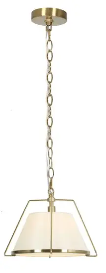
Introduction
Item Number: A04769
WARNING (To reduce the risk of fire, electric shock, or personal injury):
- We suggest installation by a licensed electrician.
- Please read the instruction carefully and save it as you may need it at a later time.
- Before you start, NEVER attempt any work without shutting off the electricity until the work is done.
- Go to the main fuse, or circuit breaker, box in your home.
Place the main power switch in the “OFF” position. - Place the wall switch in the “OFF” position.
- Go to the main fuse, or circuit breaker, box in your home.
- Mounting surface should be clean, dry, flat, strong enough and 1/4” larger than the canopy on all sides.
Any gaps between the mounting surface and canopy exceeding 3/16” should be corrected as required. - Make sure that the ceiling or wall can stand the weight of the lamp before installation.
- Make sure the voltage you are using is 120V. The maximum wattage is 40W per bulb.
- Keep the lamp away from acidic and alkaline substances in case of damaging the surface of the lamp.
- When replacing bulbs, you should turn off or unplug the lamp and you must wait until it is cool as bulbs get hot quickly.
- The safety instructions appearing in this manual are not meant to cover all possible conditions that may occur. It must be understood that common sense, caution and care must be used with any electrical products.
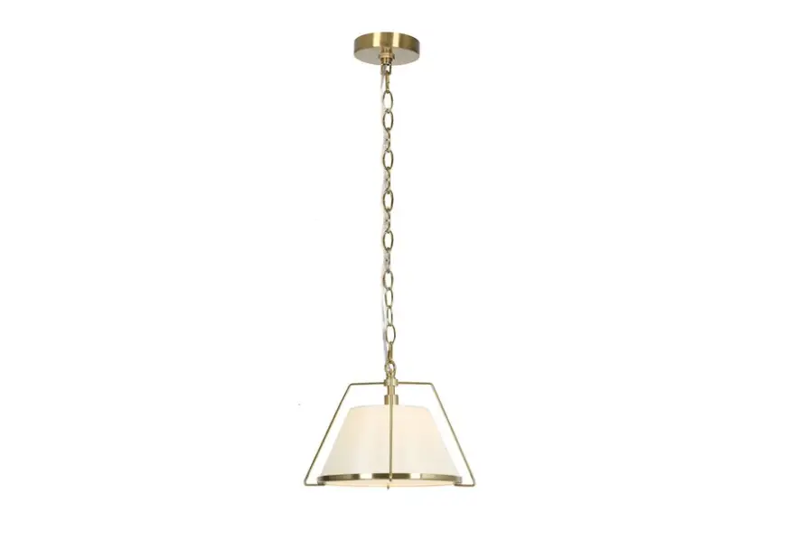
IMAGE FOR FINISHED PRODUCT: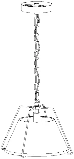
TOOLS REQUIRED (NOT INCLUDED):
 | 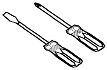 |  |  |  |
| Ladder | Phillips head. Flat blade screwdriver | Electric tape | Pliers | Wire cutter/Stripper |
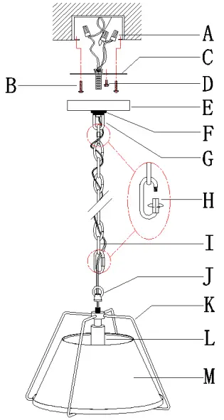
ACCESSORIES & QTY ENCLOSED:
- (A) Wire connector (3)
- (B) Mounting screw (2)
PARTS TYPE & QTY INCLUDING: - (C) Single bar (1)
- (D) Green ground screw (1)
- (E) Canopy (1)
- (F) Collar ring (1)
- (G) Collar loop (1)
- (H) Quick link (2)
- (I) Chain (1)
- (J) Loop (1)
- (K) Iron frame (1)
- (L) Socket (1)
- (M) Lampshade (1)

ASSEMBLY & INSTALLATION INSTRUCTIONS:
- Carefully remove the fixture from the carton and check that all parts and accessories are included as shown in the above illustration.
- Make pre installation
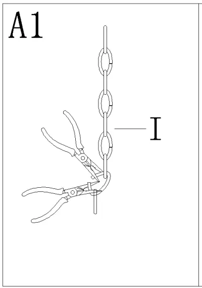
- Step A1
By measuring, determine the correct number of links needed for proper hanging height. Using the chain pliers, disconnect and discard the unwanted part.
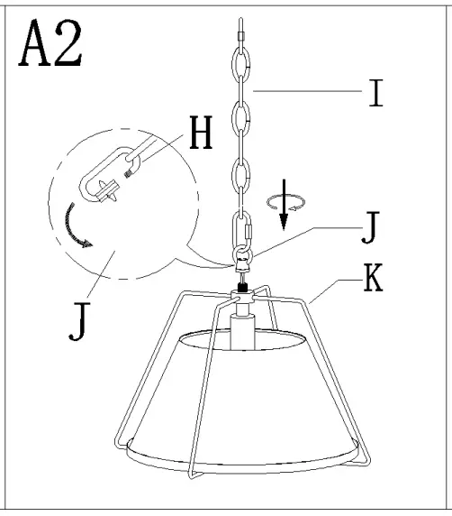
- Step A2
Screw loop (J) onto the top of iron frame (K).
Attach quick link (H) to chain (I) and loop (J) on the top of iron frame (K).
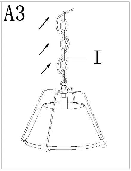
- Step A3
Carefully weave the fixture wires through chain (I) in and out of every other link and stop just when you reach the top of chain (I). Gently pull the wires to ensure the wires are not stressed.
- Step A1
- Turn off power
Before you start the installation, NEVER attempt any work without shutting off the electricity until the work is done.- Go to the main fuse, or circuit breaker, box in your home.
Place the main power switch in the “OFF” position. - Place the wall switch in the “OFF” position.
- Go to the main fuse, or circuit breaker, box in your home.
- Make installation
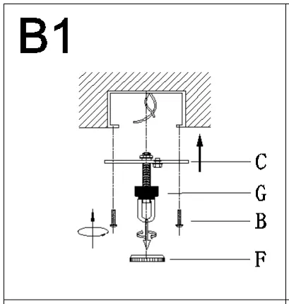
- Step B1
Remove collar ring (F) from collar loop (G). Attach single bar (C) to the outlet box with mounting screws (B).
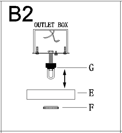
Note: the side of single bar (C) marked “GND” must face out. - Step B2
Raise canopy (E) over collar loop (G) and screw collar ring (F) to measure a proper position.
NOTE: canopy (E) should be snug against the ceiling and collar loop (G) should be screwed enough threads (no less than 6 threads) on the pre assembled threaded nipple for more secure hanging. If not, adjust collar loop (G) on single bar assembly (C) by screwing collar loop (G) in or out of single bar (C) until the secure length is achieved. - Step B3
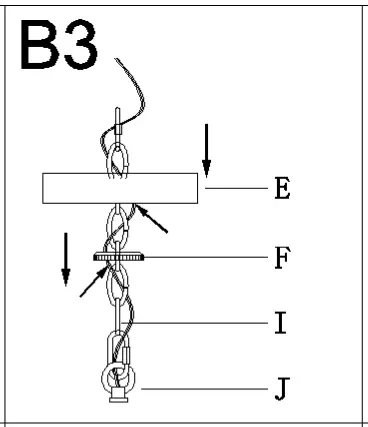
Pass chain (I) through collar ring (F) and then through canopy (E).
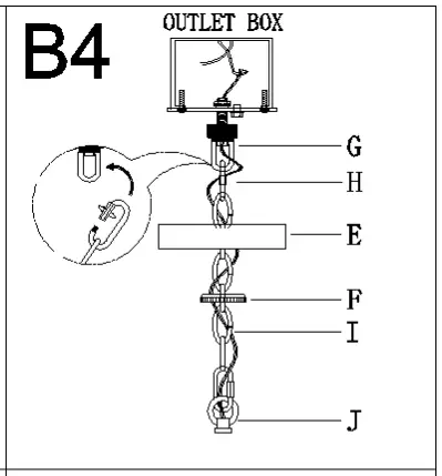
- Step B4
Open quick link (H), attach quick link (H) to collar loop (G). Close quick link (H).
Pass the fixture wires through collar loop (G) to the top of the preassembled threaded nipple and gently pull to ensure the wires are not stressed.
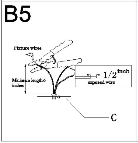
- Step B5
If needed, shorten the length of fixture wires. At this point, the remaining wire length measured above single bar (C) is at least 6″.
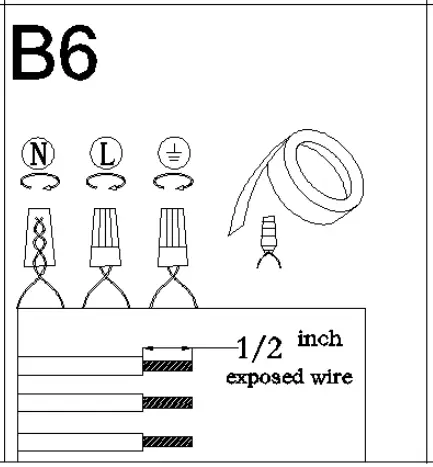
- Step B6
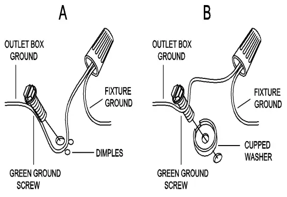
Make wire connections.
Connect wires as below wires connection shown.
PLEASE NOTE THAT GROUND WIRE IS BARE COPPER WIRE, NEVER CONNECT OTHER WIRES TO GROUND WIRES.
Connect ground wires according to the below chart
Connect wires according to the below chartConnect Black or Red Supply Wire to: Connect White Supply Wire to: Black White *Parallel cord ( round & smooth ) *Parallel cord ( square & ridged ) Clear, Brown, Gold or Black without tracer Clear, Brown, Gold or Black with tracer Insulated wire ( other than green ) with copper conductor Insulated wire ( other than green ) with silver Twist wires together with plastic wire connectors until tightly joined, and wrap each connector with approved electrical tape. Be sure that no wire strands are exposed and then carefully tuck all wires into the outlet box.
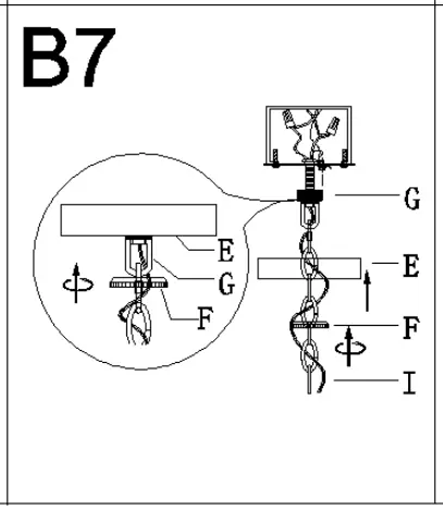
- Step B7
Raise canopy (E) to the ceiling and secure canopy (E) in place by tightening collar ring (F) onto collar loop (G).
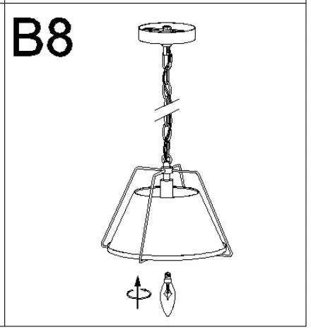
- Step B8
Install the bulb (not included) (Please do not exceed the maximum wattage recommended on the socket.)
- Step B1
- Check everything is already installed properly, then you could turn on the light. Enjoy!
ORDERING PARTS
Keep this sheet for future reference in case you need to order replacement parts. All parts for this fixture can be ordered from the place of purchase. Be sure to use exact wording from illustration when ordering parts.
CLEANING
To clean, wipe the fixture with a soft cloth. Do not use abrasive materials such as scouring pads or powders, steel wool or abrasive paper.
Customer Support
![]() +1 850 296 2377
+1 850 296 2377
Working hours: Mon Fri 9:00 16:00 EST![]() [email protected]
[email protected]


