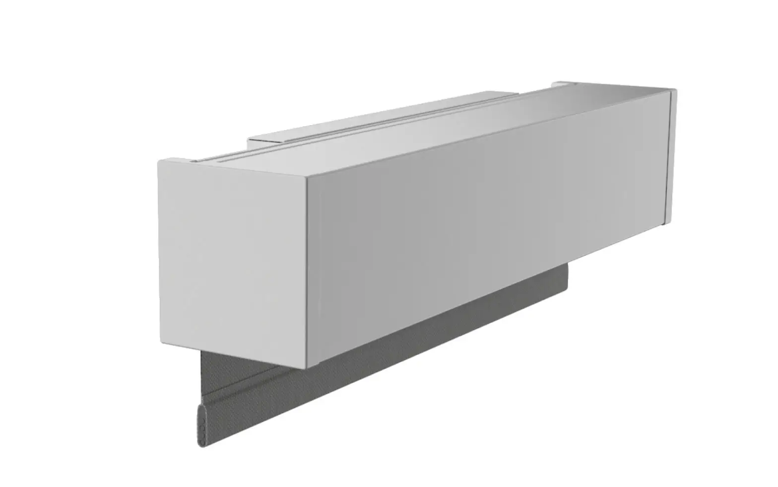
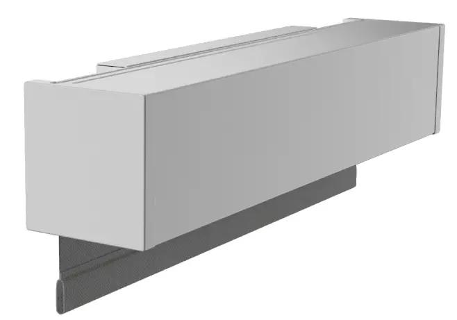
 Screen Innovations 24v DC – 485 Nano Box
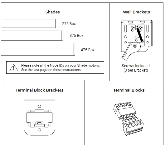
PARTS LIST – NANO BOX – 24v DC – 485
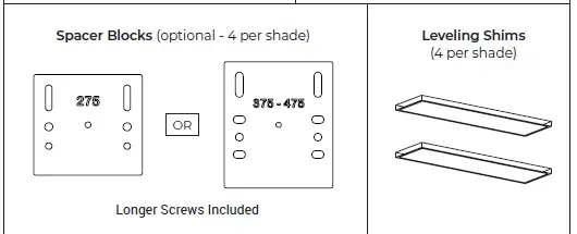
SPACER BLOCKS AND LEVELING SHIMS (OPTIONAL)
Spacer Blocks – used to clear an obstruction in the fabric path.
 Connect spacer blocks to shade brackets before installation. Note: Do not use more than 4 spacer blocks per bracket.
Leveling Shims – used if the window frame is out of level. 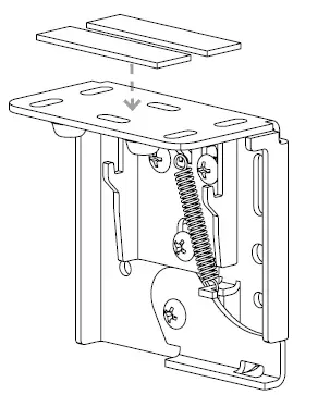 Connect to shade brackets before installation
Note: Do not use more than 2 leveling shims per bracket.
INSTALLATION – 24v DC – 485
Terminate pre-wire with the supplied terminal block.
 Box bracket position is recommended 2”-4” from end caps.
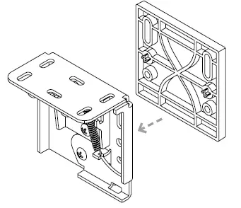
 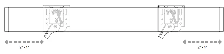 Make sure the wall bracket lever is down (may already be down).
 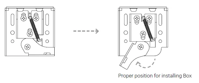 Install terminal block bracket between jamb and wall bracket on the motor side using the supplied screws
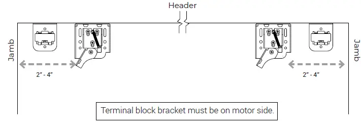 Connect the shade and pre-wire connectors, then snap into the terminal block bracket
 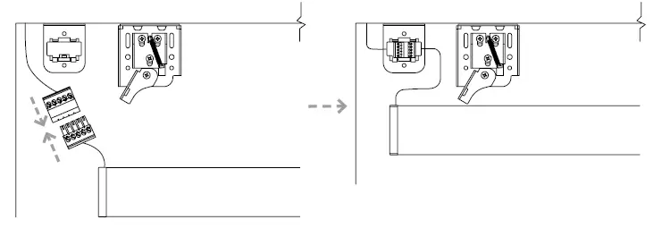 Hang shade onto wall brackets and center in opening
 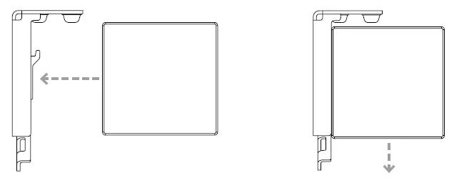 Use thumb to lock shade in place
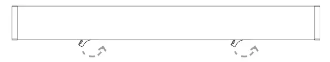
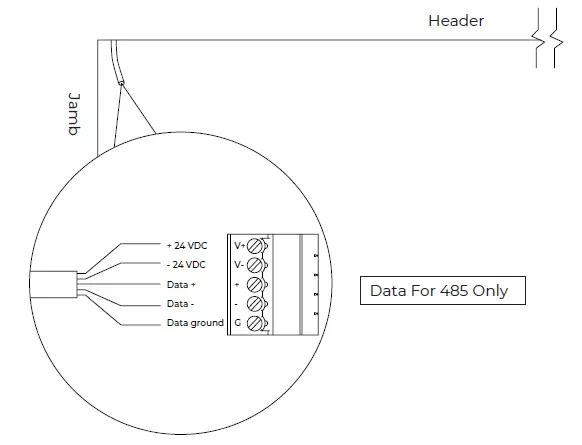
WIRING – 485
24v DC – Using 5 Conductor Wire
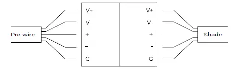
| Marking | Description |
| V+ | Positive 24VDC |
| V- | Negative 24VDC |
| + | 485 Data Positive |
| – | 485 Data Negative |
| G | 485 Data Ground |
| Wire Gauge (AWG) | Maximum Supported Wire Length (FT.) |
| 14 | 250 |
| 16 | 150 |
| 18 | 100 |
24v DC – Using UTP wire
Wire between Janus terminal block face and the motor only.
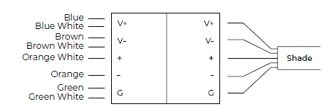
| Marking | Description |
| V+ | Positive 24VDC |
| V- | Negative 24VDC |
| + | 485 Data Positive |
| – | 485 Data Negative |
| G | 485 Data Ground |
| Wire Gauge (AWG) | Supported Wire Length (FT.) |
| 24 w/o Spike | 150 (275 Shade) 100 (375 Shade) |
| 24 w Spike | 300 (275 Shade) 150 (375 Shade) |
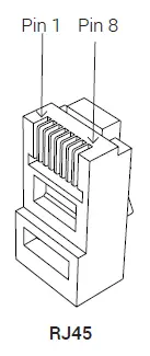
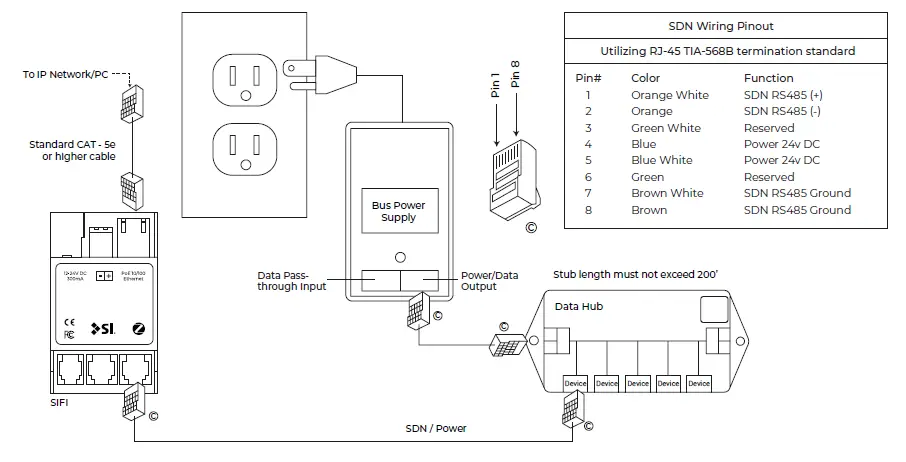
RJ45 DATA CABLE FOR DATA HUB ONLY
If the shade will be connected to a Data Hub or Power Panel device port for data, terminate with the following pinout:
| 485 Wiring Port | ||
| Utilizing RJ-45 TIA-568B termination standard | ||
| Pin# | Color | Function |
| 1 | Orange White | 485 (+) |
| 2 | Orange | 485 (-) |
| 3 | Green White | Reserved |
| 4 | Blue | Power 24v DC (V+) |
| 5 | Blue White | Power 24v DC (V+) |
| 6 | Green | Reserved |
| 7 | Brown White | 485 Ground (G) |
| 8 | Brown | 485 Ground (G) |
| For Shade Data, use Pins 1, 2 & 8 | ||
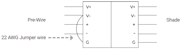
TERMINATION FOR 4 – CONDUCTOR THIRD PARTY CABLE
If the pre-wire does not have a third insulated data conductor for the 485 ground, terminate the wire as shown below. Use the same termination on both ends.
PROGRAMMING – 485
485 shades are programmed using the Screen Innovations SIFI via the web interface. This programming can be done with a Windows or Mac computer either over LAN or wired directly to SIFI. The following instructions are for a Windows computer, but the steps for programming on a Mac are very similar. For a complete guide to program SIFI on a Mac, please visit our website. Before attempting to program any motors with SIFI, verify that the firmware is up to date. To adjust the lower limit of an 485 shade, follow the steps below.
Connect SIFI as shown below.
- Launch Windows File Explorer
- Click on the “Network” tab
- Double click on the SIFI, the default web browser will launch
- At the landing page, click the three lines in the top right corner, then click “Settings”
- Select the “485” tab on the top left
- Press the spyglass to auto discover motors on the 485 network (may have to press it more than once)
- Click on the motor you want to program
- Name the motor
- Right click on the down limit count
- Move the shade up or down using the buttons in the popup window
- Click set to confirm the limit
- Operate the shade up and then back down to verify the position of the limit
TROUBLESHOOTING – 485
| Problem | Possible Cause | Action to Take | |
| Shade won’t operate. | Motor is not powered. | Ensure that 24Volt motors have 24v DC supply and that the polarity is correct. | |
| Incorrect or poor cable termination. | Check the wire pinouts and termination. Look for broken, loose, or damaged wires. Reterminate if necessary. | ||
| SIFI is not powered. | Check that the green LED on SIFI is flashing. If not, make sure power is available via the bus power supply or PoE (with expansion card only). | ||
| SIFI is not on the local network. | Use the service keypad (if available) to validate the 485 network and motors are operating properly before troubleshooting SIFI network problems. Check that the SIFI is communicating on the local network. Ping the device via the windows command prompt, or make sure the device shows up in the network tab of the Windows File Explorer. | ||
| Please use this QR Code to access the updated installation instructions and related documents. | Technical Support: 512.832.6939 screeninnovations.com Hours of Support: 7:30am – 5pm CST [email protected] | ||
NODE IDS
Please keep a note of all the Node IDs on your shade motors. OR for larger shade orders, refer to your Sales Order document for the list.
Screen Innovations
9715-B Burnet Rd, Suite 400 Austin, TX 78758 512.832.6939
www.screeninnovations.com


