![]()
MANEX7xxMU002 V.1.02 20.12.2022
eX7xxM
Installation guide
DIMENSION-CUT OUT
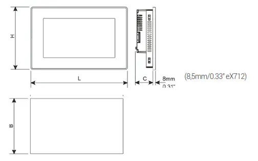
| Model | A | B | C | H | L |
| eX707M | 176mm/06.90″ | 136mm/05.35″ | 47mm/01.85″ | 147mm/05.79″ | 187mm/07.36″ |
| eX710M | 271mm/10.66″ | 186mm/07.32″ | 56mm/02.20″ | 197mm/07.75″ | 282mm/11.10″ |
| eX712M | 332,5mm/13.09″ | 151 mm/05.94″ | 49mm/01.92″ | 163mm/06.41″ | 344,5mm/13.16″ |
| eX715M | 411mm/16.18″ | 256mm/10.00″ | 56mm/02.20″ | 267mm/10.50″ | 422mm/16.60″ |
| eX721 M | 541mm/21.30″ | 336mm/13.22″ | 56mm/02.20″ | 347mm/13.66″ | 552mm/21.73″ |
| Model | CSD | CSD2 |
| eX707M | 850mm/33.46″ | 400mm/15.75″ |
| eX710M | 1150mm/45.28″ | 750mm/29.53″ |
| eX712M | 400mm/15.75″ | 100mm/03.93″ |
| eX715M | 1800mm/70.87″ | 1300mm/51.18″ |
| eX721 M | 2200mm/86.61″ | 1300mm/51.18″ |
FIXING BRACKE
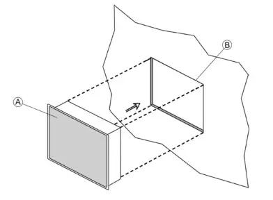
A) eX7xxM
B) Cut-out on a flat surface (min wall thickness 1.2mm)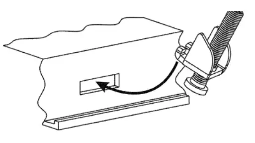
![]() Tightening torque: 130Ncm±5Ncm or screw each fixing screw until the bezel corner gets in contact with the panel.
Tightening torque: 130Ncm±5Ncm or screw each fixing screw until the bezel corner gets in contact with the panel.
REAR VIEW
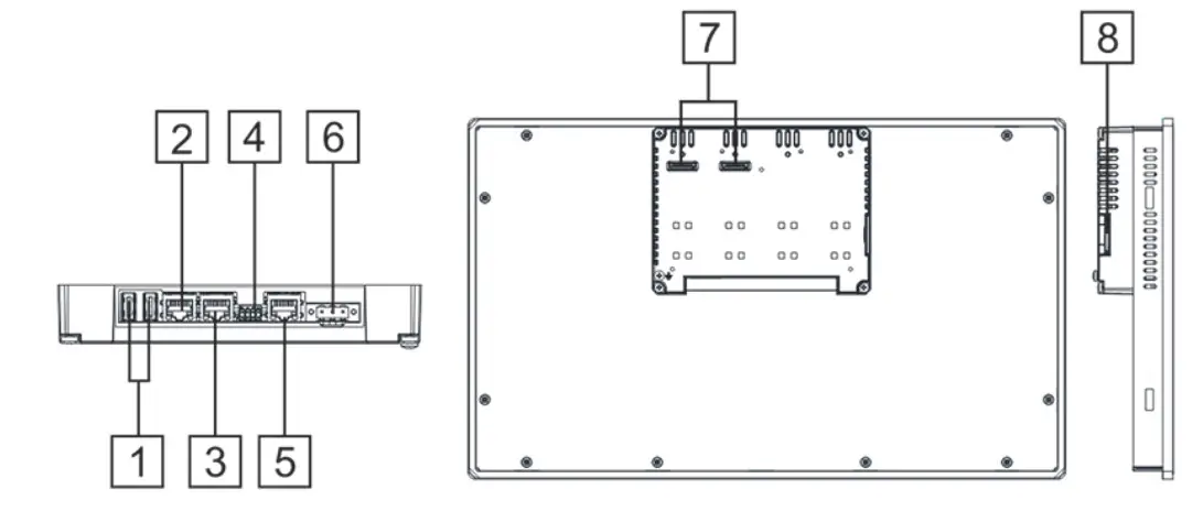
| Description | |
| 1 | USB port V2.0, max. 500 mA |
| 2 | Ethernet port 2 (10/100 Mb) |
| 3 | Ethernet port 1 (10/100 Mb) |
| 4 | Serial port |
| 5 | Ethernet port 0 (10/100/1000 Mb) |
| 6 | Power supply |
| 7 | 2 Expansion slots for plugin modules |
| 8 | SD Card Slot |
| * for maintenance only only | |
![]() All ports are SELV (Safety Extra – Low Voltage) according European Standards and Class 2 according UL Standards
All ports are SELV (Safety Extra – Low Voltage) according European Standards and Class 2 according UL Standards![]() WARNING – EXPLOSION HAZARD – (Ethernet, USB connectors, memory card slot) DO NOT CONNECT OR DISCONNECT UNLESS THE POWER HAS BEEN DISCONNECTED OR THE AREA IS KNOWN TO BE FREE OF IGNITABLE CONCENTRATIONS.
WARNING – EXPLOSION HAZARD – (Ethernet, USB connectors, memory card slot) DO NOT CONNECT OR DISCONNECT UNLESS THE POWER HAS BEEN DISCONNECTED OR THE AREA IS KNOWN TO BE FREE OF IGNITABLE CONCENTRATIONS.![]() Don’t open the panel rear cover when the power supply is applied.
Don’t open the panel rear cover when the power supply is applied.
POWER SUPPLY
![]() Extra low voltage power supply / Limited power source.
Extra low voltage power supply / Limited power source.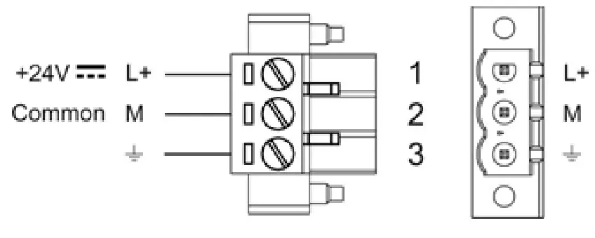 DC Power Connector, Female – R/C Terminal Blocks (XCFR2), manufactured by Weid muller Inc., Cat. No. BLZ 5.08, torque 4.5 lb-in
Do not open the cabinet while the system is powered up.![]() WARNING: Do not separate when energized.
WARNING: Do not separate when energized.
The unit must always be grounded to earth with 1.5mmq wire size minimum. Earth connection will have to be done using either the screw or the faston terminal located near the power supply terminal block. Also connect to ground the terminal 3 on the power supply terminal block. All the electronic devices in the control system must be properly grounded. Grounding must be performed according to applicable regulations.
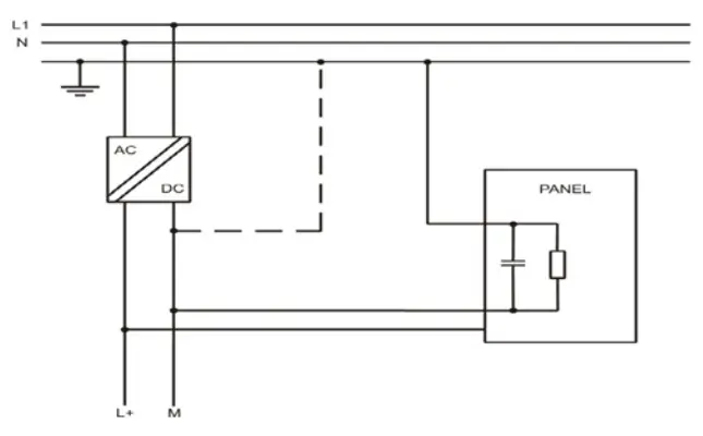
![]() Ensure that the power supply has enough power capacity for the operation of the equipment.
Ensure that the power supply has enough power capacity for the operation of the equipment.
CONNECTIONS

To operate in RS-485 pins 1-2 and 4-3 must be connected externally
| PIN | Description |
| 1 | RX/CHB- |
| 2 | TX/CHA- |
| 3 | CTS/CHB+ |
| 4 | RTS/CHA+ |
| 5 | +5V output |
| 6 | GND |
| 8 | SHIELD |
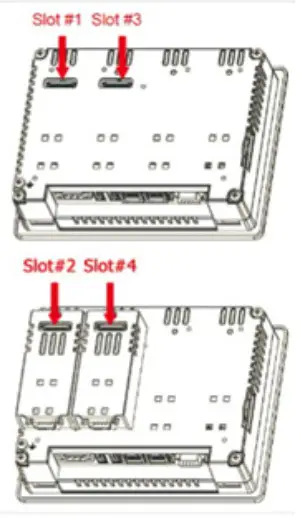
EXPANSION SLOT FOR PLUG-IN MODULES
The validity of UL certification is ensured only by using accessories (PLxx) covered by the same certificate.
DISPOSE OF BATTERIES
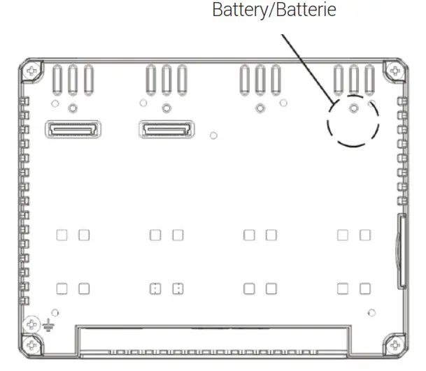
![]() These devices are equipped with rechargeable Lithium battery, not user-replaceable.
These devices are equipped with rechargeable Lithium battery, not user-replaceable.![]() Dispose of batteries according to local regulations.
Dispose of batteries according to local regulations.![]() This device cannot be disposed of as a domestic waste but accord- ing to WEEE European Directive 2012/19/EU
This device cannot be disposed of as a domestic waste but accord- ing to WEEE European Directive 2012/19/EU
USAGE IN EXPLOSION-HAZARDOUS AREAS ZONE 2 AND ZONE 22
![]() The connection and installation have to be done in conformity with ATEX Directive, IEC EN 60079-14, and have to be performed by authorized, qualified personnel and in possession of necessary skills.
The connection and installation have to be done in conformity with ATEX Directive, IEC EN 60079-14, and have to be performed by authorized, qualified personnel and in possession of necessary skills.![]() Confirm that the location is free from explosively hazardous gases or dust beforeconnecting or disconnecting equipment, replacing or wiring modules. Confirm that thepower supply has been turned OFF before disconnecting, replacing or wiring modules.
Confirm that the location is free from explosively hazardous gases or dust beforeconnecting or disconnecting equipment, replacing or wiring modules. Confirm that thepower supply has been turned OFF before disconnecting, replacing or wiring modules.![]() Before turning ON, clean the front panel of the graphic panel with a damp cloth to avoid any electrostatic discharge.
Before turning ON, clean the front panel of the graphic panel with a damp cloth to avoid any electrostatic discharge.![]() The graphic panel must not be exposed to direct sunlight.
The graphic panel must not be exposed to direct sunlight.
The vents in the panel casing must not be obstructed.
Do not allow layers of dust to form on the graphic panel: it should be cleaned regularlymaking clean with a damp cloth.
Check that graphic panels are mounted in enclosures satisfying minimum IP54 degree ofprotection for category 3G and IP6x for category 3D and the requirements relating to the 3Gor 3D categories in Zones 2/22 (Category 3: normal level of protection – G: Gas – D: Dust).![]() End User is responsible to ensure that the maximum operating temperature is not exceeded in the end use application
End User is responsible to ensure that the maximum operating temperature is not exceeded in the end use application![]() Ensure that the labelling specifications are compatible with the conditions permitted for the hazardous area at the site where it is being used (Zones 2/22 Group II: Surface industries – Category 3: Normal level of protection – G: Gas – D: Dust – IP: degree of protection (protection against solids and liquids) – T: maximum surface temperature).
Ensure that the labelling specifications are compatible with the conditions permitted for the hazardous area at the site where it is being used (Zones 2/22 Group II: Surface industries – Category 3: Normal level of protection – G: Gas – D: Dust – IP: degree of protection (protection against solids and liquids) – T: maximum surface temperature).
ATEX markings, apllied to the Models
DEMKO 17 ATEX 1871X / UL22UKEX2726X
II 3G Ex ec IIC T5…T4 Gc 0°C≤Tamb≤+50°C or -20°C≤Tamb≤+60°C
II 3D Ex tc IIIC T95°C Dc
T Amb: 0°C – +50°C or -20°C – +60°C
Type examination certificate number:![]() DO NOT DISCONNECT WHILE CIRCUIT IS LIVE
DO NOT DISCONNECT WHILE CIRCUIT IS LIVE
IECEx markings, apllied to the Models
IECEx: IECEx ULD 17.0019X
Ex ec IIC T5…T4 Gc 0°C≤Tamb≤+50°C or -20°C≤Tamb≤+60°C Ex tc IIIC T95°C Dc
Type examination certificate numbe
The products have been designed for use in an industrial environment in compliance with the 2014/30/EU directive
Software available in these products is based on OpenSource. Visit oss.exorint.net for more details.
The products have been designed in compliance with
| EN 61000-6-4 | EN 61000-4-3 |
| EN 61000-6-2 | EN 61000-4-4 |
| EN 60945 | EN 61000-4-5 |
| EN 60079-0 | EN 61000-4-6 |
| EN 60079-7 | EN 61000-4-8 |
| EN 60079-31 | EN 61000-4-11 |
| EN 61000-4-2 | EN 61000-4-29 |
Equipment group II, category 3 intended for use in potentially explosive atmospheres zones
2/22, G:gas and D:dust.
Type examination certificate number
DEMKO 17 ATEX 1871 / UL22UKEX2726X
The installation of these devices into the residential, commercial and light-industrial environments is allowed only in the case that special measures are taken in order to get the conformity to IEC-61000-6.3.
WARNING – Power, input and output (I/O) wiring must be in accordance with Class I, Division 2 wiring methods, Article 501.10 (B) of the National Electrical Code, NFPA 70 for installation in the U.S., or as specified in Section 18-1J2 of Canadian Electrical Code for installations within Canada and in accordance with the authority having jurisdictions.
A. WARNING – EXPLOSION HAZARD – SUBSTITUTION OF ANY COMPONENT MAY IMPAIR SUITABILITY FOR CLASS I, DIVISION 2
B. WARNING – EXPLOSION HAZARD – WHEN IN HAZARDOUS LOCATIONS, TURN OFF OWER BEFORE REPLACING OR WIRING MODULES, and
C. WARNING – EXPLOSION HAZARD – DO NOT DISCONNECT EQUIPMENT WHILE THE CIRCUIT IS LIVE OR UNLESS THE AREA IS KNOW TO BE FREE OF IGNITABLE CONCENTRATIONS.
D. SUITABLE FOR USE IN CLASS I, DIVISION 2, GROUPS A, B, C AND D HAZARDOUS LOCATIONS, OR NONHAZARDOUS LOCATIONS ONLY.
E. WARNING – EXPLOSION HAZARD – DO NOT CHANGE BATTERY UNLESS THE AREA IS KNOWN TO BE FREE OF IGNITABLE CONCENTRATIONS
F. This equipment, except for the front panel display, is an open-type device and is required to be installed in an enclosure suitable for the environment such that the internal part of the equipment is only accessible with the use of a tool.
STANDARDS AND APPROVALS
| IECEx | IECEx: IECEx ULD 17.0019X |
| IEC 60079-0 | Ex ec IIC T5…T4 Gc 0°C≤Tamb≤+50°C or -20°C≤Tamb≤+60°C |
| IEC 60079-7 | Ex tc IIIC T95°C Dc |
| IEC 60079-31 | |
| ATEX | DEMKO 17 ATEX 1871X / UL22UKEX2726X |
| EN 60079-0 | II 3G Ex ec IIC T5…T4 Gc 0°C≤Tamb≤+50°C or -20°C≤Tamb≤+60°C |
| EN IEC 60079-7 + A1 | II 3D Ex tc IIIC T95°C Dc |
| CENELEC EN 60079-31 | |
SPECIAL INSTRUCTION FOR USE
- For EPL Gc,
– the equipment shall only be used in an area of at least pollution degree 2, as defined in IEC/ EN 60664-1.
– the equipment shall be installed through an end-equipment enclosure that provides a minimum ingress protection of IP54 in accordance with IEC/EN 60079-0, suitable for applicable Gas Group, Temperature Classification and Ambient temperature range; and
– transient protection shall be provided that is set at a level not exceeding 140% of the peak rated voltage value at the supply terminals to the equipment. - For EPL Dc, the equipment shall be installed through an end-eqipment enclosure that provides a minimum ingress protection of IP6X in accordance with IEC/EN 60079-0, suitable for applicable Dust Group, Temperature Classification and Ambient temperature range.
- Care shall be taken not to allow layers of dust to form on the graphic panel in a way that might cause the accumulation of static charges.
- eX700 series have only been evaluated for low risk of mechanical impact.
The relation between maximum ambient temperature and the assigned temperature class is as follow:
| Maximum Ambient Temperature Range | Temperature Class |
| -20°C up to 60°C | T4 |
| 0°C up to 50°C | T5 |
Ambient temperature range: the ambient temperature range is –20°C≤Tamb≤+60°C.
The ambient temperature range is limited to 0°C≤Tamb≤+50°C when installed with plug-in module, model PLIO03 with Part Number PLIO03xxxxY with Y≤2.
TECHNICAL DATA
| All models / Alle Modelle | |
| Display/Backlight | TFT Color / LED |
| Colors | 16M |
| Dimming | yes |
| SD card slot | yes |
| Serial Port | RS-232,RS-485, RS-422 Software configurable |
| Ethernet port | 2 10/100Mb, 1 10/100/1000Mb |
| USB port | 2 Host interface version 2.0 max. 500mA |
| Expansion slot | 2 Optional Plugin |
| Battery | rechargeable |
| Real Time Clock | yes |
| Voltage | 24Vdc |
| eX707M | eX710M | eX712M | |
| Resolution | 800X480 | 1280X800 | 1920X720 |
| Diagonal (inches) | 7′ widescreen | 10.1’widescreen | 12.3″ widescreen |
| User memory flash | 4GB | 4GB | 8GB |
| Recipe memory | 1GB | 1GB | 2GB |
| Current rating 24VDC | 0.7A | 1.00A | 1.10A |
| Weight | 1.3 Kg | 1.7 Kg | 1.8 Kg |
| eX715M | eX721M | |
| Resolution | 1366X768 | 1920X1080 |
| Diagonal (inches) | 15.6 widescreen | 21.5Widescreen |
| User memory flash | 8GB | 8GB |
| Recipe memory | 2GB | 2GB |
| Current rating 24VDC | 1.2A | 1.7A |
| Weight | 4.1 Kg | 6.1 Kg |
PRODUCT IDENTIFICATION
The product may be identified through a plate attached to the rear cover. You will have to know the type of unit you are using for correct usage of the information contained in the guide. An example of this plate is shown in the figure below:
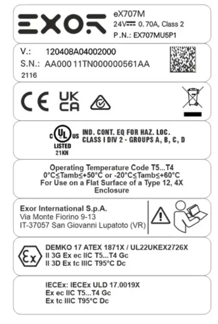
| product model name | eX707M |
| product part number | EX707MU5P1 |
| year/week of production | 2116 |
| serial number | AA00011TN000000561AA |
| version id of the product | 120408A04002000 |
| manufacturer address and | Exor International S.p.A. |
| read instruction warning | Via Monte Fiorino 9-13 IT-37057 San Giovanni Lupatoto (VR) |
| ATEX Marking | DEMKO 17 ATEX 1871X / UL22UKEX2726X II 3G Ex ec IIC T5…T4 Gc 0°C≤Tamb≤+50°C or -20°C≤Tamb≤+60°C II 3D Ex tc IIIC T95°C Dc |
| IECEx Marking | IECEx: IECEx ULD 17.0019X Ex ec IIC T5…T4 Gc 0°C≤Tamb≤+50°C or -20°C≤Tamb≤+60°C Ex tc IIIC T95°C Dc |
MODULE PLUGIN OPTIONNEL
IDENTIFICATION DU PRODUIT
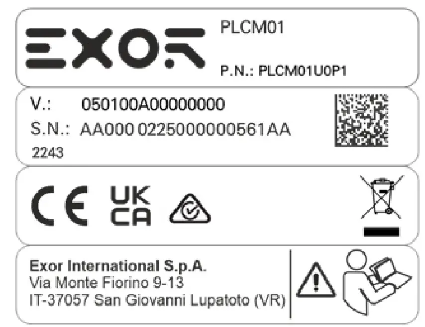
| product model name | PLCM01 |
| product part number | PLCM01U0P1 |
| year/week of production | 2243 |
| serial number | AA0000225000000561AA |
| version id of the product | 050100A00000000 |
| manufacturer address and read | Exor International S.p.A. |
| instruction warning | Via Monte Fiorino 9-13 IT-37057 San Giovanni Lupatoto (VR) |
INSTALLATION PROCEDURE
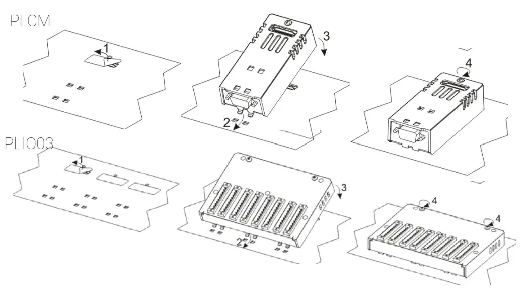
| Application | Max modules | Connecteur | |
| PLCM01 | CAN | 2 | Y |
| PLCM01-NE | CAN | 2 | N |
| PLCM05 | CODESYS License | 1 | Y |
| PLCM09X | 3G Modem | 1 | Y |
| PLIO03 | Multifunction I/O | 1 | N |
| PLCM01 / PLCM01-NE | Operating temperature -20°C to 60°C |
| PLCM05 | Operating temperature -20°C to 60°C |
| PLCM09X | Operating temperature -20°C to 60°C |
| PLIO03* | with part number PLIO03xxxxY where: – Y≤2 is operating temperature range 0°C≤Tamb≤+50°C with Operating Temperature Code T5 (vertical installation), 12-30VDC – Y>2 is operating temperature range –20°C≤Tamb≤+60°C with Operating Temperature Code T4 (vertical installation), 12-30VDC |
![]() PLCM and PLIO03 electrical ratings:
PLCM and PLIO03 electrical ratings:
– PLCM01: For electrical rating refers to the host eX700 models.
– PLCM05: For electrical rating refers to the host eX700 models and PLIO03 ratings
– PLCM09X: 2xDigital Inputs voltage 12÷30 Vdc, 3mA; 2xDigital Outputs voltage 12÷30 Vdc, 0.5A
– PLIO03: 20xDigital Inputs voltage 12÷30 Vdc; 12xDigital Outputs voltage 12÷30 Vdc, 0.5A; 4xAnalog inputs 0÷10 Vdc, 4-20mA; 4xAnalog outputs: 0÷10 Vdc, 4-20mA
Reproduction of the contents of this copyrighted document, in whole or part, without written permission of Exor International S.p.A., is prohibited.
User Manual available on
www.exorint.com
MANEX7xxMU002 V.1.02 20.12.2022
© 2020-2022 Exor International S.p.A
Exor International S.p.A. – San Giovanni Lupatoto VR, Italy www.exorint.com
MANEX7xxMU002 V.1.02 20.12.2022
© 2020-2022 Exor International S.p.A
Exor International S.p.A. – San Giovanni Lupatoto VR, Italy
www.exorint.com


 User Guide")


