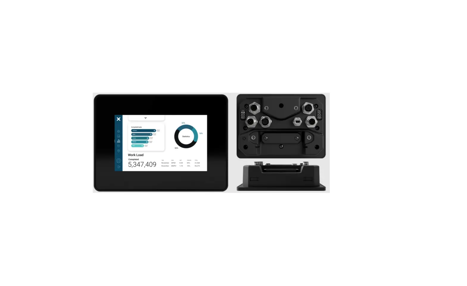
EXOR XA5 Outdoor HMI 5” PCAP Touch Sunlight-Readable Installation Guide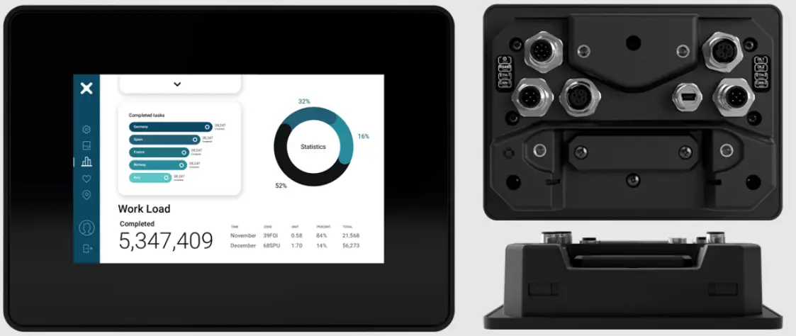
DIMENSION DIMENSION
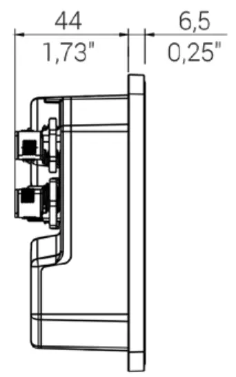
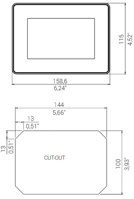
PANEL MOUNTING MONTAGE
Fixing bracket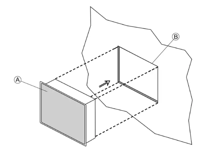
A) XA5
B) Cut-out on a flat surface (min wall thickness 1.2mm)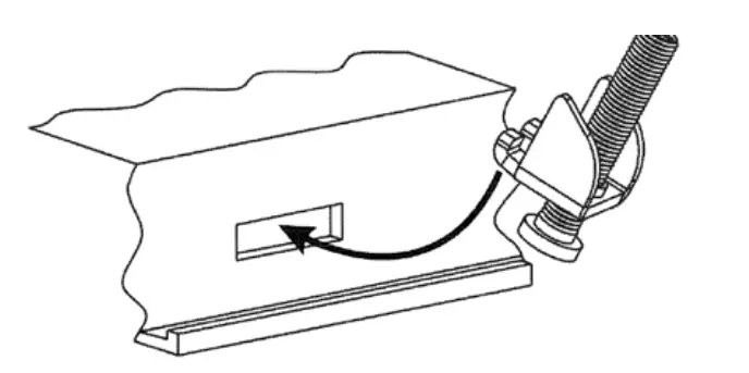
pieces
![]() Tightening torque: 130 Ncm ± 5 Ncm A
Tightening torque: 130 Ncm ± 5 Ncm A
ARM MOUNTING MONTAGE DU BRAS
AMPS Standard Fixing AMPS Standard
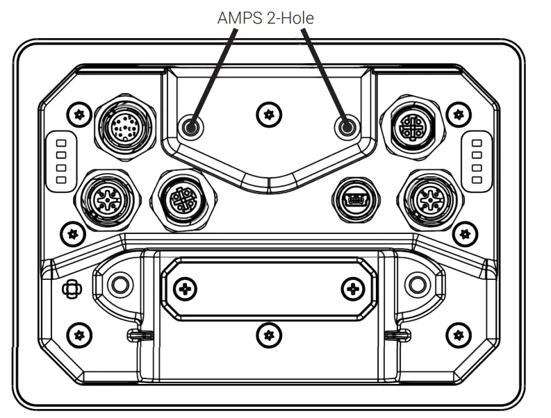
Suggestion Diamond Ball Base RAM-B-238U
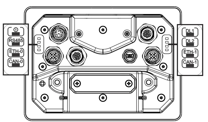
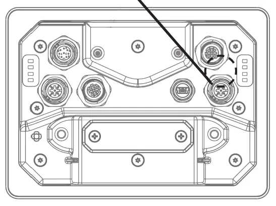
CONNECTIONS
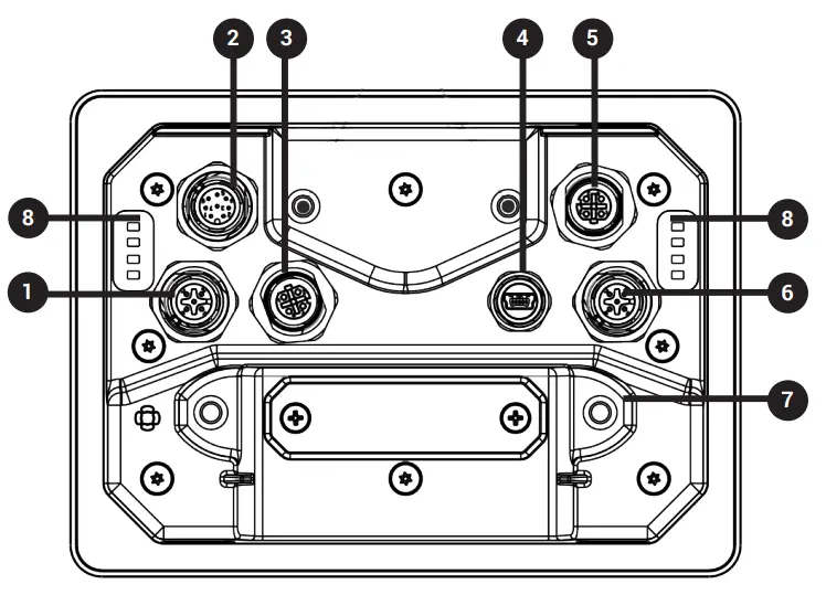
| 1 | CAN Port 0 |
| 2 | Power supply |
| 3 | Ethernet Port 0 (10/100 Mb) |
| 4 | USB Port V2.0 max 500 mA |
| 5 | Ethernet Port 1 (10/100 Mb) |
| 6 | CAN Port 1 |
| 7 | Expansion slot for plugin modules/ Plug-in-Module/ Emplacement d’extension pour les modules plug-in/ Slot-in |
| 8 | LED |
LED
POWER SUPPLY
![]() Extra low voltage power supply Limited power source.
Extra low voltage power supply Limited power source.
![]() Don’t open the device rear cover when the power supply is applied. sous tension. Non.
Don’t open the device rear cover when the power supply is applied. sous tension. Non.
24VDC supplied by SELV, limited energy source
![]() Ensure that the power supply has enough power capacity for the operation of the equipment.
Ensure that the power supply has enough power capacity for the operation of the equipment.
CONNECTIONS
CAN PORT M12-5 A coded
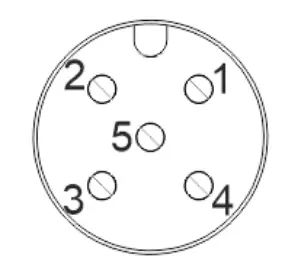
PIN | DESCRIPTION |
| 1 | SHIELD |
2 | |
| 3 | CAN_GND |
4 | CAN-H |
| 5 | CAN-L |
Suggestion
1694305 PHOENIX CONTACT
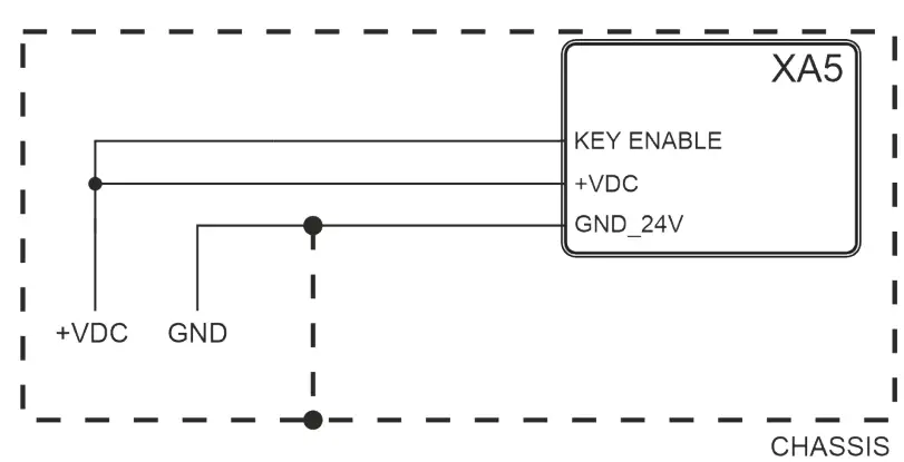
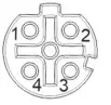
POWER SUPPLY
M12-8 A coded
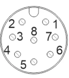
PIN | DESCRIPTION |
| 1 | +VDC |
2 | GND_24V |
| 3 | SSR |
4 | SSR |
| 5 | RS-485_CHA+ |
6 | RS-485_CHA- |
| 7 | KEY ENABLE |
8 | RS-485_GND |
SSR RELAY OUTPUT | |
| Output channels type | SPST-NO |
Load | 300mA Max |
| Max switching voltage | 40V |
Isolation | 500V |
Suggestion Suggestion
1511860 PHOENIX CONTACT
USB PORT
M12-USB type B-mini Female
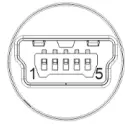
PIN | DESCRIPTION |
| 1 | Vcc |
2 | D- |
| 3 | D+ |
4 | |
| 5 | GND |
Suggestion Suggestion
1420168 PHOENIX CONTACT
ETH PORT
M12-4 D code
PIN | DESCRIPTION |
| 1 | TX+ |
2 | RX+ |
3 | TX- |
4 | RX- |
DISPOSE OF BATTERIES
Battery
These devices are equipped with rechargeable Lithium battery, not user-replaceable.
![]() Dispose of batteries according to local regulations.
Dispose of batteries according to local regulations.
AMBIENT LIGHT SENSOR
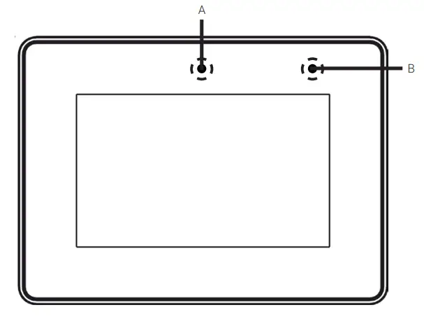
A – Ambient light Sensor
B – User configurable LED configurable par LED configurable
ANTENNA POSITION
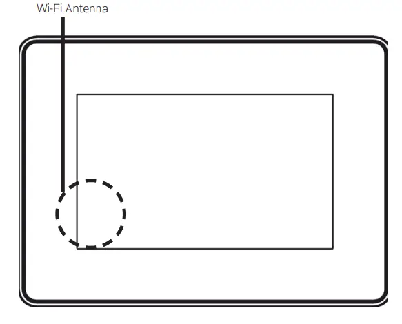
The WiFi antenna is positioned behind the left side band, behind the display.
The products have been designed for use in industrial environment in compliance with
the 2014/53/EU, 2011/65/EC directives
EN 61000-6-4: EN 61000-6-2
ETSI EN 301 489-1: ETSI EN 301 489-17
ETSI EN 300 328 : EN 62311
EN 61010-1 : EN 61010-2-201
The installation of these devices into the residential, commercial and light-industrial
environments is allowed only in the case that special measures are taken in order to get
the conformity to IEC61000-6-3. Die Installation
Reproduction of the contents of this copyrighted document, in whole or part, without written permission of Exor International S.p.A., is prohibited. fins International S.p.A. Se International S.p.A. International S.p.A.,
User Manual available www.exorint.com
MANXA5U001_V V.1.02 28.06.2022
©2022 Exor International S.p.A
Exor International S.p.A. – San Giovanni Lupatoto VR, Italy www.exorint.com


