![]()
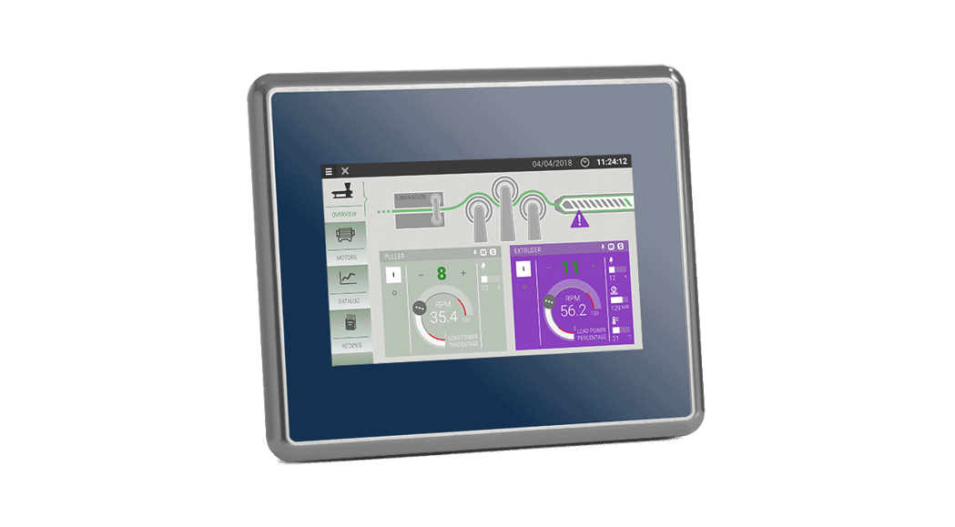
EX715MG Control Panel for Extreme Conditions
Installation Guide
EX715MG
Installation guide
DIMENSION-CUT OUT
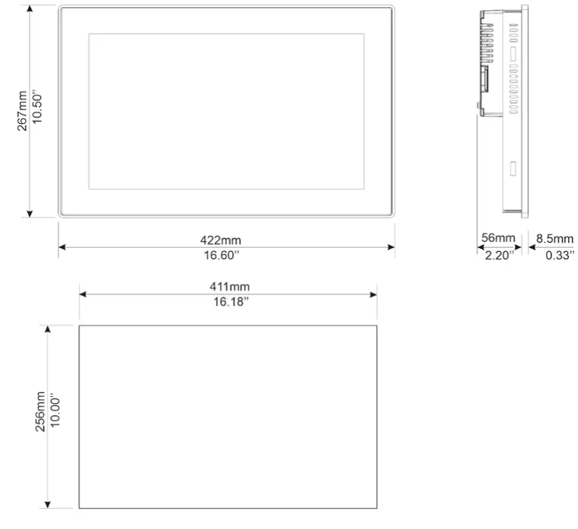
CSD = 850mm/33.46” Minimum Compass Safe Distance of the standard compass
FIXING BRACKET
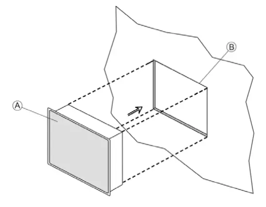
A) eX715MG
B) Cut out on a flat surface (min wall thickness 1.2mm)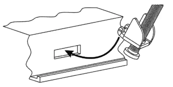
12 pieces![]() Tightening torque: 130Ncm or screw each fixing screw until the bezel corner gets in contact with the panel.
Tightening torque: 130Ncm or screw each fixing screw until the bezel corner gets in contact with the panel.
REARVIEW
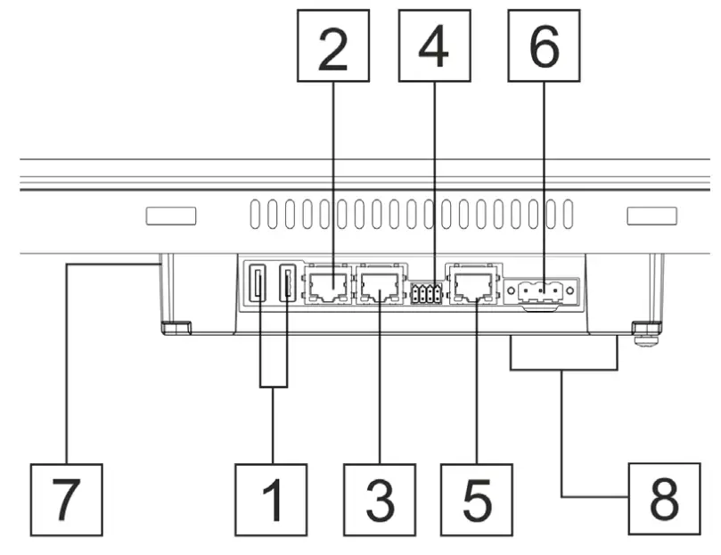
| Description | |
| 1 | USB port V2.0, max. 500 mA |
| 2 | Ethernet port 2 (10/100 Mb) |
| 3 | Ethernet port 1 (10/100 Mb) |
| 4 | Serial port |
| 5 | Ethernet port 0 (10/100/1000 Mb) |
| 6 | Power supply |
| 7 | SD Card Slot |
| 8 | 2 Expansion slots for plugin modules |
![]() All ports are SELV (Safety Extra – Low Voltage).
All ports are SELV (Safety Extra – Low Voltage).
POWER SUPPLY
![]() Extra low voltage power supply
Extra low voltage power supply 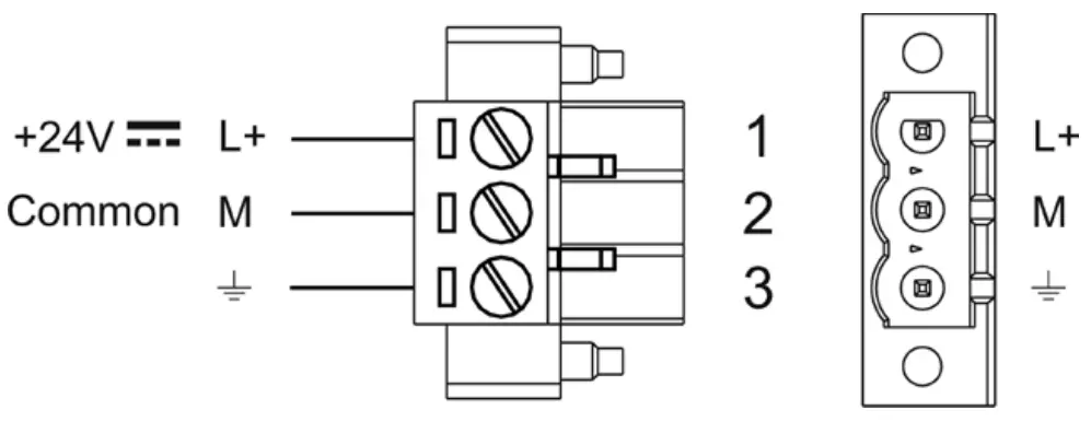
DC Power Connector, Female – R/C Terminal Blocks (XCFR2), manufactured by Weidmuller Inc., Cat. No. BLZ 5.08, torque 4.5 lb-in
3 conductor 1,5mmq wire size minimum, minimum temperature conductor rating 105°C.
Don’t open the panel rear cover when the power supply is applied.![]() WARNING: Do not separate when energized.
WARNING: Do not separate when energized.
The unit must always be grounded to the earth. Earth connection will have to be done using either the screw or the fast on terminal located near the power supply terminal block. Also, connect to ground terminal 3 on the power supply terminal block.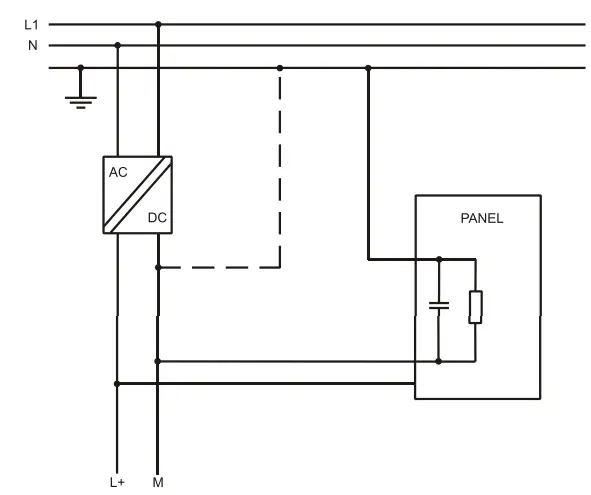
![]() Ensure that the power supply has enough power capacity for the operation of the equipment.
Ensure that the power supply has enough power capacity for the operation of the equipment.
CONNECTIONS
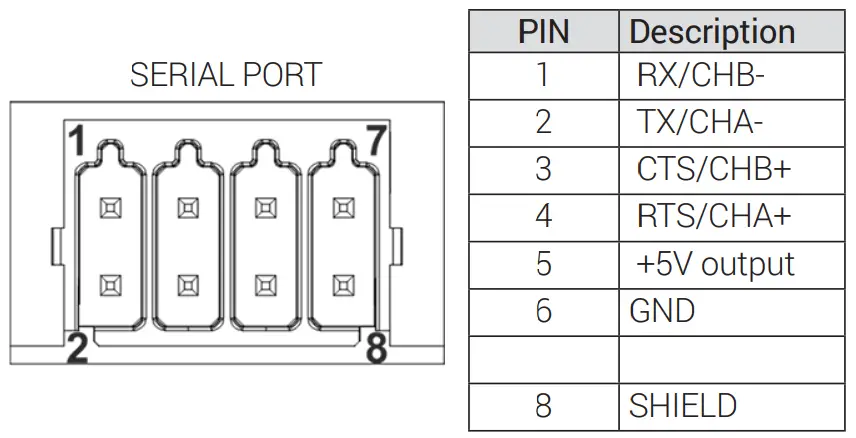
To operate in RS-485 pins 1-2 and 4-3 must be connected externally
DISPOSE OF BATTERIES
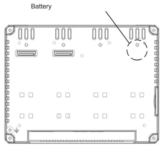
These devices are equipped with rechargeable Lithium batteries, not user-replaceable.![]() Dispose of batteries according to local regulations.
Dispose of batteries according to local regulations.![]() This device cannot be disposed of as domestic waste but according to WEEE European Directive 2012/19/EU
This device cannot be disposed of as domestic waste but according to WEEE European Directive 2012/19/EU![]()
TECHNICAL DATA
| Model | eX715MG |
| Display / Backlight | TFT Color / LED |
| Colors | 16M |
| Resolution | 1920X1080 |
| Diagonal (inches) | 15.6″ widescreen |
| Dimming | yes |
| User memory flash | 8GB |
| SD card slot | yes |
| Recipe memory | 2GB |
| Serial Port | RS-232, RS-485, RS-422 software configurable |
| Ethernet port | 2 10/100Mb, 1 10/100/1000Mb |
| USB port | 2 Host interface version 2.0 max. 500mA |
| Expansion slot | 2 Optional Plugin |
| Battery | rechargeable |
| Real-Time Clock | yes |
| Voltage | 24Vdc |
| Current rating (at 24VDC) | 1.35A |
| Weight | 5.2 Kg |
The products have been designed for use in an industrial environment in compliance with the 2014/30/EU, 2011/65/EC directives
The products have been designed in compliance with:
EN 61000-6-4
EN 61000-6-2
EN 61000-4-2
EN 61000-4-3
EN 61000-4-4
EN 61000-4-5
EN 61000-4-6
EN 61000-4-8
EN 61000-4-11
EN 61000-4-29
EN 60945
The installation of these devices into the residential, commercial, and light-industrial environments is allowed only in the case that special measures are taken in order to get conformity to IEC 61000-6-3.
Reproduction of the contents of this copyrighted document, in whole or part, without the written permission of Exor International S.p.A., is prohibited.
User Manual available on
www.exorint.com
MANEX715MGU001 V.1.00 28.02.2022
© 2022 Exor International S.p.A
Exor International S.p.A.
San Giovanni Lupatoto VR, Italy
www.exorint.com


 Installation Guide")


