ANALOG DEVICES LTC3114-1 Signal Chain Power Series Buck-Boost Converter Module Instruction Manual
DESCRIPTION
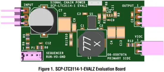
Demonstration circuit SCP-LTC3114-1-EVALZ features the LTC3114-1, a wide operating range, synchronous monolithic buck-boost converter with programmable average output current. The circuit operates with a 2.2V to 40V input voltage range.
Like all boards in the Signal Chain Power series, this board is designed to be easily plugged into other SCP boards to form a complete signal chain power system, enabling fast evaluation of low power signal chains. To evaluate this board, some universal SCP hardware is required, namely:
SCP-INPUT-EVALZ
SCP-1X2BKOUT-EVALZ
SCP-OUTPUT-EVALZ
SCP-1X5BKOUT-EVALZ
SCP-FILTER-EVALZ
SCP-5X1-EVALZ
SCP-THRUBRD-EVALZ
To properly evaluate SCP series demo boards, you will need the SCP Configurator companion software. SCP Configurator can help you choose the right board and topology for your design.
Note that this Demo Manual does not cover details important to the operation and configuration regarding the LTC3114-1. Please refer to the LTC3114-1 datasheet for a complete description of the part.
Design files for this circuit board are available. All registered trademarks and trademarks are property of their respective owners.
Table 1. Performance Summary
| SYMBOL | PARAMETER | NOTES | MIN TYP MAX | UNITS |
| VIN(MAX) | Max Input Voltage | 40 | V | |
| VOUT(MAX) | Max Output Voltage | Output capacitor rating limited. Replace for higher VOUT. | 40 | V |
| IL(LIM) | Inductor Current Limit | 1.3 1.7 2.3 | A |
BOARD IMAGE
QUICK START PROCEDURE
Demonstration circuit SCP-LTC3114-1-EVALZ is easy to set up to evaluate the performance of any SCP hardware configuration.
- The SCP-LTC3114-1-BB-EVALZ ships with a default output voltage of 5V. To change the output voltage, see “Configuration Settings” section, and modify the board accordingly. Be sure to check for open connections or solder shorts after making any modifications.
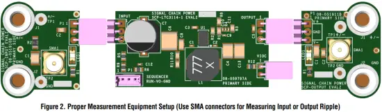
- Connect the SCP-INPUT-EVALZ and SCP-OUTPUTEVALZ boards to the SCP-LTC3114-1-BB-EVALZ (refer to Figure 2) and connect the input board to a voltage source, VSOURCE. Connect the output board to a voltmeter or dynamic load. Slowly raise the input voltage until the SCP-LTC3114-1-BB-EVALZ powers up into regulation and sweep VSOURCE through the desired range of operation.
NOTE: Make sure that the input voltage is always within specification. If using a dynamic load to measure output voltage, make sure the load is initially set to zero. - Check for proper output voltage. The output should be regulated at the programmed value (±5%).
- Once the proper output voltage is established, power off VSOURCE and similarly test other boards in the SCP system until all elements have been individually verified prior to assembling into the final circuit configuration.
NOTE: When measuring the input or output voltage ripple, use the optional SMA connector locations available on the input, output, 1 ´ 5, 1 ´ 2, and 5 ´ 1 breakout boards. Avoid using the test point connections with long scope leads.
CONFIGURATION SETTINGS
Demonstration circuit SCP-LTC3114-1-EVALZ features the LTC3114-1, a wide operating range, synchronous monolithic buck-boost converter with programmable average output current. The circuit operates with a 2.2V to 40V input voltage range.
The output of the SCP-LTC3114-1-EVALZ is resistor-programmable from 3.0V to 40V. The board can be also configured to drive VIOC capable linear regulators.
OUTPUT VOLTAGE PROGRAMMING
![]()
Table 2. Resistor Selection Guide for Common Output Voltages
| VOUT (V) | R1 (Ω) | R2 (Ω) |
| 3.0 | 2M | 1M |
| 5.0 | 2M | 499k |
| 6.0 | 2M | 402k |
| 7.0 | 2M | 332k |
| 8.0 | 2M | 287k |
| 9.0 | 2M | 249k |
| 10.0 | 2M | 221k |
| 11.0 | 2M | 200k |
| 12.0 | 2M | 182k |
| 13.0 | 2M | 165k |
| 14.0 | 2M | 154k |
| 15.0 | 2M | 143k |
| 16.0 | 2M | 133k |
| 17.0 | 2M | 124k |
| 18.0 | 2M | 118k |
| 19.0 | 2M | 110k |
| 20.0 | 2M | 105k |
| 21.0 | 2M | 100k |
| 22.0 | 2M | 95.3k |
| 23.0 | 2M | 90.9k |
| 24.0 | 2M | 86.6k |
| 25.0 (Note 1) | 2M | 82.5k |
| 30.0 (Note 1) | 2M | 69.8k |
| 35.0 (Note 1) | 2M | 59k |
| 40.0 (Note 1) | 2M | 51.1k |
Note 1. Output capacitor rating limited. Replace for higher VOUT.
RUN PIN CONFIGURATION
The RUN pin is tied to the optional SCP Run/Sequence header P1. To create a harness for this function, use Molex part 0510650300 with crimp pin 50212-8000.
To use an active run signal, use a 1.00MW for either pullup or pull-down resistors R5 and R6, short R9 with 0W, and use the drive signal from connector P1.
VOLTAGE INPUT-TO-OUTPUT CONTROL (VIOC) IMPLEMENTATION
To implement the VIOC function for this regulator, set R12 to 0W. Refer to the “Configuration Settings” section in the Demo Manual for the low-dropout (LDO) linear regulator board and use the following configuration for this board.
Table 3. VIOC Cross-Reference Designators
| VIOC SETTING REFERENCES | RBOT | RTOP | RMAX |
| VOUT Reference Designators | R2 | R1 | R8 |
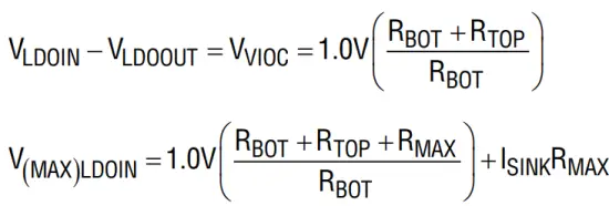
ISINK is the current through RMAX, typically 15µA, so RBOT should be sized such that the divider current runs a minimum of 100µA to minimize the ISINK error term.
PARTS LIST
| ITEM | QTY | REFERENCE | PART DESCRIPTION | MANUFACTURER/PART NUMBER |
| 1 | 1 | PCB | PRINTED CIRCUIT BOARD | ANALOG DEVICES 08_059797a |
| 2 | 2 | C1, C2 | CAP CER 68NF 16V 10% X7R 0402 | SAMSUNG CL05B683KO5NNNC |
| 3 | 1 | C10 | CAP CER C0G, FOR COMMERCIAL APP | VISHAY VJ0402A100JXAAP54 |
| 4 | 1 | C11 | CAP MONO CER CHIP FOR AUTOMOTIVE, X7R | MURATA GCM155R71E473KA55D |
| 5 | 1 | C12 | CAP MLCC 0402 (Note 2) | N/A |
| 6 | 2 | C4, C13 | CAP CER 22UF 25V 20% X7R 1812 | TDK C4532X7R1E226M250KC |
| 7 | 2 | C14, C15 | CAP MLCC 0402 (Note 2) | N/A |
| 8 | 1 | C3 | CAP CER X7R | SAMSUNG CL10B475KQ8NQNC |
| 9 | 1 | C5 | CAP CER X5R, GENERAL PURPOSE | AVX CORPORATION 06033D105KAT2A |
| 10 | 1 | C6 | CAP CER CHIP X7R | TDK C5750X7R1H106M |
| 11 | 1 | C7 | CAP ELECTROLYTIC (Note 2) | N/A |
| 12 | 1 | C8 | CAP CER X7R | AVX 12065C105KAT2A |
| 13 | 1 | C9 | CAP CER 4700PF 25V 10% X7R 0402 | SAMSUNG CL05B472KA5NNNC |
| 14 | 1 | D1 | DIODE LOW VF MEGA SCHOTTKY BARR RECT | NXP SEMICONDUCTORS PMEG2010AEH,115 |
| 15 | 1 | D2 | DIO SCHOTTKY BARRIER RECTIFIER, 2A | NEXPERIA PMEG6020ER |
| 16 | 1 | INPUT | CONN-PCB MALE HEADER 3POS 2.54MM PITCH R/A GOLD | SULLINS PBC03SBAN |
| 17 | 1 | L1 | IND SHIELDED POWER 0.0163OHM DCR, 6.01A | COILCRAFT INC. MSS1048-682NLB |
| 18 | 1 | OUTPUT | CONN FEMALE 3POS 2.54MM PITCH R/A GOLD | SULLINS PPPC031LGBN-RC |
| 19 | 1 | P1 | CONN-PCB 3POS HEADER WIRE TO BRD WAFER ASSY STRAIGHT 2MM PITCH | MOLEX 53253-0370 |
| 20 | 1 | R1 | RES SMD 2M OHM 1% 1/8W 0805 | YAGEO RC0805FR-072ML |
| 21 | 1 | R10 | RES STANDARD THICK FILM CHIP JUMPER, FOR AUTOMOTIVE | VISHAY CRCW08050000Z0EA |
| 22 | 4 | R6, R9, R11, R12 | RES THICK FILM 0805 (Note 2) | N/A |
| 23 | 1 | R2 | RES PRECISION THICK FILM CHIP | PANASONIC ERJ-6ENF4993V |
| 24 | 1 | R3 | RES PRECISION THICK FILM CHIP | PANASONIC ERJ-6ENF1002V |
| 25 | 1 | R4 | RES PRECISION THICK FILM CHIP | PANASONIC ERJ-2RKF2742X |
| 26 | 1 | R5 | RES THICK FILM CHIP, GENERAL PURPOSE | YAGEO RC0805JR-071ML |
| 27 | 1 | R7 | RES THICK FILM 0402 (Note 2) | N/A |
| 28 | 1 | R8 | RES PRECISION THICK FILM CHIP | PANASONIC ERJ-6ENF49R9V |
| 29 | 1 | U1 | IC-ADI 40V, 1A SYNCHRONOUS BUCK-BOOST DC/DC CONVERTER WITH PROGRAMMABLE OUTPUT CURRENT | ANALOG DEVICES LTC3114MPDHC-1#PBF |
| 30 | 1 | VIOC | CONN FEMALE 2POS 2.54MM PITCH R/A GOLD | SULLINS PPPC021LGBN-RC |
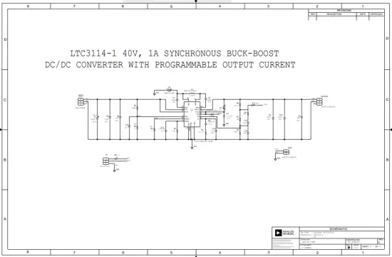
SCHEMATIC DIAGRAM
Information furnished by Analog Devices is believed to be accurate and reliable. However, no responsibility is assumed by Analog Devices for its use, nor for any infringements of patents or other rights of third parties that may result from its use. Specifications subject to change without notice. No license is granted by implication or otherwise under any patent or patent rights of Analog Devices.
ESD Caution![]() ESD (electrostatic discharge) sensitive device.
ESD (electrostatic discharge) sensitive device.
Charged devices and circuit boards can discharge without detection. Although this product features patented or proprietary protection circuitry, damage may occur on devices subjected to high energy ESD. Therefore, proper ESD precautions should be taken to avoid performance degradation or loss of functionality
Legal Terms and Conditions
By using the evaluation board discussed herein (together with any tools, components documentation or support materials, the “Evaluation Board”), you are agreeing to be bound by the terms and conditions set forth below (“Agreement”) unless you have purchased the Evaluation Board, in which case the Analog Devices Standard Terms and Conditions of Sale shall govern. Do not use the Evaluation Board until you have read and agreed to the Agreement. Your use of the Evaluation Board shall signify your acceptance of the Agreement. This Agreement is made by and between you (“Customer”) and Analog Devices, Inc. (“ADI”), with its principal place of business at One Technology Way, Norwood, MA 02062, USA. Subject to the terms and conditions of the Agreement, ADI hereby grants to Customer a free, limited, personal, temporary, non-exclusive, non-sublicensable, non-transferable license to use the Evaluation Board FOR EVALUATION PURPOSES ONLY. Customer understands and agrees that the Evaluation Board is provided for the sole and exclusive purpose referenced above, and agrees not to use the Evaluation Board for any other purpose.
Furthermore, the license granted is expressly made subject to the following additional limitations: Customer shall not
- rent, lease, display, sell, transfer, assign, sublicense, or distribute the Evaluation Board; and
- permit any Third Party to access the Evaluation Board. As used herein, the term “Third Party” includes any entity other than ADI, Customer, their employees, affiliates and in-house consultants.
The Evaluation Board is NOT sold to Customer; all rights not expressly granted herein, including ownership of the Evaluation Board, are reserved by ADI. CONFIDENTIALITY. This Agreement and the Evaluation Board shall all be considered the confidential and proprietary information of ADI. Customer may not disclose or transfer any portion of the Evaluation Board to any other party for any reason. Upon discontinuation of use of the Evaluation Board or termination of this Agreement, Customer agrees to promptly return the Evaluation Board to ADI. ADDITIONAL RESTRICTIONS. Customer may not disassemble, decompile or reverse engineer chips on the Evaluation Board. Customer shall inform ADI of any occurred damages or any modifications or alterations it makes to the Evaluation Board, including but not limited to soldering or any other activity that affects the material content of the Evaluation Board. Modifications to the Evaluation Board must comply with applicable law, including but not limited to the RoHS Directive.
TERMINATION.
ADI may terminate this Agreement at any time upon giving written notice to Customer. Customer agrees to return to ADI the Evaluation Board at that time.
LIMITATION OF LIABILITY. THE EVALUATION BOARD PROVIDED HEREUNDER IS PROVIDED “AS IS” AND ADI MAKES NO WARRANTIES OR REPRESENTATIONS OF ANY KIND WITH RESPECT TO IT. ADI SPECIFICALLY DISCLAIMS ANY REPRESENTATIONS, ENDORSEMENTS, GUARANTEES, OR WARRANTIES, EXPRESS OR IMPLIED, RELATED TO THE EVALUATION BOARD INCLUDING, BUT NOT LIMITED TO, THE IMPLIED WARRANTY OF MERCHANTABILITY, TITLE, FITNESS FOR A PARTICULAR PURPOSE OR NONINFRINGEMENT OF INTELLECTUAL PROPERTY RIGHTS. IN NO EVENT WILL ADI AND ITS LICENSORS BE LIABLE FOR ANY INCIDENTAL, SPECIAL, INDIRECT, OR CONSEQUENTIAL DAMAGES RESULTING FROM CUSTOMER’S POSSESSION OR USE OF THE EVALUATION BOARD, INCLUDING BUT NOT LIMITED TO LOST PROFITS, DELAY COSTS, LABOR COSTS OR LOSS OF GOODWILL. ADI’S TOTAL LIABILITY FROM ANY AND ALL CAUSES SHALL BE LIMITED TO THE AMOUNT OF ONE HUNDRED US DOLLARS ($100.00).
EXPORT.
Customer agrees that it will not directly or indirectly export the Evaluation Board to another country, and that it will comply with all applicable United States federal laws and regulations relating to exports.
GOVERNING LAW.
This Agreement shall be governed by and construed in accordance with the substantive laws of the Commonwealth of Massachusetts (excluding conflict of law rules). Any legal action regarding this Agreement will be heard in the state or federal courts having jurisdiction in Suffolk County, Massachusetts, and Customer hereby submits to the personal jurisdiction and venue of such courts.
The United Nations Convention on Contracts for the International Sale of Goods shall not apply to this Agreement and is expressly disclaimed.


