![]()
Manual
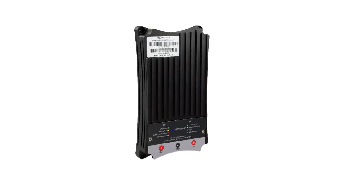
Buck-Boost DC-DC Converter
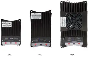
25A / 50A / 100A
Introduction
Full range programmable DC-DC converter 25/50/100A.
The solution for battery charging problems with Euro 5 and Euro 6 engines and alternator charge current protection with lithium systems.
Applications:
- Charging an extra/second battery (bank) with an eco alternator of a Euro 5 or Euro 6 engine.
- Charging lithium batteries with an alternator without temperature protection.
- Automatic activation and deactivation of the alternator charge current, based on a unique engine running detection protocol.
General features:
- Buck-Boost converter is fully programmable
- Input voltage 10..30 Vdc
- Output voltage 10..30 Vdc
- Output current (max.at 12V) 25, 50 or 100A
- Output current (max.at 24V) 12.5, 25 or 50A
- Adjustable current limiter
- Automatic activation when engine running
- Output for activation/deactivation of loads
- Battery temperature monitoring (optional)
- LED status indicators
- M8 connections
- USB for configuration/monitoring
- CAN-bus for control purposes and CAN-bus Temp Sensor communication
- Battery monitor
General description:
The Buck-Boost converter series is a program of specially developed DC-DC converters for fully-controlled charging of an extra battery or a battery bank. Application is necessary in the case of vehicles with an alternator intelligent control, and for general protection of the alternator in lithium systems.
Alternators of Euro 5 and 6 engines, which are controlled by the onboard electronics, often supply too low charging voltage even with the engine running. As a result, a Buck-Boost converter is necessary to charge the extra battery. In the case of lithium systems, the alternator must be protected against overload, resulting in overheating, which arises because the voltage control of the alternator cannot anticipate zero resistance of lithium battery systems.
To ensure that the start battery of the vehicle is always loaded with priority, the units of the Buck-Boost series will only provide power when the engine is running. This is possible thanks to the built-in engine running detection and the related programmable time-delayed switching. This also prevents the onboard voltage of the vehicle from becoming too low. It is not necessary to intervene in the system of the vehicle, install a separate motor run sensor or intervene in the CAN bus system. Apart from this detection, the Buck-Boost series equipment can also be switched on with a programmable input.
The Buck-Boost series is fully programmable through a very simple and easy PC application. The output current has an automatic limitation that is adjustable. The automatic stop becomes active as soon as the temperature comes close to a pre-set maximum.
The output voltage is fully adjustable and is independent of the input voltage due to the automatic Buck-Boost control. This control also ensures that the current will never exceed the set value. Also not when the input voltage is higher than the output voltage. The Buck-Boost range is fully programmable by means of a Windows application – TSConfig – that is very simple and intuitive to use.
TSConfig
We recommend updating your TSConfig program regularly so that you always have the latest version. Updates are available at
https://www.victronenergy.com/support-and-downloads/software
Warnings
Read this manual carefully before installing and commissioning the equipment. Store the manual carefully and pass it on to a new user of this product!
Explanation of the symbols used
 | DANGER! Safety instruction: Failure to comply will result in death or serious injury. |
 | WARNING! Safety instruction: Failure to comply may result in death or serious injury. |
| CAUTION! Failure to do so may result in property damage and limit the functionality of the product. | |
 | INSTRUCTION Additional information for operating the product. |
General safety instructions
The manufacturer cannot be held liable for damage in the following cases:
- mounting or connection errors
- product damaged by mechanical impacts and overvoltage
- modifications of the product without the express permission of the manufacturer
- use with purposes other than those described in the manual
For safety reasons when installing and using electrical appliances, always observe the risks of electric shock, fire risk, and injury!
General safety
| DANGER! Use a fire extinguisher suitable for electrical appliances in the event of a fire. Always have a fire extinguisher at hand in the premises and use it appropriately. |
| WARNING!
|
CAUTION!
|
Safety when assembling the product
| DANGER! Do not mount the product in places where there is a risk of a gas or dust explosion. |
| WARNING! Provide a stable mounting! The product must be securely mounted and attached to prevent it from falling, dropping, and preventing contact of the connections with surrounding objects. |
CAUTION!
|
Safety at the electrical connection of the product
| DANGER! Risk of fatal electric shock!
|
| WARNING!
|
CAUTION!
|
Safe use of the product
| WARNING! If the product is used in environments with lead-acid batteries, the room should be well ventilated. Explosive hydrogen gas is released from these batteries, which can be ignited by electric sparks. CAUTION!
|
CAUTION!
|
Safety when handling batteries
| WARNING! Batteries may contain harsh and corrosive acids. Avoid any and all physical contact with the battery fluid. In case of skin contact with battery fluids, wash the affected areas of the skin with water. In case of injuries due to acids, please be sure to consult a physician.CAUTION!
Risk of explosion!
|
CAUTION!
|
Connection

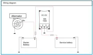
Simplified diagram:
![]()
Connections:
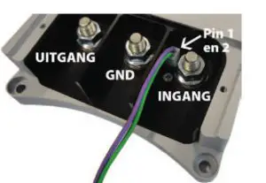
IN: Converter input (alternator/starter battery)
GND: GND (chassis)
OUT: Converter output (extra battery)
Pin 1: Input/output (purple wire)
Pin 2 : Input/output (green wire)
When Pin 1 or Pin 2 is being used, use the resistors supplied to ensure safety. This is no longer necessary in the most recent models (recognizable by their ridged housing).
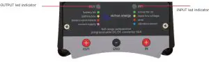
LED indicators
The Buck-Boost DC-DC converter is equipped with two RGB LEDs.
The IN LED has the following functions:
Green: The converter is switched on (by the engine running detection, or by applying a voltage on pin 1).
Yellow: The input voltage is lower than the set threshold to allow the converter to switch on.
Red: The internal temperature is higher than the set safety threshold. The converter is switched on
Blue: Short light pulses = the engine running detection is active, the converter turns on after a delay.
Flashes slowly = the converter is switched off and blocked for switching on due to A too low input voltage.
The OUT LED has the following functions:
Green: The converter is switched off. The connected battery has a correct terminal voltage.
Yellow: The converter is switched off. The connected battery has too low a terminal voltage.
Red: The converter is switched off. The connected battery is empty or the battery is not connected.
Purple: The converter is switched on and supplies power to the connected battery and/or electrical consuming points.
Flashing purple: The converter is switched off. When the converter starts up, the set voltage of the second battery is too low (safety circuit 31 is active). The normal alerts of each LED blinks slowly for power saving (Setting 27).
Engine running detection
The converter has a unique engine running detection in order to be able to detect a running vehicle engine. This prevents the converter from charging the starter battery if the alternator does not supply power. The converter is switched on: When the engine is running and the supply voltage is >= (adjustable) volts and any (adjustable) minute blocking is over.
Pin 1 input (as an alternative to the engine running detection)
The converter may also be switched on with a switch or relay contact.
Switch on:
The converter is switched on:
If pin 1 input >= 2 volts, and the supply voltage is >= (adjustable) volts and any blocking is over.
Important when installing!
Basic settings
At the time of commissioning, the following basic settings shall be applied:
| Setting | 12V – 12V 24V – 24V 12V – 24V |
| 20 Output voltage | 14.4V 28.8V 28.8V |
| 22 Maximum output current | 60% of the current supplied by the vehicle’s alternator (max.) |
| 24 Undervoltage threshold | 11.8V – 12.2V 23.8V – 24.2V 11.8V – 12.2V |
On-board voltage
The on-board voltage under setting 24 of the TSConfig software shall not be set too low. This value may be adjusted by a qualified electrician only!
Input and output fuse
Use the following input and output fuse and cable intersection depending on the Buck-Boost type:
12 VOLTS INPUT
| Buck-Boost type | Fuse value / Ampères | Cable thickness (< 5 meters) |
| 25A | 40 Ampère (A) | 16 mm 2 |
| 50A *) | 60 Ampère (A) | 35 mm 2 |
| 100A *) | 125 Ampère (A) | 50 mm 2 |
24 VOLTS INPUT
| Buck-Boost type | Fuse value / Ampères | Cable thickness (< 5 meters) |
| 25A | 30 Ampères (A) | 16 mm 2 |
| 50A *) | 40 Ampères (A) | 35 mm 2 |
| 100A *) | 80 Ampères (A) | 50 mm 2 |
*) CAUTION. In order to use the 50A or 100A, the alternator must have sufficient charging capacity to be able to supply the maximum input voltage that the converter requires. For details, please see the input voltage (max.) in the table.
Connection
First connect all GND cables to the converter, the battery, and the chassis, and then only the positive (+) cable. This is important because in the converter everything refers to GND.
When the two-plus (+) cables are connected without GND, the potential difference between the plus (+) connecensures uncontrolled and unsecured currents! Always check that the GND connection on the middle M8 connection is correctly connected. The converter has no reverse polarity protection!
Converter operation
The Buck-Boost DC-DC converter operates on the principle of buck-boost. This means that the input voltage may be both higher and lower than the set output voltage. The amount of the charge current remains in both situations always fully under control. A brief overview of possible conversions:
| Buck-Boost type | 12V – 12V Default | 24V – 24V Default | 12V – 24V Default |
| 25A charging current max. | 25A | 15A | 10A |
| 50A charging current max. | 50A | 25A | 20A |
| 100A charging current max | 100A | 50A | 50A |
Charging current limiter
The output current is determined by the following factors:
Setting: The maximum desired charging current is set via the USB connection (with the Windows application TSConfig).
Temperature: If the converter temperature comes close to the set maximum temperature, the charging current is automatically limited. As a result, the temperature of the Buck-Boost inverter is never inadmissibly high.
TSConfig application
The Buck-Boost converters can be configured extensively with TSConfig software. This software also includes a monitor window, where the real-time operation of the converter can be tracked. The following image shows a screenshot of the TSConfig software:
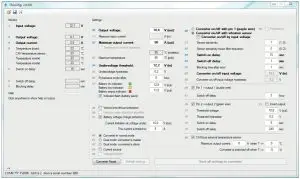
The TSConfig software and manual can be downloaded from: https://www.victronenergy.com/support-anddownloads/software
Technical specifications
| Buck-Boost DC-DC Converter | 25A | 50A | 100A |
| Input voltage range | 10 to 30 Volt | ||
| Threshold Undervoltage | 10V | ||
| Output voltage range | 10-30V | ||
| Maximum charging current | 12V : 25A 24V : 15A | 12V : 50A 24V : 25A | 12V: 100A 24V: 50A |
Power consumption
| Converter switched off, LEDs | 7mA |
| from energy-saving mode) |
Input voltage on/off (pin 1, purple wire)
| Threshold voltage ‘On’ | > 2V |
| Maximum input voltage | 30V |
Output pin 1 and pin 2
| Output voltage as enabled | Spinout = Vin |
| Maximum voltage (per pin) | Spinout = 1.5A |
GENERAL
| Operating temperature range | -25…+60°C | ||
| Ambient temperature | Max power at 40°C | ||
| Weight | 0.6 kg | 1.4 kg | 4.1 kg |
| Dimensions | 165 x 120 x 30 mm | 213 x 120 x 30 mm | 288 x 162 x 95 mm |
Distributor:……….
Serial number:……….
Version: 09
Date: September 10 th , 2021
![]()
Victron Energy B.V.
De Paal 35 | 1351 JG Almere
PO Box 50016 | 1305 AA Almere | The Netherlands
General phone : +31 (0)36 535 97 00
E-mail : [email protected]
www.victronenergy.com


