![]() Smart BatteryProtect 48/100
Smart BatteryProtect 48/100
Instruction Manual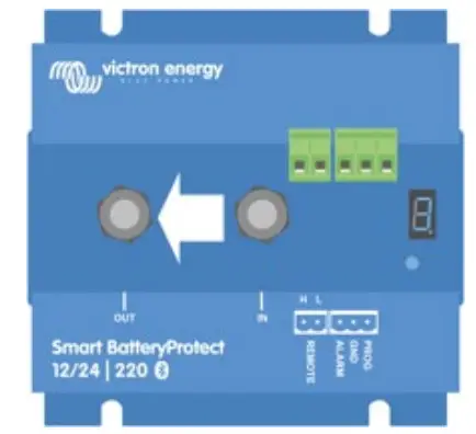
Installation
- The Smart BatteryProtect (SBP) must be installed in a well-ventilated area and preferably close (max 50 cm) to the battery (but, due to possible corrosive gasses not above the battery!). The voltage drop over a long or undersized cable between the battery plus and the SBP may result in a short circuit alarm when starting up the load, or an unexpected shutdown.
- A properly sized fuse must be inserted according to local regulations in the cable between the battery and the SBP.
- The SBP is designed to allow current to flow from IN (battery) to OUT (load) terminals only.
Reverse currents from OUT to IN terminals are strictly forbidden and will damage the device. If you wish to use the SBP as a disconnection for a charge source, you must orient the unit in the system so that the current is flowing in the intended direction, IN to OUT. - The short circuit protection of the SBP will be activated if you try to directly connect loads with capacitors on their input (eg inverters). For that use case, please use the SBP to control the remote on/off switch on the inverter, instead of disconnecting the higher power DC line.
- Use a 1,5mm² wire (included) for the minus connection, which should be connected directly to the battery minus (or the chassis of a vehicle). No other equipment should be connected to this wire.
- The SBP automatically detects the system voltage after the connection of plus and minus to the battery. During the voltage detection, the 7-segment display shows a series of flashes between the top and lower parts.
- Do not connect the load output until the SBP has been fully programmed.
- A remote on-off switch can be connected between Remote H and Remote L (see figure 1).
Alternatively, terminal H can be switched to battery plus, or terminal L can be switched to battery minus. - A buzzer, LED or relay can be connected between the alarm output and the battery plus (see figure 1).
Maximum load on the alarm output: 50 mA (short circuit proof).
Load disconnect events and alarm output options
Buzzer or LED mode (buzzer or LED connected to the alarm output):
- In case of under voltage, a continuous alarm will start after 12 seconds. The SBP will disconnect the load after 90 seconds and the alarm will stop. Reconnect delay: 30 seconds.
- In case of overvoltage, the load will be disconnected immediately and an intermittent alarm will remain on until the overvoltage problem has been corrected. There is no reconnect delay.
Relay mode (relay connected to the alarm output): - In case of under voltage, the relay will engage after 12 seconds. The SBP will disconnect the load after 90 seconds and the relay will disengage.
- In case of over voltage, the load will be disconnected immediately and the alarm output will remain inactive. Overvoltage trip level: 65.2V Li-ion mode:
- Connect the load disconnect output of the VE. Bus BMS to Remote H terminal.
The load is disconnected immediately when the load-disconnect output of the VE. Bus BMS switches from ‘high’ to ‘free floating’ (due to battery cell under voltage, over-voltage, or over temperature). The under voltage thresholds and alarm output of the SBP are inactive in this mode.
Operation
There are 6 possible error modes, indicated by the 7-segment display and on a Bluetooth-enabled device:
- E1 Short circuit detected
- E2 Overload or over temperature / P2 over temperature warning
- E3 Under voltage / P3 under voltage warning
- Overvoltage
- Settings Failure
- Reference Voltage Failure
- BMS Lockout
Programming
When switched off (remote open), the SBP can be programmed by connecting the PROG pin to the ground.
Alternatively, it can be programmed with a Bluetooth-enabled smartphone or tablet regardless of the remote status.
The 7-segment display will first step through the shutdown and restart voltages. Disconnect the PROG pin when the desired voltage is displayed.
The display will confirm the chosen voltage and default mode (R) twice.
Reconnect the PROG pin to the ground if another mode is (b or c) is required. Disconnect when the required mode is displayed.
The display will confirm the chosen voltage and mode twice.
Bluetooth can be disabled/re-enabled with the VictronConnect app or by connecting the PROG pin to the ground and selecting F(enable) or h (disable). See table below
Programming table
| 7 segment display | Under voltage shut down 48V system | Under voltage restart 48V system |
| 0 | 42V | 48V |
| I | 40V | 46V |
| 2 | 38V | 46V |
| 3 | 45V | 53V |
| 4 | 46V | 55,2V |
| S | 42V | 51,2V |
| 6 | 46V | 51,2V |
| 1 | 47,2V | 51,2V |
| 6 | 48V | 52V |
| 9 | 40V | 52,8V |
| User-defined settings with Bluetooth | ||
| Fl | Buzzer or LED mode | |
| b | Relay mode | |
| C | Li-ion mode | |
| F | Bluetooth Enable | |
| h | Bluetooth Disable | |
| Smart BatteryProtect | SBP 48|100 |
| Maximum cont. load current | 100A |
| Peak current | 250A |
| Operating voltage range | 24 – 70V |
| Current consumption | When on: 1,9mA When off or low voltage shutdown: 1,7mA |
| Alarm output delay | When on: 1,7mA When off or low voltage shutdown: 1,6mA |
| Max. load on alarm output | 12 seconds |
| Load disconnect delay | 50mA (short circuit proof) |
| Default thresholds | 90 seconds (immediate if triggered by the VE.Bus BMS) |
| Operating temperature range | Disengage: 42V Engage: 48V |
| Connection | Full load: -40°C to +40°C (up to 60% of nominal load at 50°C) |
| Weight | M8 |
| Dimensions (hxwxd) | 0,8kg 1.8 lbs |
Example Wiring Diagrams
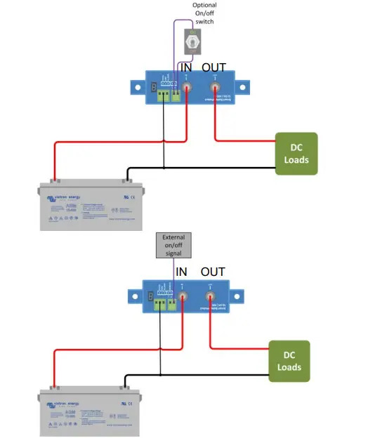 | 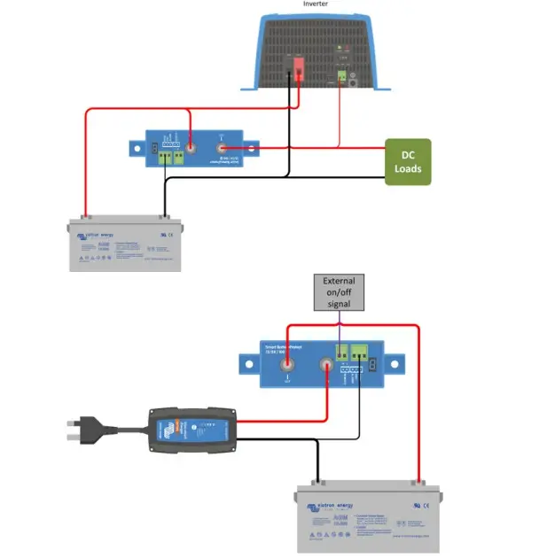 |
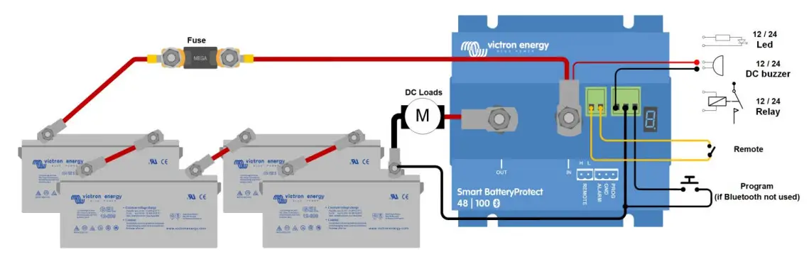
Figure 1 Connection diagram of the SBP 48|100 (use the remote input for system on/off functionality)
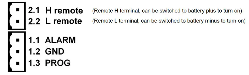
Figure 2: Connection diagrams and pin numbering
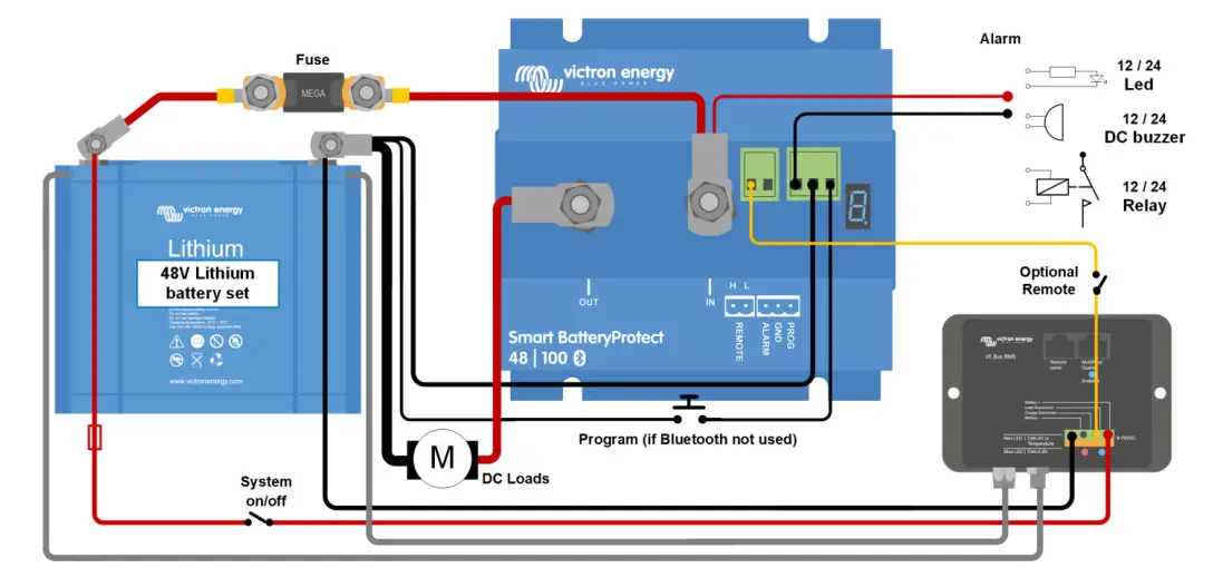
Figure 3: System with 48V Li-ion battery set
(Applicable with VE.Bus BMS or mini BMS)
Note: When in Li-ion mode, the SBP will disengage when the H input becomes free-floating, and will remain disengaged for 30 seconds even if it receives a re-engage signal within that time period. After 30 seconds it will respond immediately to a re-engage signal. Therefore, there will normally be no waiting time if the SBP is used as a system on-off switch (use the System on/off switch in the positive supply of the BMS for this purpose).
Similarly, if a system shutdown occurred due to low cell voltage, the SBP will remain disengaged for 30 seconds even if it receives a re-engage signal within that time period (which will happen when no other loads are connected to the battery). After 3 attempts to re-engage, the SBP will remain disengaged until battery voltage has increased to more than 52V during at least 30 seconds (which is a sign that the battery is being recharged). The under voltage thresholds and alarm output of the SBP are inactive in this mode. To manually make it start again, briefly disconnect and reconnect the remote on/off terminal or switch the BMS off and on again.
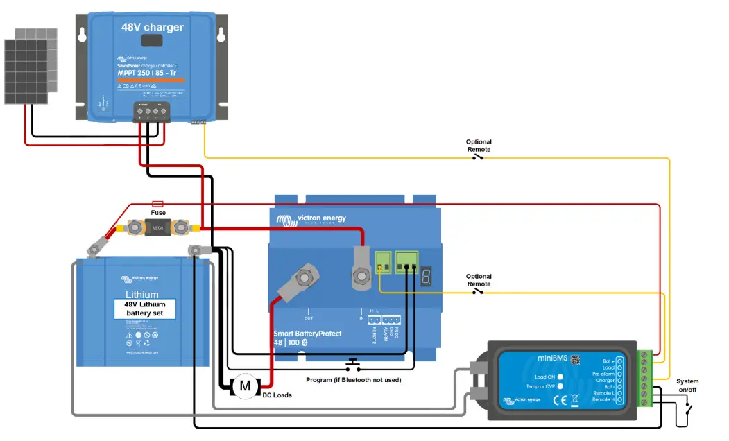 Figure 4: DC solar system with Lithium battery (applicable with VE.Bus BMS or miniBMS)
Caution: uncontrolled reverse current will flow through a Smart BatteryProtect if Vout > Vin. Therefore, never use a Smart BatteryProtect for battery-to-battery charging.
Victron Energy B.V. / De Paal 35 / 1351 JG ALMERE / Nederland
Telefoon: (+31) (0)36 535 97 00 / www.victronenergy.com / e-mail: [email protected]


