![]() AMVT***P1400**
AMVT***P1400**
AIR HANDLERS INSTALLATION &
OPERATING INSTRUCTIONS
AMVT***P1400 Air Handlers
This device, which was assembled by Daikin Comfort Technologies
Manufacturing, L.P., contains a component that is classified as an intentional radiator. This intentional radiator has been certified by the FCC: FCC ID QOQBGM111. And this international radiator has an Industry Canada ID: IC 5123A-BGM111.
This device complies with Part 15 of the FCC’s Rules. Operation of this device is subject to two conditions:
- This device may not cause harmful interference; and
- This device must accept any interference received, including interference that may cause undesirable operation.
And this device meets the applicable Industry Canada technical specifications.
The manufacturer of the intentional radiator (model no. BGM111) is Silicon Laboratories Finland Oy, which can be contacted by calling 617-951-0200. (www.silabs.com)
The FCC responsible party is Daikin Comfort Technologies Manufacturing, L.P. may be contacted by calling 713-861-2500, or at 19001 Kermier Rd., Waller TX 77484. (www.goodmanmfg.com)
This equipment complies with FCC radiation exposure limits. To ensure compliance, human proximity to the antenna shall not be less than 20 cm during normal operations.
NOTE: Changes or modifications not expressly approved by the party responsible for compliance could void the user’s authority to operate the equipment.![]() WARNING
WARNING
Only personnel that have been trained to install, adjust, service, maintenance or repair (hereinafter, “service”) the equipment specified this manual should service the equipment.
This equipment is not intended for use by persons (including children) with reduced physical, sensory or mental capacities, or lack of experience and knowledge, unless they have been given supervision or instruction concerning use of the appliance by a person responsible for their safety.
Children should be supervised to ensure that they do not play with the equipment.
The manufacturer will not be responsible for any injury or property damage arising from improper supervision, service or service procedures. If you service this unit, you assume responsibility for any injury or property damage which may result. In addition, in jurisdictions that require one or more licenses to service the equipment specified in this manual, only licensed personnel should service the equipment. Improper supervision, installation, adjustment, servicing, maintenance or repair of the equipment specified in this manual, or attempting to install, adjust, service or repair the equipment specified in this manual without proper supervision or training may result in product damage, property damage, personal injury or death.![]() WARNING
WARNING
Do not bypass safety devices.
![]() is a registered trademark of Maytag Corporation or its related companies and is used under license. All rights reserved.
is a registered trademark of Maytag Corporation or its related companies and is used under license. All rights reserved.
RECOGNIZE SYMBOL THIS
AS A SAFETY PRECAUTION
NOTE: SPECIFICATIONS AND PERFORMANCE DATA LISTED HEREIN ARE SUBJECT TO CHANGE WITHOUT NOTICE.![]() WARNING
WARNING![]() HIGH VOLTAGE
HIGH VOLTAGE
Disconnect all power before servicing or installing this unit. Multiple power sources may be present. Failure to do so may cause property damage, personal injury or death.![]() WARNING
WARNING
To prevent the risk of property damage, personal injury, or death, do not store combustible materials or use gasoline or other flammable liquids or vapors in the vicinity of this unit.![]() WARNING
WARNING
This product is factory-shipped for use with 208/240/1/60 electrical power supply. DO NOT reconfigure this air handler to operate with any other power supply.![]() CAUTION
CAUTION
When installing or servicing this equipment, safety clothing, including hand and eye protection, is strongly recommended. If installing in an area that has special safety requirements (hard hats, etc.), Observe these requirements.![]() WARNING
WARNING
To avoid property damage, personal injury or death due to electrical shock, this unit MUST have AN UNINTERRUPTED, UNBROKEN electrical ground. The electrical ground circuit may consist of an appropriately sized electrical wire connecting the ground lug in the unit control box to the building electrical service panel. Other methods of grounding are permitted if performed in accordance with the National Electric Code (NEC) / American National Standards Institute (ANSI) / National Fire Protection Association (NFPA) 70 and local/state codes. In Canada, electrical grounding is to be in accordance with the Canadian Electric Code (CSA) C22.1.![]() DANGER
DANGER
PELIGRO CARBON MONOXIDE POISONING HAZARD
Special Warning for Installation of Furnace or Air Handling Units in Enclosed Areas such as Garages, Utility Rooms or Parking Areas
Carbon monoxide producing devices (such as an automobile, space heater, gas water heater, etc.) should not be operated in enclosed areas such as unventilated garages, utility rooms or parking areas because of the danger of carbon monoxide (CO) poisoning resulting from the exhaust emissions. If a furnace or air handler is installed in an enclosed area such as a garage, utility room or parking area and a carbon monoxide producing device is operated therein, there must be adequate, direct outside ventilation.
This ventilation is necessary to avoid the danger of CO poisoning which can occur if a carbon monoxide producing device continues to operate in the enclosed area. Carbon monoxide emissions can be (re)circulated throughout the structure if the furnace or air handler is operating in any mode.
CO can cause serious illness including permanent brain damage or death.
B10259-216
Important Safety Instructions
The following symbols and labels are used throughout this manual to indicate immediate or potential safety hazards. It is the owner’s and installer’s responsibility to read and comply with all safety information and instructions accompanying these symbols. Failure to heed safety information increases the risk of personal injury, property damage, and/or product damage.
Shipping Inspection
Always transport the unit upright; laying the unit on its side or top during transit may cause equipment damage. The installer should inspect the product upon receipt for shipping damage and subsequent investigation is the responsibility of the carrier. The installer must verify the model number, specifications, electrical characteristics, and accessories are correct prior to installation. The distributor or manufacturer will not accept claims from dealers for transportation damage or installation of incorrectly shipped units.
2.1 Parts
Inspect the unit to verify all required components are present and intact. Report any missing components immediately to the manufacturer or to the distributor. Use only factory authorized replacement parts (see Section 5).
Make sure to include the full product model number and serial number when reporting and/or obtaining service parts.
2.2 Handling
Use caution when transporting / carrying the unit. Do not move unit using shipping straps. Do not carry unit with hooks or sharp objects. The preferred method of carrying
the unit after arrival at the job site is to carry via a towhee hand truck from the back or sides or via hand by carrying at the cabinet corners.
2.3 Shipping Material Removal
IMPORTANT: All Shipping Material used to protect the equipment, and the equipment’s components, during transit should be removed before final installation.
Codes & Regulations
This product is designed and manufactured to comply with applicable national codes. Installation in accordance with such codes and / or prevailing local codes / regulationsis the responsibility of the installer. The manufacturer assumes no responsibility for equipment installed in violation of any codes or regulations.
The United States Environmental Protection Agency (EPA) has issued various regulations regarding the introduction and disposal of refrigerants. Failure to follow these regulations may harm the environment and can lead to the imposition of substantial fines. Should you have any questions please contact the local office of the EPA and / or refer to EPA’s website www.epa.gov.
Replacement Parts
When reporting shortages or damages, or ordering repair parts, give the complete product model and serial numbers as stamped on the product. Replacement parts for thisproduct are available through your contractor or local distributor. For the location of your nearest distributor consult the white business pages, the yellow page section of the local telephone book or contact:
HOMEOWNER SUPPORT
DAIKIN COMFORT TECHNOLOGIES
MANUFACTURING, L.P.
19001 KERMIER ROAD
WALLER, TEXAS 77484
(855) 770-5678
Pre-Installation Considerations
5.1 Preparation
Keep this document with the unit. Carefully read all instructions for the installation prior to installing product.
Make sure each step or procedure is understood and any special considerations are taken into account before starting installation. Assemble all tools, hardware and supplies needed to complete the installation. Some items may need to be purchased locally. Make sure everything needed to install the product is on hand before starting.
5.2 System Matches
The entire system (combination of indoor and outdoor sections) must be manufacturer approved and Air Conditioning, Heating, and Refrigeration Institute (AHRI) listed.
NOTE: Installation of unmatched systems is not permitted.
5.3 Interconnecting Tubing
Give special consideration to minimize the length of refrigerant tubing when installing air handlers. Refer to Remote Cooling / Heat Pump Service Manual RS6200006,and TP-107 Long Line Set Application R-410A for tubing guidelines. If possible, allow adequate length of tubing such that the coil may be removed (for inspection or cleaning services) from the cabinet without disconnecting the tubing.
5.4 Clearances
The unit clearance from a combustible surface may be 0”. However, service clearance must take precedence. A minimum of 24” in front of the unit for service clearance is required. Additional clearance on one side or top will be required for electrical wiring connections. Consult all appropriate regulatory codes prior to determining final clearances. When installing this unit in an area that may become wet (such as crawl spaces), elevate the unit with a sturdy, non-porous material. In installations that may lead to physical damage (i.e. a garage) it is advised to install a protective barrier to prevent such damage. Always install units such that a positive slope in condensate line (1/4” per foot) is allowed.
5.5 Horizontal Applications
If installed above a finished living space, a secondary drain pan (as required by many building codes), must be installed under the entire unit and its condensate drain line
must be routed to a location such that the user will see the condensate discharge.
Installation Location
NOTE: These air handlers are designed for indoor installation only at a max altitude of 10,500 feet above sea level or a min altitude of -184 feet below sea level.
If the unit is located in an unconditioned area with high ambient temperature and/or high humidity, the air handler may be subject to nuisance sweating of the casing. On these installations, a wrap of 2” fiberglass insulation with a vapor barrier is recommended. A secondary drain pan below the unit is also recommended to protect the installation site.
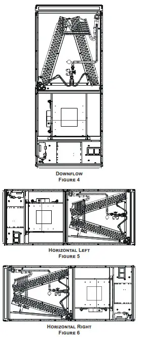
This product line may be installed in one of the upflow, downflow, horizontal left or horizontal right orientations as shown in Figures 3, 4, 5 and 6. The unit may be installed in horizontal left orientation as shipped (refer to specific sections for more information).
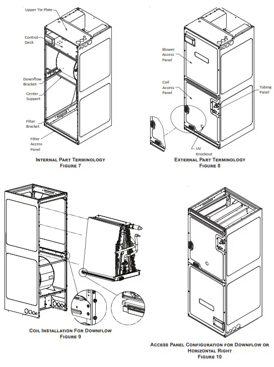
6.1 Upflow and Downflow Installation (Figure 3 & 4)
- Remove blower access panel and coil access panel. The coil access panel and tubing panel may remain screwed together during this procedure. Remove and retain the seven (7) screws securing the coil access panel to the cabinet and the six (6) screws securing the blower access panel to the cabinet.
- Slide the coil assembly out from the cabinet. Use the drain pan to pull the assembly from the cabinet.
IMPORTANT: Do not use manifolds, copper lines, or the flowrate to pull the coil assembly out. Failure to do so may result in braze joint damage and leaks. - Removal of the center support is required on units with 21” wide cabinet. Remove and retain the two (2) screws that secure the center support to the cabinet. Remove the center support.
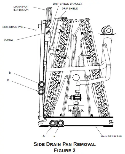
- The horizontal drip shield, side drain pan, and drain pan extension must be removed. Follow the “Side Drain Pan and Extension Removal Instructions”.
- For Upflow Installation:
a. Using the drain pan to hold the coil assembly, slide the coil assembly back into the cabinet.
b. Reinstall the center support (if removed) using the two (2) screws removed in Step 3.
c. Reinstall the coil access panels and reinstall
blower access panel removed in Step 1 as shown in Figure 9. - For Downflow Installation:
a. Position the unit in the downflow position.
b. Using the drain pan to hold the coil assembly, slide the coil assembly back into the cabinet on the downflow brackets as shown in Figure 9.
c. Reinstall the center support (if removed) using the two (2) screws removed in Step 3.
d. Reinstall the coil access panels and reinstall blower access panel removed in Step 1 as shown in Figure 10.
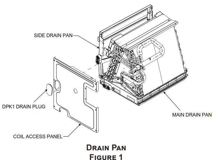
Side Drain Pan and Extension Removal Instructions
Refer to Figure 2, remove the two (2) screws that secure the drip shield support brackets to the condensate collectors (front and back). Unsnap the side drain pan from the bottom drain pan using a screwdriver or any small lever. The side drain pan, drip shield brackets and the drain pan extension may now be removed. From Figure 2, drain port labeled (A) is the primary drain for this application and condensate drain line must be attached to this drain port. Drain port (a) is for the secondary drain line (if used). When the side drain pan is removed, the drain port opening in the access panel must be covered by the accessory drain port plug (DPK1) as shown in Figure 1.
| Drain Port Plug | ||
| Kit Number | Description | Application |
| DPK1 | Side Drain Port Plug | All Models |
Drain Port Plug Kit
Table 1
 |  |
6.2 Horizontal Left Installation (Figure 5)
No field modifications are permissible for this application. Install unit as shown in Figure 5.
Drain port labeled (B) in Figure 2 is the primary drain for this application and condensate drain line must be attached to this drain port. Drain port (b) is for the secondary drain line (if used).
Remove red plugs from side drain pan before connecting condensate drain pipes. Use removed plug to close drain ports on vertical drain pan.
6.3 Horizontal Right Installation (Figure 6)
NOTE: For AMVT24BP1400** only: If installing a filter, an external filter must be used when installing the unit in Horizontal Right. A filter will not fit on the internal filter rails in these applications.
- Before inverting the air handler, remove blower access panel and coil access panel. The coil access panel and tubing panel may remain screwed together during this procedure. Remove and retain the seven (7) screws securing the coil access panel to the cabinet and the six (6) screws securing the blower access panel to the cabinet.
- Slide the coil assembly out from the cabinet. Use the drain pan to pull the assembly from the cabinet.
NOTE: Do not use manifolds, copper lines, or the flowrator to pull the coil assembly out. Failure to do so may result in braze joint damage and leaks. - Removal of the center support is required on units with 21” wide cabinet. Remove and retain the two (2) screws that secure the center support to the cabinet. Remove the center support.
- Position the unit in the downflow position.
- Remove side drain pan extension if present.
- Using the drain pan to hold the coil assembly, slide the coil assembly back into the cabinet on the downflow brackets as shown in Figure 8.
- Reinstall the center support (if removed) using the two (2) screws removed in Step 5.
- Reinstall the coil access panels and reinstall blower access panel removed in Step 1 as shown in Figure 10.
- Drain Connections for Horizontal Right Installation
a. Drain port labeled (B) in Figure 2 is the primary drain for this application and condensate drain line must be attached to this drain port. Drain port (b) is for the secondary drain line (if used).
b. Remove red plugs from side drain pan before connecting condensate drain pipes. Use removed plug to close drain ports on vertical drain pan.
NOTE: If removing only the coil access panel from the unit, the filter access panel must be removed first. Failure to do so will result in panel damage.
6.4 Humid Environment Installations
NOTE: Each service kit mentioned in this instruction is available through your local distributor. The kits are not supplied with the air handler and must be used to assist with condensation management in humid environment applications. The individual installation instructions provided with each kit must be followed.
6.4.1 ALL INSTALLATIONS – HUMID ENVIRONMENTS
Installations in areas where the return air environment sees humidity levels above 65% relative humidity, a High Humidity Kit (HHK) must be used. See Table 2 for Model and Kit assignment.
| HHK0004 | HHK0005 | HHK0006 | HHK0007 | HHK0008 |
| AMVT24B AMVT30B AMVT36B | AMVT36C AMVT42C AMVT48C | AMVT48C | AMVT48D | AMVT48B |
Table 2
6.4.1.2 Downflow Installations – Humid Environments
To prevent the coil pan “sweating”, the mandatory Downflow Kit (DFK) must also be used in addition to the High Humidity Kit (HHK). See Table 3 for the correct DFKfor each model.
| DFKE-02 | DFKE-03 |
| AMVT24B | AMVT48C |
| AMVT30B | AMVT48D |
| AMVT36B | AMVT60D |
| AMVT36C | AMVT42C |
Table 3
6.4.1.3 Horizontal Installations – Humid Environments
In addition to the High Humidity Kit (HHK), in applications where the air handler is installed in the horizontal position (Left or Right), and the return air environment seeshumidity levels above 65% relative humidity, a Condensate Management Kit (CMK) must be used for field application. Applicable Kit and Model listing can be found in Table 4.
| CMK0018 | CMK0019 | CMK0020 |
| AMVT24B AMVT36C | AMVT30B AMVT36B AMVT42C | AMVT48C AMVT48D AMVT60D |
Table 4
Refrigerant Lines
![]() WARNING
WARNING
THIS PRODUCT IS FACTORY-SHIPPED WITH R410A AND DRY NITROGEN MIXTURE GAS UNDER PRESSURE. USE APPROPRIATE SERVICE
TOOLS AND FOLLOW THESE INSTRUCTIONS TO PREVENT INJURY.
NOTE: Refrigerant tubing must be routed to allow adequate access for servicing and maintenance of the unit. Do not install the air handler in a location that violates the instructions provided with the condenser. If the unit is located in an unconditioned area with high ambient temperature and/or high humidity, the air handler may be subject to nuisance sweating of the air handler cabinet. On these installations, a wrap of 2” fiberglass insulation with a vapor barrier is recommended.
7.1 Tubing Size
For the correct tubing size, follow the specification for the condenser/heat pump.
7.2 Tubing Preparation
All cut ends are to be round, burr free, and clean. Failure to follow this practice increases the chances for refrigerant leaks. The suction line is spun closed and requires tubing cutters to remove the closed end.
NOTE: To prevent possible damage to the tubing joints, do not handle coil assembly with manifold or flowrator tubes. Always use clean gloves when handling coil assemblies.
NOTE: The use of a heat shield is strongly recommended when brazing to avoid burning the serial plate or the finish of the unit. Heat trap or wet rags must be used to protect heat sensitive components such as service valves and TXV valves sensing bulb.![]() WARNING
WARNING
A QUENCHING CLOTH IS STRONGLY RECOMMENDED TO PREVENT SCORCHING OR MARRING OF THE EQUIPMENT FINISH WHEN BRAZING CLOSE TO THE PAINTED SURFACES. USE BRAZING ALLOY OF 5% MINIMUM SILVER CONTENT.![]() CAUTION
CAUTION
APPLYING TOO MUCH HEAT TO ANY TUBE CAN MELT THE TUBE. TORCH HEAT REQUIRED TO BRAZE TUBES OF VARIOUS SIZES MUST BE PROPORTIONAL TO THE SIZE OF THE TUBE. SERVICE PERSONNEL MUST USE THE APPROPRIATE HEAT LEVEL FOR THE SIZE OF THE TUBEBEING BRAZED.
7.3 Tubing Connections
An adjustable TXV with bulb is installed on the vapor tube from the factory.
- Remove refrigerant tubing panel or coil (lower) access panel.
- Remove access valve fitting cap and depress the valve stem in access fitting to release pressure. No pressure indicates possible leak.
- Replace the panel.
- Remove the spin closure on both the liquid and suction tubes using a tubing cutter.
- Insert liquid line set into liquid tube expansion and slide grommet about 18” away from braze joint.
- Insert suction line set into suction tube expansion and slide insulation and grommet about 18” away from braze joint.
- Braze joints. Quench all brazed joints with water or a wet rag upon completion of brazing.
IMPORTANT NOTE: Ensure coil slides on the rails along the groove provided on the drain pan side walls. Failure to do so will result in improper condensate drainage.
7.4 Thermal Expansion Valve System Adjustment The following information for the indoor unit should be verified before attempting to charge system or adjust TXV if
necessary.
- Total static pressure is .5” WC or less.
- Airflow is correct for installed unit.
- Airflow tables are in the installation manual and Spec Sheet for Indoor Unit.
- Complete airflow tables and charging information are in Service Manual RS6200006.
- The outdoor temperature must be 60°F or higher.
- Set the room thermostat to COOL, fan switch to AUTO.
- Set the temperature control well below room temperature.
Superheat adjustments should not be made until indoor ambient conditions have stabilized. This could take up to 24 hours depending on indoor temperature and humidity. Before checking superheat run the unit in cooling for 10 minutes or until refrigerant pressures stabilize. Use the following guidelines and methods to check unit operation and ensure that the refrigerant charge is within limits.
NOTE: Charge two stage units on low stage.
- Purge gauge lines. Connect service gauge manifold to base-valve service ports.
- Temporarily install a thermometer on the liquid line at the liquid line service valve and 4-6” from the compressor on the suction line. Ensure the thermometer makes adequate contact and is insulated for best possible readings. Use liquid line temperature to determine subcooling and vapor temperature to determine superheat.
- Check subcooling and superheat. The system should have a subcooling of 8°F +/- 1°F and two-stage compressor systems should have a Subcooling of 6°F +/- 1°F. and superheat of 8°F +/- 1°F. If subcooling and superheat are low, adjust TXV to 8°F +/- 1°F superheat, then check subcooling.
a. If subcooling is low and superheat is high, add charge to raise subcooling to 8°F +/- 1°F. Two-stage compressor systems should have a Subcooling of 6°F +/- 1°F then check superheat.
b. If subcooling and superheat are high, adjust TXV valve to 8°F +/- 1°F superheat, then check subcooling.
Superheat Adjustments (Only if necessary)
- Attach a pipe clamp thermometer near the suction line service valve at the outdoor unit.
a. Ensure the thermometer makes adequate contact for the best possible readings. - TXV-based systems should have a Superheat value of 8°F +/- 1°F.
- Adjust Superheat by turning the TXV valve stem clockwise to increase and counterclockwise to decrease. Adjustments should be made opening or closing the valve by no more than ¼ turn at a time. Allow the system to stabilize 15 to 20 minutes before making additional adjustments if necessary.
- After adjustments are complete replace cap on adjustment stem and tighten 1/6 turn.
5. Remove gauges and check the Schrader ports for leaks and tighten valve cores if necessary. Install caps finger tight.
NOTE: In situations where the TXV must be removed and replaced or re-installed into the system, the TXV should be hand tightened first and then apply a half turn to fully set the TXV. No more than 20 ft-lb torque should be applied to the joints of the TXV.
| SATURATED SUCTION PRESSURE TEMPERATURE CHART | |
| SUCTION PRESSURE | SATURATED SUCTION |
| PSIG | R-410A |
| 50 | 1 |
| 52 | 3 |
| 54 | 4 |
| 56 | 6 |
| 58 | 7 |
| 60 | 8 |
| 62 | 10 |
| 64 | 11 |
| 66 | 13 |
| 68 | 14 |
| 70 | 15 |
| 72 | 16 |
| 74 | 17 |
| 76 | 19 |
| 78 | 20 |
| 80 | 21 |
| 85 | 24 |
| 90 | 26 |
| 95 | 29 |
| 100 | 31 |
| 110 | 36 |
| 120 | 41 |
| 130 | 45 |
| 140 | 49 |
| 150 | 53 |
| 160 | 56 |
| 170 | 60 |
SUBCOOL FORMULA = SAT. LIQUID LINE TEMP. – LIQUID LINE TEMP.
SUPERHEAT FORMULA = SUCT. LINE TEMP. – SAT. SUCT. TEMP.
| SATURATED LIQUID PRESSURE TEMPERATURE CHART | |
| LIQUID PRESSURE | SATURATED LIQUID TEMPERATURE °F |
| PSIG | R-410A |
| 200 | 70 |
| 210 | 73 |
| 220 | 76 |
| 225 | 78 |
| 235 | 80 |
| 245 | 83 |
| 255 | 85 |
| 265 | 88 |
| 275 | 90 |
| 285 | 92 |
| 295 | 95 |
| 305 | 97 |
| 325 | 101 |
| 355 | 108 |
| 375 | 112 |
| 405 | 118 |
| 415 | 119 |
| 425 | 121 |
| 435 | 123 |
| 445 | 125 |
| 475 | 130 |
| 500 | 134 |
| 525 | 138 |
| 550 | 142 |
| 575 | 145 |
| 600 | 149 |
| 625 | 152 |
Condensate Drain Lines
The coil drain pan has a primary and a secondary drain with 3/4” NPT female connections. The connectors required are 3/4” NPT male, either PVC or metal pipe, and should be hand tightened to a torque of no more than 37 in-lbs. to prevent damage to the drain pan connection. An insertion depth of approximately 3/8” to 1/2” (3-5 turns) should be expected at this torque.
- Ensure drain pan hole is not obstructed.
- To prevent potential sweating and dripping on to finished space, it may be necessary to insulate the condensate drain line located inside the building. Use Arm flex® or similar material.
A secondary condensate drain connection has been provided for areas where the building codes require it. Pitch all drain lines a minimum of 1/4” per foot to provide free drainage. Provide required support to the drain line to prevent bowing.
If the secondary drain line is required, run the line separately from the primary drain and end it where condensate discharge can be easily seen.
NOTE: Water coming from secondary line means the coil primary drain is plugged and needs immediate attention.
CAUTION
IF SECONDARY DRAIN IS NOT INSTALLED, THE SECONDARY ACCESS MUST BE PLUGGED.
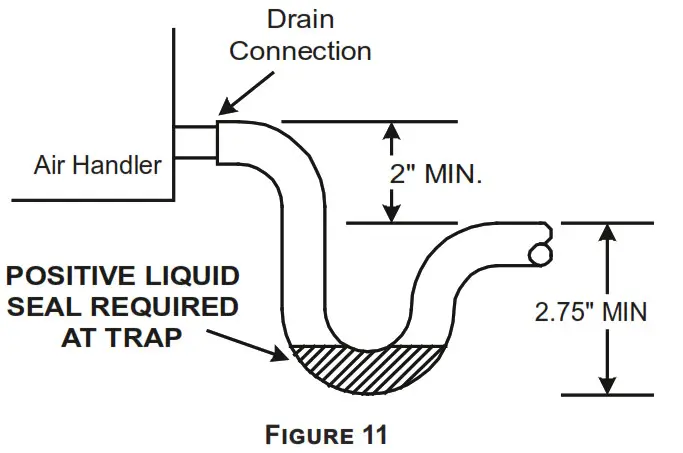
Insulate drain lines located inside the building or above a finished living space to prevent sweating. Install a condensate trap to ensure proper drainage.
NOTE: When units are installed above ceilings, or in other locations where damage from condensate overflow may occur, it is MANDATORY to install a field fabricated auxiliary drain pan under the coil cabinet enclosure.
The installation must include a “P” style trap that is located as close as is practical to the evaporator coil. See Figure 12 for details of a typical condensate line “P” trap.
NOTE: Units operating in high static pressure applications may require a deeper field constructed “P” style trap than is shown in Figure 12 to allow proper drainage and prevent condensate overflow.
NOTE: Trapped lines are required by many local codes. In the absence of any prevailing local codes, please refer to the requirements listed in the Uniform Mechanical Building Code.
A drain trap in a draw-through application prevents air from being drawn back through the drain line during fan operation thus preventing condensate from draining, and if connected to a sewer line to prevent sewer gases from being drawn into the airstream during blower operation.
Use of a condensate removal pump is permitted when necessary. This condensate pump should have provisions for shutting off the control voltage should a blocked drain
occur. A trap must be installed between the unit and the condensate pump.
IMPORTANT NOTE: The evaporator coil is fabricated with oils that may dissolve styrofoam and certain types of plastics. Therefore, a removal pump or float switch must not contain any of these materials.
Tip: Priming the “P” trap may avoid improper draining at the initial installation and at the beginning of the cooling season.
This air handler is designed for a complete supply and return ductwork system.
CAUTION
DO NOT OPERATE THIS PRODUCT WITHOUT ALL THE DUCTWORK ATTACHED.
To ensure correct system performance, the ductwork is to be sized to accommodate 350-450 CFM per ton of cooling with the static pressure not to exceed 0.5” in w.c. Refer to ACCA Manual D, Manual S and Manual RS for information on duct sizing and application. Flame retardant ductwork is to be used and sealed to the unit in a manner that will prevent leakage.
NOTE: A downflow application with electric heat must have an L-shaped sheet metal supply duct without any outlets or registers located directly below the heater.
9.1 Return Ductwork
DO NOT LOCATE THE RETURN DUCTWORK IN AN AREA THAT CAN INTRODUCE TOXIC, OR OBJECTIONABLE FUMES/ODORS INTO THE
DUCTWORK. The return ductwork is to be connected to the air handler bottom (upflow configuration).
Return Air Filters
NOTE: For AMVT24BP1400** only: If installing a filter, an external filter must be used when installing the unit in Horizontal Right, or if the side drain pan is not removed for Down Flow application. A filter will not fit on the internal filter rails in these applications.
Each installation must include a return air filter. This filtering may be performed at the air handler using the factory filter rails or externally such as a return air filter grille. When using the factory filter rails, a nominal 16x20x1”, 20x20x1” or 24x20x1” (actual dimension must be less than 23-½”x20”) filter can be installed on a B, C and D cabinet
respectively (the cabinet size is the seventh letter of the model number).
Electric Heat
Refer to the installation manual provided with the electric heat kit for the correct installation procedure. All electric heat must be field installed. If installing this option, the ONLY heat kits that are permitted to be used are the HKS and HKTSD series. Refer to the air handler unit’s Serial and Rating plate or the HKS and HKTSD specification sheets to determine the heat kits compatible with a given air handler. No other accessory heat kit besides the HKS and HKTSD series may be installed in these air handlers.
The heating mode temperature rise is dependent upon the system airflow, the supply voltage, and the heat kit size (kW) selected. Use data provided in Tables 5, 6, AND 7 to
determine the temperature rise (°F).
NOTE: For installations not indicated above the following formula is to be used:
TR = (kW x 3412) x (Voltage Correction) / (1.08XCFM)
Where: TR= Temperature Rise kW
= Heater Kit Actual kW
3412 = Btu per kW
VC* = .96 (230 Supply Volts)
= .92 (220 Supply Volts)
*VC (Voltage Correction)
= .87 (208 Supply Volts)
1.08 = Constant
CFM = Measured Airflow
NOTE: The Temperature Rise Tables can also be used to estimate the air handler airflow delivery. When using these tables for this purpose set the room thermostat to maximum heat and allow the system to reach steady state conditions. Insert two thermometers, one in the return air and one in the supply air. The temperature rise is the supply air temperature minus the room air temperature. Using the temperature rise calculated, CFM can be estimated from the TR formula above. See Service Manual for more information.
| CFM | HEAT KIT NOMINAL kW | |||||||
| 3 | 5 | 6 | 8 | 10 | 15 | 19/20 | 25 | |
| 800 | 12 | 19 | 23 | 31 | 37 | 56 | ||
| 1000 | 9 | 15 | 19 | 25 | 30 | 44 | ||
| 1200 | 8 | 12 | 15 | 21 | 25 | 37 | 49 | 62 |
| 1400 | 7 | 11 | 13 | 18 | 21 | 32 | 42 | 53 |
| 1600 | 6 | 9 | 12 | 15 | 19 | 28 | 37 | 46 |
| 1800 | 5 | 8 | 10 | 14 | 16 | 25 | 33 | 41 |
| 2000 | 5 | 7 | 9 | 12 | 15 | 22 | 30 | 37 |
230/1/60 SUPPLY VOLTAGE – TEMP. RISE °F
Table 7
| CFM | HEAT KIT NOMINAL kW | |||||||
| 3 | 5 | 6 | 8 | 10 | 15 | 19/20 | 25 | |
| 800 | 11 | 18 | 22 | 30 | 35 | 54 | ||
| 1000 | 9 | 14 | 18 | 24 | 28 | 42 | ||
| 1200 | 7 | 12 | 15 | 20 | 24 | 35 | 47 | 56 |
| 1400 | 6 | 10 | 13 | 17 | 20 | 30 | 40 | 48 |
| 1600 | 6 | 9 | 11 | 15 | 18 | 27 | 35 | 42 |
| 1800 | 5 | 8 | 10 | 13 | 16 | 24 | 31 | 37 |
| 2000 | 4 | 7 | 9 | 12 | 14 | 21 | 28 | 33 |
220/1/60 SUPPLY VOLTAGE – TEMP. RISE °F
Table 8
| CFM | HEAT KIT NOMINAL kW | |||||||
| 3 | 5 | 6 | 8 | 10 | 15 | 19/20 | 25 | |
| 800 | 10 | 17 | 21 | 28 | 33 | |||
| 1000 | 8 | 13 | 17 | 22 | 27 | 40 | ||
| 1200 | 7 | 11 | 14 | 19 | 22 | 33 | 45 | 56 |
| 1400 | 6 | 10 | 12 | 16 | 19 | 29 | 38 | 48 |
| 1600 | 5 | 8 | 10 | 14 | 17 | 25 | 33 | 42 |
| 1800 | 5 | 7 | 9 | 12 | 15 | 22 | 30 | 37 |
| 2000 | 4 | 7 | 8 | 11 | 13 | 20 | 27 | 33 |
208/1/60 SUPPLY VOLTAGE – TEMP. RISE °F
Table 9
Comfort Setting Menu Heater Kit Info
Comfort Setting Menu (CFS): There are 6 options available in the Comfort Setting Menu which impacts system target run time and electric heat functionality. Electric heat operation adjustments only apply if a communicating heat pump is installed. Comfort Setting Options 1 – 5 have set values for the System Target Runtime and option 6 enables additional menus to customize all comfort settings. See list below for the System Target Run times associated with the first 5 Comfort Settings. These first 5 options are setup to help satisfy the thermostat slower or faster based on the selection where option 1, with a 10 minute Target Runtime, is attempting to satisfy much faster than option 5, with a 30 minute Target Runtime.
System Target Runtime:
Comfort Setting Option 1) 10 Minute System Target Runtime
Comfort Setting Option 2) 15 Minute System Target Runtime
Comfort Setting Option 3) 20 Minute System Target Runtime
Comfort Setting Option 4) 25 Minute System Target Runtime
Comfort Setting Option 5) 30 Minute System Target Runtime
Electric Heat Adjustment: This system will automatically determine if the heat pump is capable of satisfying the thermostat in the selected System Target Runtime. If the heat pump is unable to satisfy in the selected time, electric heat settings will determine how many attempts should be given to the heat pump before temporarily locking it out and using the furnace. These electric heat settings also determine at what time the system should remove the temporary heat pump lockout and run the heat pump again. There are four adjustable items associated with back up electric heat operation control. In the same way as the System Target Time, each of these items have defaulted values for Comfort Settings 1 – 5. Only when Comfort Setting 6 is selected will each item be available for full adjustment.
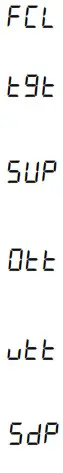
Stage Up Percent (7 segment menu SUP): This is a value that determines how far past the target runtime the system should continue running the heat pump before transitioning to the furnace. For example, assume this menu was set to 20% with a target runtime of 20 minutes. If the thermostat did not remove the heating call after 20 minutes, the system would allow for an additional 20% heat pump run (20% of the 20 minute target is an additional 4 minutes). In this case, the system would turn on back up electric heat after 24 minutes if the thermostat call was still present. Each time this occurs, the system records this as a strike against the heat pump (the strike is important when looking at the Over Target Threshold).
Over Target Threshold (7 segment menu Ott): If the heat pump has consecutively activated back up electric heat for the selected Over Target Threshold amount of times, meaning for this many consecutive cycles it has been unable to satisfy the target time by itself, then the heat pump will be temporarily locked out and the furnace will become the primary heat source.
Stage Down Percent (7 segment menu SdP): This only applies when the heat pump and back up electric heat are activated on initial start-up. In this case, the system will try to determine when the best time to operate the heat pump individually again. To determine this, the system looks at how easily the air handler is able to satisfy the thermostat using the heat pump with back up electric heat. Assume this setting is 15% and the target time is 20 minutes If the heat pump with back up electric heat can satisfy the thermostat in less than 17 minutes (20 minutes – 15% = 17 minutes) then the algorithm records a strike against the air handler (this strike is important when looking at the Under Target Threshold).
| Model | HEATER KIT (Kw) | ||||||||
| 3 | 5 | 6 | 8 | 10 | 15 | 19 | 20 | 25 | |
| AMVT24BP14 | 550 | 650 | 700 | 800 | 850 | 875 | |||
| AMVT30BP14 | 550 | 650 | 700 | 800 | 875 | 1050 | |||
| AMVT36BP14 | 630 | 650 | 700 | 800 | 875 | 1050 | |||
| AMVT36CP14 | 735 | 810 | 935 | 1020 | 1145 | 1345 | |||
| AMVT42CP14 | 735 | 810 | 935 | 1020 | 1145 | 1345 | |||
| AMVT48CP14 | 880 | 880 | 1045 | 1200 | 1420 | 1480 | |||
| AMVT48DP14 | 1040 | 1170 | 1260 | 1300 | 1595 | 1595 | |||
| AMVT60DP14 | 1135 | 1265 | 1375 | 1455 | 1815 | 1860 | 1925 | ||
*Airflows shown are to be considered the absolute minimum allowable for the Air handler and Heat kit combination. The minimum airflow does not represent the recommended airflow by the manufacturer. When selecting a heater kit, the Minimum Blower Setting (M.B.S.) or speed tap listed on the unit’s nameplate should be followed.
Minimum CFM Required for Heater Kits
Table 10
Under Target Threshold (7 segment menu Utt): If the air handler is able to satisfy the thermostat using the heat pump with back up electric heat for the selected number of consecutive cycles the electric heat operation will be temporarily removed. The heat pump will then be used during the next cycle. If the heat pump can satisfy the thermostat in less than the System Target Runtime the back up heat operation will be completely removed and the heat pump will become the primary heat source again. If it fails to do so, the strike count against the furnace will be reset and the furnace will remain the temporary primary heat source until the Under Target Threshold is reached again.
The system will automatically make adjustments in an attempt to satisfy the thermostat as close to this target runtime as possible. After a power cycle or mode change (cooling to heating or heating to cooling) the system will run full capacity for the selected mode during the first thermostat call. Based on the selected target runtime and how long the initial cycle takes to satisfy the thermostat, the control algorithm will adjust the system stage times for a 2 stage unit or the capacity demand percentage for an inverter / modulating unit for the next cycle.
NOTE: actual run times may change depending on variations of load throughout the day.
The following table shows the default values for all Comfort Setting Options (1 – 5):
| Comfort Setting Option | Target Time (Minutes) | Stage Up Percentage (%) | Stage Down Percentage (%) | Over Target Threshold (Strike Count) | Under Target Threshold (Strike Count) |
| 1 | 10 | 20 | 20 | 2 | 10 |
| 2 | 15 | 20 | 20 | 4 | 8 |
| 3 | 20 | 20 | 20 | 6 | 6 |
| 4 | 25 | 20 | 20 | 8 | 4 |
| 5 | 30 | 20 | 20 | 10 | 2 |
The following table shows the ranges for each of item when the adjustable Comfort Setting Option 6 is selected. The table shows the minimum value, the maximum value and the defaulted value. All items can be adjusted up or down by increments of 1 which provides full flexibility for all items.
NOTE: It is critical that these numbers be set properly.
If Comfort Setting option 3 is desired but a target time of 60 is preferred, select Comfort Setting Option 6 to enable all the adjustable menus, set the Target Time to 60 and make sure the other menus are set to match that of Comfort Setting Option 3.
| Menu | Minimum Value | Maximum Value | Default Value |
| Target Time (t9t) | 1 minute | 240 minutes | 60 minutes |
| Stage Up Percent (SUP) | 0% | 100% | 20% |
| Stage Down Percent (SdP) | 0% | 100% | 20% |
| Over Target Threshold (Ott) | 1 strike | 254 strikes | 20 strikes |
| Under Target Threshold (Utt) | 1 strike | 254 strikes | 20 strikes |
Electrical and Control Wiring
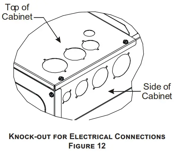
IMPORTANT: All routing of electrical wiring must be made through provided electrical knockouts. Do not cut, puncture or alter the cabinet for electrical wiring.
WARNING![]() HIGH VOLTAGE
HIGH VOLTAGE
DISCONNECT ALL POWER BEFORE SERVICING OR INSTALLING THIS UNIT. MULTIPLE POWER SOURCES MAY BE PRESENT. FAILURE TO DO SO MAY CAUSE PROPERTY DAMAGE, PERSONAL INJURY OR DEATH.![]() WARNING
WARNING
HIGH VOLTAGE! TO AVOID PROPERTY DAMAGE, PERSONAL INJURY OR DEATH DUE TO ELECTRICAL SHOCK, THIS UNIT MUST HAVE AN UNINTERRUPTED, UNBROKEN ELECTRICAL GROUND. THE ELECTRICAL GROUND CIRCUIT MAY CONSIST OF AN APPROPRIATELY SIZED ELECTRICAL WIRE CONNECTING THE GROUND LUG IN THE UNIT CONTROL BOX TO THE BUILDING ELECTRICAL SERVICE PANEL. OTHER METHODS OF GROUNDING ARE PERMITTED IF PERFORMED IN ACCORDANCE WITH THE NATIONAL ELECTRIC CODE (NEC)/AMERICAN NATIONAL STANDARDS INSTITUTE (ANSI)/NATIONAL FIRE PROTECTION ASSOCIATION (NFPA) 70 AND LOCAL/STATE CODES. IN CANADA, ELECTRICAL GROUNDING IS TO BE IN ACCORDANCE WITH THE CANADIAN ELECTRIC CODE (CSA) C22.1.
12.1 Building Electrical Service Inspection
This unit is designed for single-phase electrical supply only. DO NOT OPERATE ON A THREE-PHASE POWER SUPPLY. Measure the power supply to the unit. The supply voltage must be measured and be in agreement with the unit nameplate power requirements and within the range shown.
12.2 Wire Sizing
Wire size is important to the operation of your equipment.
Use the following check list when selecting the appropriate wire size for your unit.
- Wire used must carry the Minimum Circuit Ampacity (MCA) listed on the unit’s Series and Rating Plate.
- Refer to the NEC (USA) or CSA (Canada) for wire sizing. The unit MCA for the air handler and the optional electric heat kit can be found on the unit Series and Rating Plate.
- Wire must be sized to allow no more than a 2% voltage drop from the building breaker/fuse panel to the unit.
- Wires with different insulation temperature rating have varying ampacities – be sure to check the temperature rating used
Refer to the latest edition of the National Electric Code or in Canada the Canadian Electric Code when determining the correct wire size.
12.3 Maximum Overcurrent Protection (MOP)
Every installation must include an NEC (USA) or CEC (Canada) approved overcurrent protection device. Also, check with local or state codes for any special regional requirements.
Protection can be in the form of fusing or HACR style circuit breakers. The Series and Rating Plate provides the maximum overcurrent device permissible.
NOTE: Fuses or circuit breakers are to be sized larger than the equipment MCA but not to exceed the MOP.
| Nominal Input | Minimum Voltage | Maximum Voltage |
| 208-230 VAC | 197 | 253 |
Electrical Voltage
Table 11
12.4 Electrical Connections – Supply Voltage
CAUTION
FIRE HAZARD!
TO AVOID THE RISK OF PROPERTY DAMAGE, PERSONAL INJURY OR FIRE, USE ONLY COPPER CONDUCTORS.
IMPORTANT NOTE: Use copper conductors only from disconnect or electrical panel to the air handler.
Knockouts are provided on the air handler top panel and sides of the cabinet to allow for the entry of the supply voltage conductors, as shown in Figure 13. Separate knockouts must be used for two circuit heat kits. Unless Single Point Wiring Kit (SPW-01) is used. If the knockouts on the cabinet sides are used for electrical conduit, an adapter ring must be used in order to meet UL1995 safety requirements. An NEC or CEC approved strain relief is to be used at this entry point. Some codes/municipalities require the supply wire to be enclosed in conduit. Consult your local codes.
12.4.1 Air Handler Only (Non-Heat Kit Models)
IMPORTANT: Installation of Air Handler must follow any local codes/regulations. The manufacture recommends that when a heater kit is not installed, a field supplieddisconnect switch or breaker should be installed in the electrical circuit that will allow power to be shut-off for service or maintenance.
The building supply connects to the stripped black and red wires contained in the air handler electrical compartment cavity. A ground screw is also contained in this area.
Attach the Supply wires to the air handler conductors as shown in the unit wiring diagram using appropriately sized solderless connectors or other NEC or CEC approvedmeans.
12.4.2 Air Handler – Non-Circuit Breaker Heat Kits
A terminal block is provided with the HKS and HKTSD kit to attach the power supply and air handler connections.
Follow the HKS and HKTSD Installation Manual and wiring diagram for complete wiring details.
12.4.3 Air Handler With Circuit Breaker Heat Kit
The air handler has soft plastic cover on the upper access panel and can be removed to allow the heater kit circuit breaker to be installed. The circuit breakers have lugsfor power supply connection. See the HKS and HKTSD Installation Instructions for further details.
12.5 Low Voltage Connections
Several combinations of low voltage schemes are possible, depending on the presence of a heat kit and whether the heat kit is single-stage or multi-stage, whether the outdoor
section is an air conditioner or heat pump, and whether the outdoor section is single-stage or two-stage. The 24V-control voltage connects the air handler to the room thermostat and condenser. Low voltage wiring must be copper conductors. A minimum of 18AWG must be used for installations up to 100 feet. Low voltage wiring must be connected through the top of the cabinet or either side.
See the “Thermostat Wiring” section of this manual for typical low voltage wiring connections.
12.5.1 Thermostats
Second-stage heat can be accomplished by a multi-stage heating thermostat or the addition of an outdoor thermostat as shown in wiring schematics on page 19. Follow the
thermostat manufacturer’s instructions for installation.
Cool Cloud HVAC Phone Application
NOTE: This equipment has been tested and found to comply with the limits for a Class B digital device, pursuant to part 15 of the FCC Rules. These limits are designed to provide reasonable protection against harmful interference in a residential installation. This equipment generates, uses and can radiate radio frequency energy and, if not installed and used in accordance with the instructions, may cause harmful interference to radio communications. However, there is no guarantee that interference will not occur in a particular installation. If this equipment does cause harmful interference to radio or television reception, which can be determined by turning the equipment offand on, the user is encouraged to try to correct the interference by one or more of the following measures:
- Reorient or relocate the receiving antenna.
- Increase the separation between the equipment and receiver.
- Connect the equipment into an outlet on a circuit different from that to which the receiver is connected.
- Consult the dealer or an experienced radio/ TV technician for help.
Actual screens may look different based on the mobile device being used.
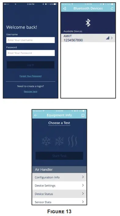
This air handler is Bluetooth ready and functions with the Cool Cloud HVAC phone application designed to improve the contractor’s setup / diagnostic experience. Users can see specific model information, review active diagnostic error codes, observe system menu testing of all operational modes (heat / cool / fan) directly from the phone. The phone application is also capable of directly updating the air handler software anytime updates are available. The application will automatically notify the user.
NOTE: The software update may take up to 20 minutes to complete.
Quick Start Guide for Communication Outdoor Units
EXTREMELY IMPORTANT: For all cooling calls the system only requires a single Y input from the thermostat. For all heating calls (including applications with backup electric heater kits) the system only requires a single W input from the thermostat. Internal algorithms will control all available cooling and heating stages based on these inputs. Any single-stage 24VAC thermostat can be used. For proper operation, the thermostat must be setup to control a single stage AC outdoor unit and to control single stage electric heat operation. The control board does not accommodate an O wire thermostat input (reversing valve signal).
If a heat pump is installed, the thermostat should be setup as stated above. Setting the thermostat for the heat pump control or multistage control may result in incorrect performance.
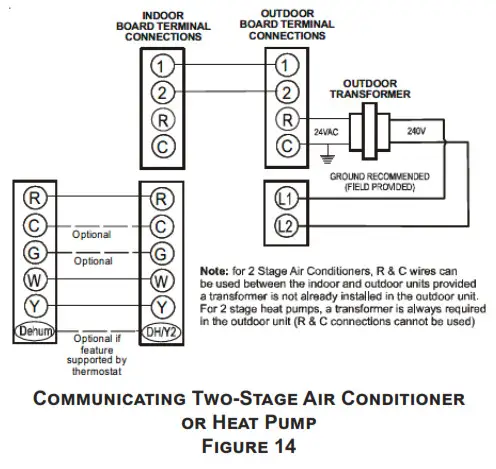
- Connect all necessary thermostat wires to the thermostat connector on the air handler control as instructed by the applicable wiring diagrams shown in this section.
- Connect the 1 & 2 wires between the indoor and outdoor unit for communicating operation.
NOTE: Verify two stage outdoor units include a 24VAC transformer (for outdoor control board power). Two stage outdoor units may not behave properly without this 24 VAC transformer.
- Download the Cool Cloud HVAC phone application for charging and to configure / test system.
NOTE: When new versions of Bluetooth Communication Software and Air Handler Control Software are available, the phone application notifies the user. Software updates are classified as either optional or mandatory and installed by using the phone application. Ensure all mandatory software updates and install if necessary.
14.1 Charging
- Two-stage outdoor units using the Cool Cloud HVAC application:
a. Using the cooling icon after entering the outdoor unit menus, energize the outdoor unit at 49% capacity or lower.
b. Charge the outdoor unit as required using the charging information provided with the outdoor equipment.
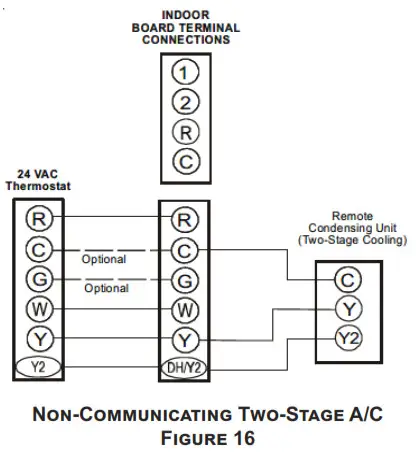
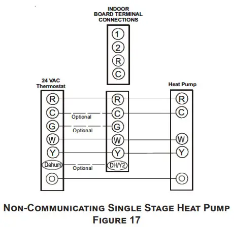
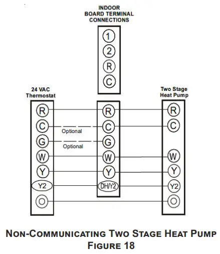
Quick Start Guide for Non-Communicating Outdoor Units
When setting up a Comfort Bridge air handler for use with a Non-Communicating outdoor unit you must set airflow in the “ton” menu on the PCB or in the Cool Cloud HVAC APP. Failure to do so will result in the air handler PCB displaying “IdL” and the blower will not operate with a call for cooling. The Board does not need to be replaced, you MUST set the airflow first.
EXTREMELY IMPORTANT: For two stage electric heat kit control the system only needs a single W input. Internal algorithms will control staging automatically based on the single W input. For non-communicating outdoor unit wiring, see instructions below:
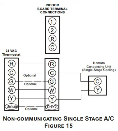
- Use the wiring diagrams on the next page to connect low voltage thermostat wires.
NOTE: When installing the air handler with a noncommunicating heat pump, wire directly to the “O” terminal on the non-communicating heat pump. See the following figures.


- Download the Cool Cloud HVAC phone application.
NOTE: When new versions of Bluetooth Communication Software and Air Handler Control Software are available, the phone application notifies the user. Software updates are classified as either optional or mandatory and installed by using the phone application. Ensure all mandatory software updates have been installed. Review notes for optional software updates and install if necessary. - Go to the Non-Comm Outdoor Setting Menu (
 ) using the on board push buttons or the Cool Cloud HVAC phone application. Select “
 ” for single stage Air Conditioners, “
 ” for single stage Heat Pumps, “” for two stage Air Conditioners and “
 ” for 2 stage Heat Pumps.
 - Go to the Tonnage Units Menu (
 ) and select the tonnage value that corresponds to the desired airflow for the outdoor unit. See the following table.
NOTE: For the two stage non-communicating outdoor units, system will stage airflow automatically for low stage operation.
| Tonnage Selection | Airflow | Tonnage Selection | Airflow | Tonnage Selection | Airflow | Tonnage Selection | Airflow |
| 1 | 400 | 2.3 | 920 | 3.6 | 1440 | 4.9 | 1960 |
| 1.1 | 440 | 2.4 | 960 | 3.7 | 1480 | 5 | 2000 |
| 1.2 | 480 | 2.5 | 1000 | 3.8 | 1520 | 5.1 | 2040 |
| 1.3 | 520 | 2.6 | 1040 | 3.9 | 1560 | 5.2 | 2080 |
| 1.4 | 560 | 2.7 | 1080 | 4 | 1600 | 5.3 | 2120 |
| 1.5 | 600 | 2.8 | 1120 | 4.1 | 1640 | 5.4 | 2160 |
| 1.6 | 640 | 2.9 | 1160 | 4.2 | 1680 | 5.5 | 2200 |
| 1.7 | 680 | 3 | 1200 | 4.3 | 1720 | 5.6 | 2240 |
| 1.8 | 720 | 3.1 | 1240 | 4.4 | 1760 | 5.7 | 2280 |
| 1.9 | 760 | 3.2 | 1280 | 4.5 | 1800 | 5.8 | 2320 |
| 2 | 800 | 3.3 | 1320 | 4.6 | 1840 | 5.9 | 2360 |
| 2.1 | 840 | 3.4 | 1360 | 4.7 | 1880 | 6 | 2400 |
| 2.2 | 880 | 3.5 | 1440 | 4.8 | 1920 |
Table 12
NOTE: The system will not provide airflows above the max Airflow Value.
NOTE:
- Airflow data indicated is at 230V without air filter in place.
- The cooling/heat pump speed tap should be selected based on the AHRI rating. Otherwise, select a speed tap that provides a minimum 350 CFM per outdoor ton. For satisfactory operation, external static pressure must not exceed 0.5” WC.
EXAMPLE: For a 2 ton outdoor, 1.6T 10% trim is the lowest valid speed for AMVT24BP1400 (704 SCFM at 0.5” WC).Outdoor Unit Tonnage 1.5 2 2.5 3 3.5 4 5 Minimum
Cooling/Heating CFM @ .5″ WC ESP525 700 875 1050 1225 1400 1750 Table 13
- Use the CFM adjustment factors of 0.98 for horizontal left and 0.96 for horizontal right and downflow orientations.
Model Max CFM AMVTC25B14 AMVTC29B14 AMVTC35B14 AMVTC37B14 1200 AMVTC33C14 1300 AMVTC31C14 AMVTC37C14 AMVTC39C14 1600 AMVTC37D14 AMVTC49C14 1800 AMVTC49D14 AMVTC59C14 1900 AMVTC59D14 AMVTC61D14 2100 Table 14
- Use the Cool Cloud HVAC phone application to configure/test air handler operations.
NOTE: The phone application cannot test a non- communicating outdoor unit. The thermostat will be required for outdoor unit testing.
15.1 Electric Heater Kit Testing
- Select the electric heat icon after entering the air handler menus while using the Cool Cloud phone application.
- Select any value less than 50% for low stage operation and any value greater than 50% for high stage operation.
- Confirm thermostat heating and cooling calls function properly for high stage operation.
| MODEL NAME | MAX CFM |
| AMVT24BP1400 | 1275 |
| AMVT30BP1400 | 1450 |
| AMVT36BP1400 | |
| AMVT36CP1400 | 1575 |
| AMVT42CP1400 | |
| AMVT48CP1400 | 1700 |
| AMVT48DP1400 | 1800 |
| AMVT60DP1400 | 2200 |
Table 15
Dehumidification
Dehumidification allows the air handler’s circulator blower to operate at a reduced speed during a combined thermostat call for cooling and a dehumidification call from the thermostat or humidistat. This lower blower speed increases dehumidification of the conditioned air as it passes through the indoor coil. The control board is equipped with a 24 volt dehumidification input (DH) located on the thermostat wiring connector. The terminal can be configured to enable dehumidification when the input is energized or de-energized. When using an external Dehumidistat, connect it between the R and DH terminals. If the humidistat closes on humidity rise or the thermostat energizes this terminal when dehumidification is required, set the control board Dehu Logic Menu (![]() ) to “
) to “![]() ” using the push buttons or Cool Cloud HVAC phone application. If the humidistat opens on humidity or the thermostat deenergizes this terminal when dehumidification is required, set the Dehu Logic Menu to “
” using the push buttons or Cool Cloud HVAC phone application. If the humidistat opens on humidity or the thermostat deenergizes this terminal when dehumidification is required, set the Dehu Logic Menu to “![]() ” using the push buttons or Cool Cloud HVAC phone application.
” using the push buttons or Cool Cloud HVAC phone application.
Auxiliary Alarm Switch
The control is equipped with a 24VAC Aux Alarm to be used for a condensate switch install (designated by CONDENSATE IN/OUT on the control). By default, the
connected AUX switch is normally closed and opens when the water level in the evaporator coil base pan reaches an undesirable level. The control responds by displaying
a “![]() ” error code and turning off the outdoor condensing unit. If the AUX switch is detected to be in the closed position for 30 seconds, normal operation resumes and the error message is no longer displayed.
” error code and turning off the outdoor condensing unit. If the AUX switch is detected to be in the closed position for 30 seconds, normal operation resumes and the error message is no longer displayed.
Start-Up Procedure
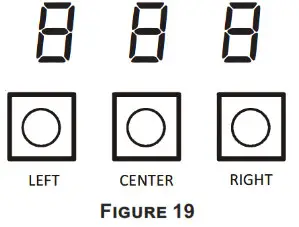
The air handler includes three on-board push buttons allowing users to navigate indoor and outdoor system menus. The Right and Left buttons allow the user to scroll through the main menus and to then scroll through available options within specific menus. The Center button is used to enter into a main menu and to then permanently
select options within those menus.
NOTE: After scrolling to the desired option within a menu, that option may be flashing on the 7-segment displays. This indicates the option has not been officially selected. Pressing the Center button two times will select that option. The first press will stop the flashing. The second will make the selection official and return you to the main menu.
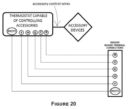
Accessory Control (Humidifiers, Dehumidifiers, Ventilators)
If an external humidifier, dehumidifier or ventilator is installed, it may require airflow from the HVAC system to function properly.
- Make sure the installed 24VAC thermostat is capable of controlling the accessory or accessories.
- Connect the appropriate accessory control wires to the accessory devices from the thermostat (see thermostat manual for connection and setup instructions).
- If the thermostat is capable of providing a continuous fan call (G signal) during accessory operation: Make sure to connect the thermostat G terminal to the G terminal on the indoor unit. Setup thermostat to ensure G signal is energized during accessory operation.

- Select the appropriate fan only airflow for the accessory using the indoor unit push button menus or the Cool Cloud HVAC phone application.
- Using the thermostat, independently test each accessory in addition to the independently testing continuous fan mode.
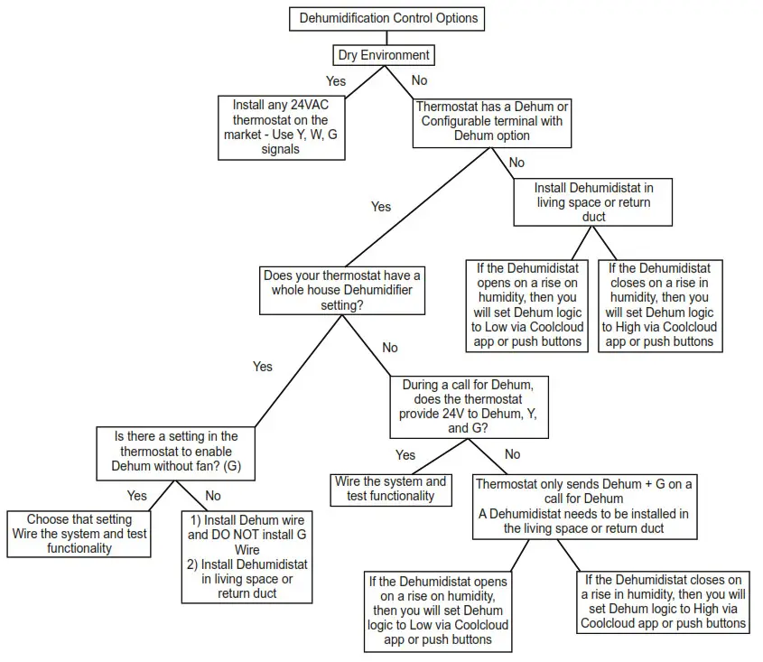
Dehumidification Control Options
Key Mitigations:
- Full featured TS (degum & overcool)
- Connect G and degum wire correctly
- Dehumidistat
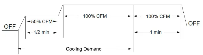
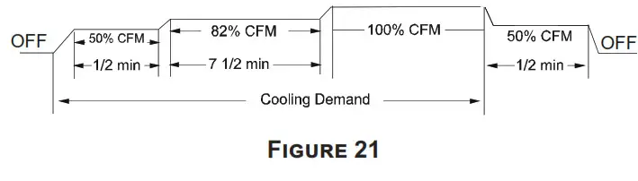
Ramping Profiles
The variable-speed circulator offers four different ramping profiles. These profiles may be used to enhance cooling performance and increase comfort level. Select the desired
ramping profile using the Cool Cloud phone application or the push button menus.
- Profile A provides only an OFF delay of one (1) minute at 100% of the cooling demand airflow.

- Profile B ramps up to full cooling demand airflow by first stepping up to 50% of the full demand for 30 seconds. The motor then ramps to 100% of the required airflow. A one (1) minute OFF delay at 100% of the cooling airflow.

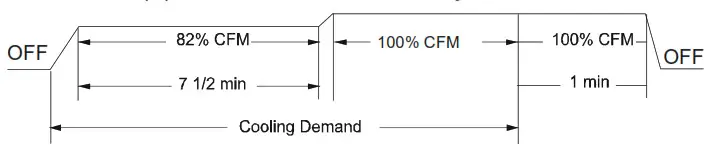
- Profile C ramps up to 82% of the full cooling demand airflow and operates there for approximately 7 1/2 minutes. The motor then steps up to the full demand airflow. Profile C also has a one (1) minute 100% OFF delay.

- Profile D ramps up to 50% of the demand for 1/2 minute, then ramps to 82% of the full cooling demand airflow and operates there for approximately 7 1/2 minutes. The motor then steps up to the full demand airflow. Profile D has a 1/2 minute at 50% airflow OFF delay.


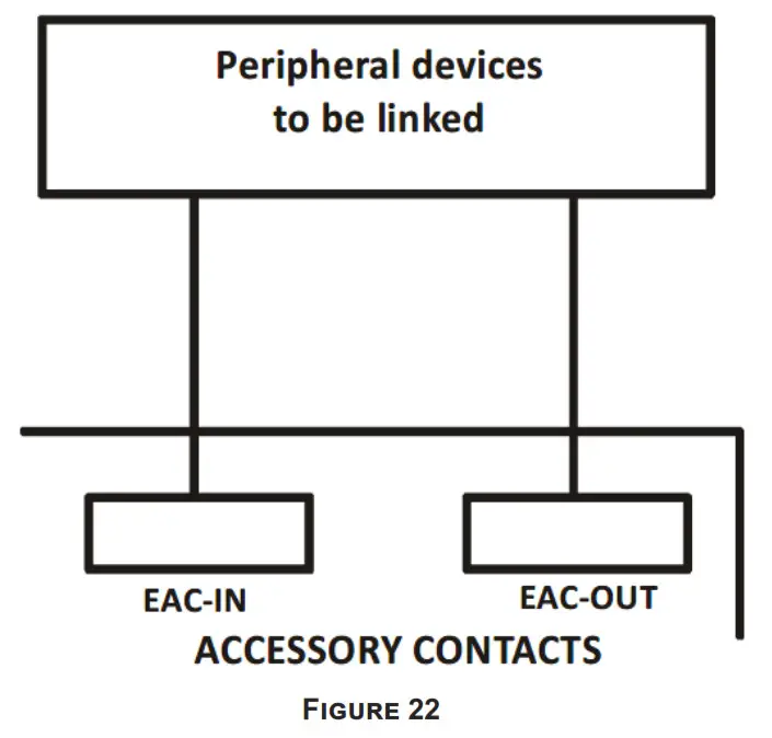
Electric Air Cleaner Warning
The control is equipped with an Accessory Relay and a pair of ¼ inch accessory terminals which is normally open, labeled EAC-IN and EAC-OUT (see accessory contacts graphic). The Accessory Relay is configured to close anytime the blower is running. A closed relay means the two terminals will have continuity between them (the control
does not energize these contacts). It is recommended to utilize 24VAC with these terminals and limit the current to 1A.
Achieving 1.4% Low Leakage Rate
Ensure all the gaskets remain intact on all surfaces as shipped with the unit. These surfaces are areas between the upper tie plate and blower access panel, blower access and coil access panels, and between the coil access and filter access panels. Ensure upon installation, that the plastic breaker cover is sitting flush on the blower access panel and all access panels are flush with each other and the cabinet. With these requirements satisfied, the unit achieves less than 1.4% airflow leakage when tested in accordance with ASHRAE Standard 193.
Start-Up Procedure![]() WARNING
WARNING![]() HIGH VOLTAGE
HIGH VOLTAGE
DISCONNECT ALL POWER BEFORE SERVICING OR INSTALLING THIS UNIT. MULTIPLE POWER SOURCES MAY BE PRESENT. FAILURE TO DO SO MAY CAUSE PROPERTY DAMAGE, PERSONAL INJURY OR DEATH.
- Prior to start-up, ensure that all electrical wires are properly sized and all connections are properly tightened.
- All panels must be in place and secured. For Air Tight application, gasket must be positioned at prescribed locations to achieve 1.4% leakage.
- Tubing must be leak free.
- Condensate line must be trapped and pitched to allow for drainage.
- Low voltage wiring is properly connected.
- Auxiliary drain is installed when necessary and pitched to allow for drainage.
- Unit is protected from vehicular or other physical damage.
- Return air is not obtained from, nor are there any return air duct joints that are unsealed in, areas where there may be objectionable odors, flammable vapors or products of combustion such as carbon monoxide (CO), which may cause serious personal injury or death.
Regular Maintenance
The only item required to be maintained on a regular basis by the user is the circulating air filter(s). Filter should be cleaned or replaced regularly, typically once per month. A
certified service technician must perform all other services.
IMPORTANT NOTE: If thumb screws are used to access the filter, ensure the washer installed on the screw behind the access panel remains in place after re-installation.
Air Handler Troubleshooting Matrix
| Symptoms of Abnormal Operation | Diagnostic / Status LED Codes | Fault Description | Possible Causes | Corrective Actions |
| No outdoor unit operations |  | Communication error with outdoor unit | Improper low voltage wiring between the indoor and outdoor unit Outdoor control board lost power duirng operation | Locate and correct improper low voltage wiring issue Identify reason outdoor control board lost power during operation |
| No Air Handler operation | Open fuse | Short in low voltage wiring | Locate and correct short in low voltage wiring Replace fuse with 3-amp automotive type | |
| No Air Handler operation |  | Auxiliary switch (condensate switch) open or open fuse | High water level in the evaporation coil or short in low voltage wiring | Check evaporator drain pan, trap, piping Replace fuse with 3-am automotive type |
| No Air Handler operation | Data not yet on network | No network data | Populate shared data set using memory card | |
| No Air Handler operation | Invalid memory card data | Air Handler blower does not contain an appropriate shared data set | Populate correct shared data using memory card | |
| Operation different than expected or no oper |  | Invalid memory card data | Shared data set on memory card has been rejected by integrated control module | Verify shared data set is correct for the specifc model. Re-populate data using correct memory card if required |
| No Air Handler operation |  | Circulator blower motor not running with demand present | Loose or disconnected wiring connection at circulator motor power leads Open circuit in inductor or loose wiring connection at inductor (3/4 Hp and 1 Hp models only) Failed circulator blower motor | Tighten or correct wiring connection Verify continuous circuit through inductor. Replace if open or short circuit Check circulator blower motor |
| No Air Handler operation |  | Integrated control module has lost communications with circulator blower motor | Loose wiring connection at circulator motor control leads Failed circulator blower motor Failed integrated control module | Tighten or correct wiring connection Check circulator blower motor, replace if necessary Check integrated control module, replace if necessary |
| No Air Handler operation | Circulator blower motor horse power in shared data set does not match circulator blower motor horse power | Incorrect circulator blower motor in Air Handler Incorrect shared data set in integrated control module | Verify circulator blower if motor horse power is the same specified for the specific Air Handler model, replace if necessary Verify shared data set is correct for the specific model, re-populate data using correct memory card if required | |
| Air Handler operates at reduced performance Airflow delivered is less than expected | Circulator blower motor is operating in a power, temperature, or speed limiting condition | Blocked falters Restrictive or undersized ductwork High ambient temperatures | Check filters for blockage, clean falters or remove obstruction Check ductwork for blockage, remove obstruction and verify all registers are fully open Verify ductwork is appropriately sized for system and resize/replace ass needed |
| Symptoms of Abnormal Operation | Diagnostic / Status LED Codes | Fault Description | Possible Causes | Corrective Actions |
| No Air Handler operation |  | Circulator blower motor senses a loss of rotor control Circulator blower motor senses high current | Abnormal motor loading, sudden change in speed or torque, sudden blockage of air handler air inlet or outlet | Check filters, filter grills/registers, duct system and air handler inlet/outlet for blockages |
| No Air Handler operation | Circulator blower motor fails to start 10 consecutive times | Obstruction in circulator blower housing Seized Circulator blower motor bearings Failed circulator blower motor | Check circulator blower for obstructions Remove and repair/replace wheel/motor if necessary Check circulator blower motor shaft rotation and motor, replace motor if necessary | |
| No Air Handler operation |  | Circulator blower motor shuts down for over or under voltage condition Circulator blower motor shuts down due to over temperature condition on power module | High or low AC line voltage to air handler High ambient temperatures | Check power to air handler Verify line voltage is within the range specified on the rating plate |
| No Air Handler operation | Circulator blower motor does not have enough information to operate properly Motor fails to start 40 consecutive times | Error with integrated control module shared data | Verify control is populated with the correct shared data | |
| Air Handler operates at reduced performance or operates on low stage when high stage is expected | Airflow is lower than demanded | Blocked filters or restrictive ductwork Undersized ductwork | Check filters for blockage, clean filters or remove obstruction Check ductwork for blockage, remove obstruction and verify all registers are fully open Verify ductwork is appropriately sized for system, resize/replace ductwork if necessary |
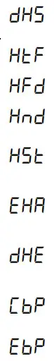
Air Handler Display
| LED Display | Menu Description |
 | View 6 most recent fault codes and Clear Fault Codes if desired (furnace) |
| Restart communications between the indoor and outdoor unit. | |
| Control Firmware Revision Number | |
| Control Shared Data Revision Number | |
| Constant Fan Speed as percent of maximum airflow. Default = 30% | |
| Electric Heater Kit Wattage (kW) | |
| Electric Heat Off Delay (seconds) | |
| Electric Heat On Delay (seconds) | |
| Electric Heat Airflow Trim (percentage) | |
| Percentage of high stage electric heating airflow to run duirng low stage electric heat operation | |
| 1 = system will try to satisfy the thermostat quickly. 5 (default) = system will try to satsify the thermostat more slowly. | |
 | Select “ |
 | Select number of stages for the non-communicating outdoor unit. ( |
 | Indoor Airflow for non-communicating outdoor units. (values based on 400CFM per ton) (default = 3.0 Ton) |
| Cooling Airflow Trim (default 0%) | |
| Cooling Airflow Profile setting (default = profile D shown as 4) | |
| Cooling Airflow On Delay Time (default = 5 seconds) | |
| Cooling Airflow Off Delay Time. (default = 60 seconds) | |
| Percentage of high stage cooling airflow to run during low stage operation. (default = 70%) | |
| Electric heat operation during defrost. 1 = low stage 2 (default) = high stage | |
 | Heat Pump Indoor Airflow Trim (default = 0%) |
| Heat Pump Heating Airflow Off Delay Time (default = 60 seconds) | |
| Heat Pump Heating Airflow On Delay Time (default = 5 seconds) | |
| Percentage of high stage heat pump heating airflow to run during low stage operation. (defaullt = 70%) | |
| When heat pump heating and electric heat are running at the same time, this percentage is used for additional airflow trim | |
| Enables or disables dehumidification feature in the outdoor unit. (default = Enabled) | |
| Balance point temperature. The Compressor will not operate below temperature. (Default = 0°F) | |
| Backup Heat Balance Points | |
| Compressor run time between defrost cycles. (default = 30 minutes) (2 stage units) | |
| Compressor off delay at the beginning and end of a defrost cycle. (default = 30 seconds) |
| LED Display | Menu Description |
 | View 6 most recent fault codes and Clear Fault Codes if desired (outdoor communicating units) |
| Menu is enabled if the | |
| Menu is enabled if the | |
| Menu is enabled if the | |
| Menu is enabled if the | |
| Menu is enabled if the |
| LED Display | Description of System Status |
 | Idle |
| Constant Fan | |
| Compressor Cooling, Single-Stage (non-comm units) | |
| Compressor Cooling, Low Stage (non-comm units) | |
| Compressor Cooling, High Stage (non-comm units) | |
| Compressor Cooling, Low Stage (comm units) | |
| Compressor Cooling, High Stage (comm units) | |
| Compressor Heat, Single-Stage (non-comm. units) | |
| Compressor Heat, Low Stage (non-comm units) | |
| Compressor Heat, High Stage (non-comm units) | |
| Compressor Heat, Low Stage (Comm Units) | |
| Compressor Heat, High Stage (Comm Units) | |
| Electric Heat, Single Stage | |
| Electric Heat, Low Stage | |
| Electric Heat, High Stage | |
| Defrost, Single Stage Electric Heat (non-comm units) | |
| Defrost, Low Stage Electric Heat | |
| Defrost, High Stage Electric Heat | |
| Dehumidification |
* If a system is a heat pump connected legacy, then a DFT will show on the board in 2 instances.
- If the heat pump calls for a defrost, Y and a W will be energized resulting in a DFT code on the air-handler display.
- If the heat pump calls for auxiliary heat, Y and a W will be energized resulting in a DFT code on the air-handler display.
Air Flow Label
Menu Navigation and Selection Instructions
Using Phone Application over Bluetooth Network:
- Connect to the air handler (instructions provided by phone during connection process).
- Select desired settings menu
- Select item that requires adjustment and make necessary selection
- Submit Changes
Using On-Board Push Buttons:
- Use the Right and Left Buttons to scroll between menus
- Use the Center Button to select desired menu when menu code is shown on 7-segment displays
- Use the Left and Right Buttons to scroll through options within the desired menu (the display will flash while scrolling through options for selection)
- Use the Center Button to select the displayed option (when selected the display will stop flashing)
- Use the Center Button to finalize selection and return to the main menu
| Profiles | Pre-Run | Short-Run | OFF Delay |
| 1 | ——– | ——– | 60 sec/100% |
| 2 | ——– | 30 sec/50% | 60 sec/100% |
| 3 | ——– | 7.5 min/82% | 60 sec/100% |
| 4 | 30 sec/50% | 7.5 min/82% | 60 sec/100% |
Airflow Settings Instructions
- For non-communicating installations, select the type of unit installed in the OdS menu (1AC = single-stage air conditioner,
1HP = single-stage heat pump, 2AC = 2 stage air conditioner,
2HP = 2 stage heat pump) Default = OFF (no outdoor unit). - Use the Tonnage Menu (ton ) to select Cooling/Heat Pump Airflow (non-communicating installation). Tonnage selection options and corresponding airflow CFM can be found to the right.
[Airflow = Tonnage Selection x 400] Default selection is 6.0 tons. - [Optional] Use the Cooling Trim Menu (CtF) to adjust the cooling airflow from -10% to +10% (2% increments). This applies for 2 stage communicating outdoor units and single or 2 stage non-communicating outdoor units.
- [Optional] Use the Heating Trim Menu (HtF) to adjust the heat pump airflow from -10% to +10% (2% increments). This applies for 2 stage communicating outdoor units and single or 2 stage non-communicating outdoor units.
- [Optional] Use the Constant Fan Menu (FSD) to select the percentage of maximum airflow for continuous fan
- [Optional] Use the Cooling Airflow Profile Menu (CAP) to select between 5 cooling airflow profiles. Profile options 1-4 are listed above (option 5 is adjustable). See installation manual for further details
Tonnage Menu (t o n)
| Tonnage Selection | Airflow |
| 1.0 | 400 |
| 1.1 | 440 |
| 1.2 | 480 |
| 1.3 | 520 |
| 1.4 | 560 |
| 1.5 | 600 |
| 1.6 | 640 |
| 1.7 | 680 |
| 1.8 | 720 |
| 1.9 | 760 |
| 2.0 | 800 |
| 2.1 | 840 |
| 2.2 | 880 |
| 2.3 | 920 |
| 2.4 | 960 |
| 2.5 | 1000 |
| 2.6 | 1040 |
| 2.7 | 1080 |
| 2.8 | 1120 |
| 2.9 | 1160 |
| 3.0 | 1200 |
| 3.1 | 1240 |
| 3.2 | 1280 |
| 3.3 | 1320 |
| 3.4 | 1360 |
| 3.5 | 1400 |
| Tonnage Selection | Airflow |
| 3.5 | 1400 |
| 3.6 | 1440 |
| 3.7 | 1480 |
| 3.8 | 1520 |
| 3.9 | 1560 |
| 4.0 | 1600 |
| 4.1 | 1640 |
| 4.2 | 1680 |
| 4.3 | 1720 |
| 4.4 | 1760 |
| 4.5 | 1800 |
| 4.6 | 1840 |
| 4.7 | 1880 |
| 4.8 | 1920 |
| 4.9 | 1960 |
| 5.0 | 2000 |
| 5.1 | 2040 |
| 5.2 | 2080 |
| 5.3 | 2120 |
| 5.4 | 2160 |
| 5.5 | 2200 |
| 5.6 | 2240 |
| 5.7 | 2280 |
| 5.8 | 2320 |
| 5.9 | 2360 |
| 6.0 | 2400 |
| Maximum Airflow Output | |||
| AMVT24B* | 1275 | AMVT48C* | 1700 |
| AMVT30B* | 1200 | AMVT48D* | 1800 |
| AMVT36B* | 1450 | AMVT60D* | 2200 |
| AMVT36C* AMVT42C* | 1575 | ||
*If airflow is set above the model’s maximum value, the output will be the maximum value
Electric Heat Airflow Table
| Htr Kw | AMVT24BP14 | AMVT30BP14 AMVT36BP14 | AMVT36CP14 | AMVT42CP14 | AMVT48CP14 | AMVT48DP14 | AMVT60DP14 |
| 3 | 550 | 550 | 630 | NR | NR | NR | NR |
| 5 | 650 | 650 | 735 | 735 | 880 | 1040 | 1135 |
| 6 | 700 | 700 | 810 | 810 | 880 | 1170 | 1265 |
| 8 | 800 | 800 | 925 | 925 | 1045 | 1260 | 1375 |
| 10 | 850 | 875 | 1020 | 1020 | 1200 | 1300 | 1455 |
| 15 | 875 | 1050 | 1145 | 1145 | 1420 | 1595 | 1815 |
| 19 | NR | NR | 1345 | 1345 | 1480 | NR | NR |
| 20 | NR | NR | NR | NR | NR | 1595 | 1860 |
| 25 | NR | NR | NR | NR | NR | NR | 1925 |
Selecting Heater Kit: Use the Electric Heating Wattage Menu (EHt) to select heater kit size. See “Menu Navigation and Selection Instructions above. Default selection is 0 (No Heat Kit). Select installed heater kit for heater kit operation.
NR – Not Rated
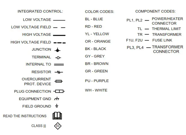
Wiring Diagram
![]() WARNING
WARNING![]() HIGH VOLTAGE!
HIGH VOLTAGE!
DISCONNECT ALL POWER BEFORE SERVICING OR INSTALLING THIS UNIT. MULTIPLE POWER SOURCES MAY BE PRESENT. FAILURE TO DO SO MAY CAUSE PROPERTY DAMAGE, PERSONAL INJURY OR DEATH.
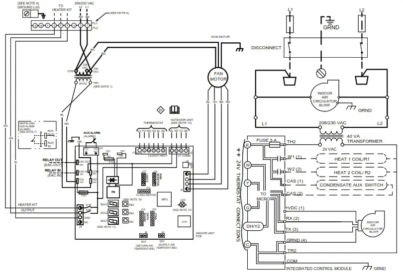
NOTES:
- PLACE RED WIRE ON 208 V TERMINAL OF TRANSFORMER (TR1) FOR 208 VAC OPERATION.
- MANUFACTURER’S SPECIFIED REPLACEMENT PARTS MUST BE USED WHEN SERVICING.
- IF ANY OF THE ORIGINAL WIRES AS SUPPLIED WITH THIS UNIT MUST BE REPLACED, IT MUST BE REPLACED WITH WIRING MATERIAL HAVING A TEMPERATURE RATING OF AT LEAST 105°C. USE COPPER CONDUCTORS ONLY.
- UNIT MUST BE PERMANENTLY GROUNDED AND CONFORM TO N.E.C AND LOCAL CODES.
- DISCARD CONNECTOR PL1 WHEN INSTALLING OPTIONAL HEAT KIT.
- REMOVE JUMPER TAB AND PUT AUX ALARM SWITCH WHEN INSTALLING AUX ALARM SWITCH.
- USE N.E.C CLASS 2 WIRE.
- SEE MANUAL FOR PUSH BUTTON OPERATION.
- SEE MANUAL FOR 7-SEGMENT DISPLAY DIAGNOSTIC CODES AND MENU CODES
- SEE MANUAL FOR LED FUNCTIONALITY.
- RAND C TERMINALS (USED FOR 24VAC OUTDOOR CONTROL VOLTAGE) ARE OPTIONAL FOR 2 STAGE COMMUNICATING AIR CONDITIONERS. R AND C TERMINALS ARE NOT TO BE USED FOR 2 STAGE COMMUNICATING HEAT PUMP APPLICATIONS.
FOR COMMUNICATING HEAT PUMPS OR IF ONLY TWO THERMOSTAT WIRES ARE AVAILABLE, A SEPARATE TRANSFORMER MUST BE INSTALLED IN THE OUTDOOR UNIT FOR CONTROL BOARD POWER. 1 AND 2 WIRES ARE REQUIRED FOR ALL APPLICATIONS. SEE INSTALLATION MANUAL FOR FULL SYSTEM WIRING EXAMPLES.
Wiring is subject to change. Always refer to the wiring diagram on the unit for the most up-to-date wiring.
NOTE:
WHEN INSTALLING HEATER KIT, ENSURE SPEED TAP MUST EXCEED OR EQUAL THE MINIMUM BLOWER SPEED (MBS) SPECIFIED FOR THE AIRHANDLERIHEATER KIT COMBINATION ON THIS UNIT’S SERIAL PLATE. AFTER INSTALLING OPTIONAL HEATER KIT, MARK AN “r IN THE BOX ON THE SERIAL PLATE CORRESPONDING TO THE HEATER KIT USED. NO MARK INDICATES NO HEATER KIT INSTALLED.
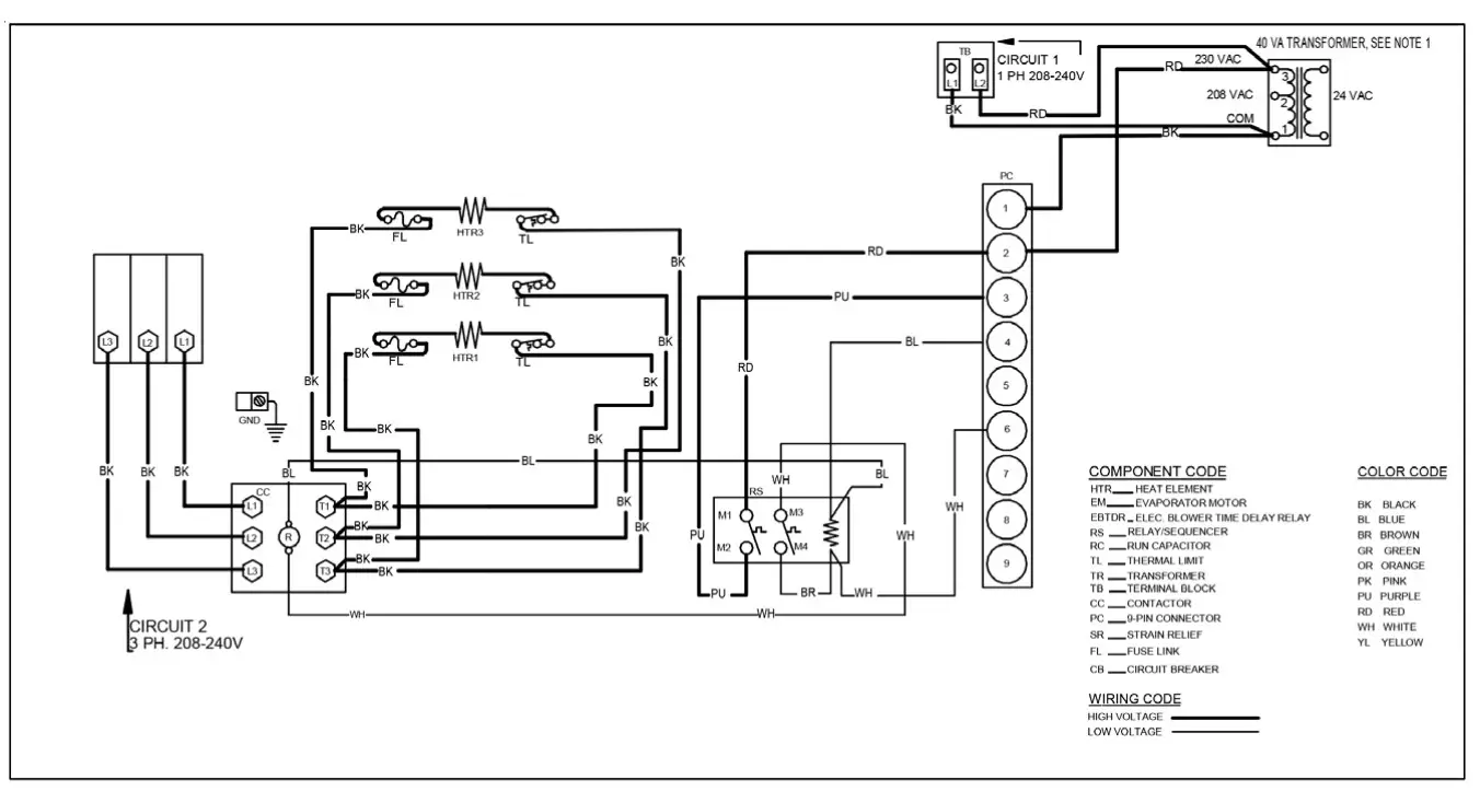
NOTE:-THIS LABEL MUST BE ATTACHED ON THE AIRHANDLER IN A PROMINENT LOCATION
AIR HANDLER
AIR HANDLER HOMEOWNER’S ROUTINE MAINTENANCE RECOMMENDATIONS
Replace or Clean Filter
IMPORTANT NOTE: Never operate unit without a filter installed as dust and lint will build up on internal parts resulting in loss of efficiency, equipment damage and possible fire.
An indoor air filter must be used with your comfort system.
A properly maintained filter will keep the indoor coil of your comfort system clean. A dirty coil could cause poor operation and/or severe equipment damage.
Your air filter or filters could be located in your furnace, in a blower unit, or in “filter grilles” in your ceiling or walls. The installer of your air conditioner or heat pump can tell you where your filter(s) are, and how to clean or replace them.
Check your filter(s) at least once a month. When they are dirty, replace or clean as required. Disposable type filters should be replaced. Reusable type filters may be cleaned.
You may want to ask your dealer about high efficiency filters. High efficiency filters are available in both electronic and non-electronic types. These filters can do a better job of catching small airborne particles.
Motors
Indoor and outdoor fan motors are permanently lubricated and do not require additional oiling.
WARNING
HIGH VOLTAGE![]() DISCONNECT ALL POWER BEFORE SERVICING OR INSTALLING THIS UNIT. MULTIPLE POWER SOURCES MAY BE PRESENT. FAILURE TO DO SO MAY CAUSE PROPERTY DAMAGE, PERSONAL INJURY OR DEATH.
DISCONNECT ALL POWER BEFORE SERVICING OR INSTALLING THIS UNIT. MULTIPLE POWER SOURCES MAY BE PRESENT. FAILURE TO DO SO MAY CAUSE PROPERTY DAMAGE, PERSONAL INJURY OR DEATH.
ALUMINUM INDOOR COIL CLEANING
(QUALIFIED SERVICER ONLY) This unit is equipped with an aluminum tube evaporator coil. The safest way to clean the evaporator coil is to simply flush the coil with water. This cleaning practice remains as the recommended cleaning method for both copper tube and aluminum tube residential evaporator coils.
It has been determined that many coil cleaners and drain pan tablets contain corrosive chemicals that can be harmful to aluminum tube and fin evaporator coils. Even a onetime application of these corrosive chemicals can cause premature aluminum evaporator coil failure. Any cleaners that contain corrosive chemicals including, but not limited to, chlorine and hydroxides, should not be used. An alternate cleaning method is to use one of the products listed in TP-109* to clean the coils. The cleaners listed are the only agents deemed safe and approved for use to clean round tube aluminum coils. TP-109 is also available on the web site in Partner Link > Service Toolkit.
NOTE: Ensure coils are rinsed well after use of any chemical cleaners.
CAUTION
TO AVOID THE RISK OF EQUIPMENT DAMAGE OR FIRE, INSTALL THE SAME AMPERAGE BREAKER OR FUSE AS YOU ARE REPLACING. IF THE CIRCUIT BREAKER OR DUSE SHOULD OPEN AGAIN WITHIN THIRTY DAYS, CONTACT A QUALIFIED SERVICER TO CORRECT THE PROBLEM.
IF YOU REPEATEDLY RESET THE BREAKER OR REPLACE THE FUSE WITHOUT HAVING THE PROBLEM CORRECTED, YOU RUN THE RISK OF SEVERE EQUIPMENT DAMAGE.
BEFORE YOU CALL YOUR SERVICER
- Check the thermostat to confirm that it is properly set.
- Wait 15 minutes. Some devices in the outdoor unit or in programmable thermostats will prevent compressor operation for awhile, and then reset automatically. Also, some power companies will install devices which shut off air conditioners for several minutes on hot days. If you wait several minutes, the unit may begin operation on its own.
- Check the electrical panel for tripped circuit breakers or failed fuses. Reset the circuit breakers or replace fuses as necessary.
- Check the disconnect switch near the indoor furnace or blower to confirm that it is closed.
- Check for obstructions on the outdoor unit. Confirm that it has not been covered on the sides or the top. Remove any obstruction that can be safely removed. If the unit is covered with dirt or debris, call a qualified servicer to clean it.
- Check for blockage of the indoor air inlets and outlets. Confirm that they are open and have not been blocked by objects (rugs, curtains or furniture).
- Check the filter. If it is dirty, clean or replace it.
- Listen for any unusual noise(s), other than normal operating noise, that might be coming from the outdoor unit. If you hear unusual noise(s) coming from the unit, call a qualified servicer.
Start-Up Checklist
Air Handler / Coil
Model Number…………………………..
Serial Number…………………………….
ELECTRICAL
| Line Voltage (Measure L1 and L2 Voltage) | L1 – L2 |
| Secondary Voltage (Measure Transformer Output Voltage) | R – C |
| Blower Amps | |
| Heat Strip 1 – Amps | |
| Heat Strip 2 – Amps |
BLOWER EXTERNAL STATIC PRESSURE
| Return Air Static Pressure | IN. W.C. |
| Supply Air Static Pressure | IN. W.C. |
| Total External Static Pressure (Ignoring +/- from the reading above, add total here) | IN. W.C. |
TEMPERATURES
| Return Air Temperature (Dry bulb / Wet bulb) | DB °F………….WB °F |
| Cooling Supply Air Temperature (Dry bulb / Wet bulb) | DB °F……………WB °F |
| Heating Supply Air Temperature | DB °F |
| Temperature Rise | DB °F |
| Delta T (Difference between Supply and Return Temperatures) | DB °F |
Air Handler / Coil – (Inverter Matched)
INVERTER AH / COIL ONLY
Check EEV and EEV wiring is secure (no adjustment required)
| Check wire routings for any rubbing | |
| Check product for proper draining | |
| Check screw tightness on blower wheel | |
| Check factory wiring and wire connections | |
| Check product for proper clearances as noted by Installtion instructions |
°F to °C formula: (°F – 32) divided by 1.8 = °C °C to °F formula: (°C multiplied by 1.8) + 32 = °F
CUSTOMER FEEDBACK
We are very interested in all product comments.
Please fill out the feedback form on one of the following links:
Goodman® Brand Products: (http://www.goodmanmfg.com/about/contact-us).
Amana® Brand Products: (http://www.amana-hac.com/about-us/contact-us).
You can also scan the QR code on the right for the product brand you purchased to be directed to the feedback page.
 |  |
| https://www.goodmanmfg.com/about/contact-us | http://www.amana-hac.com/about-us/contact-us |
PRODUCT REGISTRATION
Thank you for your recent purchase. Though not required to get the protection of the standard warranty, registering your product is a relatively short process, and entitles you to additional warranty protection, except that failure by California and Quebec residents to register their product does not diminish their warranty rights. The duration of warranty coverages in Texas differs in some cases. For Product Registration, please register as follows:
Goodman® Brand products: (https://www.goodmanmfg.com/product-registration).
Amana® Brand products: (http://www.amana-hac.com/product-registration).
You can also scan the QR code on the right for the product brand you purchased to be directed to the Product Registration page.
 |  |
| https://www.goodmanmfg.com/product-registration | http://www.amana-hac.com/product-registration |
![]() Our continuing commitment to quality products may mean a change in specifications without notice.
Our continuing commitment to quality products may mean a change in specifications without notice.
19001 Kermier Road Waller, TX 77484
www.goodmanmfg.com
www.amana-hac.com
© 2022-2023 Daikin Comfort Technologies Manufacturing, L.P.
is a registered trademark of Maytag Corporation or its related companies and is used under license.
All rights reserved.  IOG-4040B~IOG-4040B~022023~8
References
 Quality, Durable Heating & Air Conditioning Systems From Amana
-
Contact Amana Heating & Air Conditioning
-
Register Your Amana Heating And Cooling Equipment Here
-
Air Conditioning and Heating Systems| HVAC | Goodman
-
Contact Us | Goodman Manufacturing
-
Silicon Labs
-
Warranty Registration | Register Your Goodman HVAC Product


