
![]() Panel on Zigbee
Panel on Zigbee
Instruction Manual
Important: Read All Instructions Prior to Installation
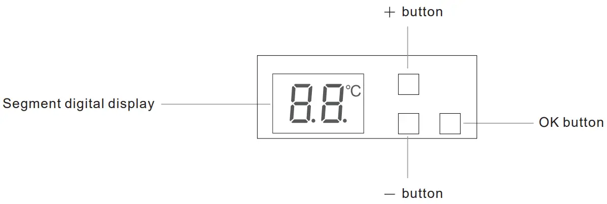
Function introduction
Safety & Warnings
- DO NOT install with power applied to
- DO NOT expose the device to
Product Data
| Radio Frequency | 2.4GHz |
| Operation Mode | OFF, MANUAL, AUTO |
| Measurement range | 0°C to +60°C |
| Set Temperature Range | 5°C to 35°C |
| Hysteresis | 0.5°C to 2°C |
| Ambient Temperature | 0°C to 40°C (during operation) |
- The Zigbee heating panel is a wireless heating device, which complies with Zigbee 0 wireless protocol standards. The thermostat has 3 operation modes which can be controlled manually and locally or remotely controlled through the Zigbee gateway controller.
- All setup is performed via supported IEEE 15.4-based control platforms and other Zigbee3.0 compatible control systems.
- Operation Modes: OFF, MANUAL, AUTO
- Measurement range: 0°C to +60°C
- WARNING: Electrical power must be switched off during installation
Basic Function Introduction
2.1 Switch Operation modes
Short press the “OK” button to switch operation modes.
Manual: ![]() (”MA”), the temperature can be set by APP and manually. After switching from another mode to this mode, the
(”MA”), the temperature can be set by APP and manually. After switching from another mode to this mode, the![]() icon will flash slowly for 5 seconds then the display will show the set temperature.
icon will flash slowly for 5 seconds then the display will show the set temperature.
Auto: ![]() (”AU”), only when the device is added to a Zigbee network, the temperature of a time period can be set through APP. After switching from another mode to this mode, the
(”AU”), only when the device is added to a Zigbee network, the temperature of a time period can be set through APP. After switching from another mode to this mode, the![]() icon will flash slowly for 5 seconds then the display will show the set temperature.
icon will flash slowly for 5 seconds then the display will show the set temperature.
The sequence of operation modes is as follows: Manual, Auto.
2.2 Modify Set Temperature
Under Manual modes, short press or hold the button “+”, and “-” to modify the set temperature. The temperature can also be configured through the corresponding at the tribute of the Thermostat Cluster (0x0201).
Under Auto mode, the temperature can only be configured through the command SetWeeklySchedule of Thermostat Cluster (0x0201). Please refer to the chapter Thermostat-0x0201(Server) for detailed information.
2.3 Weekly Schedule
The weekly schedule will be executed under the Auto mode, and it can not be modified through buttons, it can only be configured through the command SetWeeklySchedule, the default configuration is as follows:
Monday-Friday: 7:30 30℃,12:00 25℃,18:00 28℃,22:00 20℃
Saturday-Sunday: 7:30 35℃,12:00 30℃,18:00 25℃,22:00 29℃
2.4 Adding to a Zigbee Network or Removed from a Zigbee Network
Adding to a Zigbee Network: make sure the device has not been added to any Zigbee network, hold the “OK” button for over 5 seconds, and the device will enter network pairing mode and search the nearby networks for 3 minutes, and the network icon![]() flashes slowly, once added to a network successfully, the network
flashes slowly, once added to a network successfully, the network![]() icon will turn on for 3 seconds (OFF status) or stay solid on (non-OFF status), or reset the power of the device, it will enter network pairing mode automatically and search nearby network.
icon will turn on for 3 seconds (OFF status) or stay solid on (non-OFF status), or reset the power of the device, it will enter network pairing mode automatically and search nearby network.
Removed from a Zigbee Network: hold the “OK” button for over 5 seconds, and the device will be removed from the Zigbee network, and the configuration parameters will not be cleared.
Factory Reset: hold the three buttons “OK”, “+”, “-” simultaneously for over 5 seconds, the display will show![]() (”rE”) flashing 3 times, then the temperature will be restored to 19℃, which means the device has been reset to factory default successfully and removed from the Zigbee network, and the configuration parameters will be cleared.
(”rE”) flashing 3 times, then the temperature will be restored to 19℃, which means the device has been reset to factory default successfully and removed from the Zigbee network, and the configuration parameters will be cleared.
2.5 Display Auto Off
When Display Auto Off mode is activated, the display will go off status if there is no operation within 30 seconds.
When the Display Auto Off function is not activated, hold the two buttons “OK”, and “-” simultaneously for over 5 seconds until all icons on the display flash 3 times slowly, and the Display Auto Off mode will be activated. When the Display Auto Off function is activated, hold the two buttons “OK”, and “-” simultaneously for over 5 seconds, during the process, all icons on the display flash slowly, and until all icons on the display go off, the Display Auto Off mode will be deactivated.
The Display Auto Off mode can also be configured through the proprietary attribute DisplayAutoOffActivate (0x1001) of Thermostat Cluster (0x0201).
2.6 Self-Check Function Test
Reset the power of the device, within 10 seconds, press and hold both “OK” and “-” buttons simultaneously for 4 seconds, and the “H” cursor will turn on and stay solid on, which means the device has entered the self-check function test.
| Short press the “+” button | Manual switching on-off TRIAC |
| Short press “-” button | Display the sensing room temperature of the temperature sensor head, when the sensing room temperature is over 50°C, the display will show 50°C, when the sensing room temperature is lower than 0°C (including the situation that the temperature sensor head falls off or short circuit), the display will show error indication: E1 and the display will show the real sensing temperature under other situations. |
| Short press the “OK” button | Check whether the device has a memory function: the display will show 11. |
2.7 Hysteresis (0.5°C by default)
To prevent the undulation of sensor temperature when the sensor temperature is approaching the set temperature, which will cause the controller may keep switching on/off the TRIAC. Here hysteresis enables the controller to control the TRIAC only when the value tolerance between the sensor temperature and the set temperature within a set range, this value can be set.
For instance, when the set temperature is 20°C, and hysteresis is set at 0.5 °C, the following figure shows how the TRIAC works.
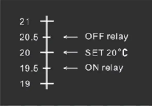
This value can also be configured through the proprietary attribute Hysterersis (0x100A) of Thermostat Cluster (0x0201).
2.8 Window Open Detect (Off by default)
On normal operation interface, hold both “+” and “OK” buttons simultaneously for 5 seconds to enter Window Open Detect setting, ![]() icon flashes, the digital display will show
icon flashes, the digital display will show![]() (”ON”) or
(”ON”) or![]() (”OF”), short press “+” or “-” button to select “ON” or “OF”. If “ON” is selected, the Window Open Detect mode will be activated. If “OF” is selected, the Window Open Detect mode will be deactivated. After the setting is completed, if there is no operation within 5 seconds or short press the “OK” button directly, the setting will be saved and the display will return to the normal operation interface. By factory default, the Window Open Detect mode is off, the user needs to activate it by himself. This function can also be configured through the proprietary attribute WindowOpenCheck (0x1009) of Thermostat Cluster (0x0201).
(”OF”), short press “+” or “-” button to select “ON” or “OF”. If “ON” is selected, the Window Open Detect mode will be activated. If “OF” is selected, the Window Open Detect mode will be deactivated. After the setting is completed, if there is no operation within 5 seconds or short press the “OK” button directly, the setting will be saved and the display will return to the normal operation interface. By factory default, the Window Open Detect mode is off, the user needs to activate it by himself. This function can also be configured through the proprietary attribute WindowOpenCheck (0x1009) of Thermostat Cluster (0x0201).
When Window Open Detect mode is activated, the![]() icon will stay solid on.
icon will stay solid on.
Once the device is powered on and working stable if the temperature decreases to 5°C within 10 minutes, the window open mark will be enabled, and the proprietary attribute Window Open flag (0x100B) of Thermostat Cluster (0x0201) will be set to value 1 (Window is opened), the set temperature will be switch to 7°C, then the icon![]() will flash slowly. After the window open mark is enabled, if the temperature increases by 2°C, or if the power of the device is reset, or short press any button, the proprietary attribute Window Open flag (0x100B) of Thermostat Cluster (0x0201) will be reset, then the device will return to the previous operation mode. Note: the device will collect the Window Open Detect temperature, this function will work better when the device is installed beside the window or door.
will flash slowly. After the window open mark is enabled, if the temperature increases by 2°C, or if the power of the device is reset, or short press any button, the proprietary attribute Window Open flag (0x100B) of Thermostat Cluster (0x0201) will be reset, then the device will return to the previous operation mode. Note: the device will collect the Window Open Detect temperature, this function will work better when the device is installed beside the window or door.
2.9 Temp Compensation
The displayed temperature may have big tolerance caused by the sensor or other factors, so it is necessary to do temp compensation with the temperature sensor.
This value can also be configured through the attribute LocalTemperatureCalibration (0x0010) of Thermostat Cluster (0x0201).
2.10 RePower status
Device state after reset power of the device.
If set as “last status”, the device will go to the status before power failure after power on again.
If set as “default”, the device will go to default mode after powering on again.
This status can also be configured through the proprietary attribute PowerUpStatus (0x1004) of Thermostat Cluster (0x0201).
2.11 Operate Brightness
The segment digital displays brightness when operating the device.
This brightness can also be configured through the proprietary attribute OperateDisplayBrightness (0x1000) of Thermostat Cluster (0x0201).
2.12 Child Lock
The Child Lock can be activated or deactivated by holding the two buttons “+”, and “-” simultaneously on the normal operation interface.
When the Child Lock function is not activated, hold the “+” and “-” buttons simultaneously for over 5 seconds, until![]() (“CC”) flashes slowly, release the buttons, then the Child Lock function is activated. Once the Child Lock function is activated, short press any button,
(“CC”) flashes slowly, release the buttons, then the Child Lock function is activated. Once the Child Lock function is activated, short press any button,![]() (”CC”) will flash 3 times slowly.
(”CC”) will flash 3 times slowly.
When the Child Lock function is activated, hold the “+” and “-” buttons simultaneously for over 5 seconds, during the process,![]() (“CC”) flashes slowly, until
(“CC”) flashes slowly, until![]() (”CC”) goes off, then the Child Lock function is deactivated. Once the Child Lock function is activated, short press any button,
(”CC”) goes off, then the Child Lock function is deactivated. Once the Child Lock function is activated, short press any button,![]() (”CC”) will flash 3 times slowly.
(”CC”) will flash 3 times slowly.
The Child Lock can also be configured through the attribute KeypadLockout of Thermostat User Interface Configuration – 0x0204.
2.13 Internal Over Heat Protection
A: If the PCB temperature is over a temperature between 85°C-90°C after the device software has been forced to work for 30 seconds, the device will work normally for another 30 seconds, then it will be forced to stop working for 40 seconds, and the device status will alternate between working normally for 30 seconds and stop working for 40 seconds, and the alternating will cycle and last for around 10 minutes, then the software will evaluate again.
B: If the PCB temperature is over 90°C during operation, the device will stop heating, after the PCB temperature is lower than 85°C, the software will evaluate again. The Over Heat mark can also be configured through the proprietary attribute (0x2002) of the Thermostat Cluster (0x0201).
2.14 Over Load Alarm Function
If the overload is detected, the device will turn off the TRIAC output, different versions with different overload thresholds:
1000W version: overload threshold is 1500W
800W version: overload threshold is 1200W
600W version: overload threshold is 900W
400W version: overload threshold is 600W
If an alarm occurs, the output will be turned off, the display shows slow flashing of ![]() (“AL”), and the alarm can be canceled by holding the OK button for over 5 seconds or by Zigbee gateway. To configure whether to enable or disable Over Load Alarm, please refer to the parts Alarm-0x0009 and Electrical Measurement-Ox0b04.
(“AL”), and the alarm can be canceled by holding the OK button for over 5 seconds or by Zigbee gateway. To configure whether to enable or disable Over Load Alarm, please refer to the parts Alarm-0x0009 and Electrical Measurement-Ox0b04.
2.15 Compensation for the Set Temperature
| Set Temperature Value (°C) | Under 10 | 10-21 | 22-25 | 26-29 | 30-35 |
| Real Set Temperature Value (°C) | Original value | Original value+3 | Original value+5 | Original value+7 | Original value+8 |
Zigbee Interface
3.2 Application Endpoint #1 –Thermostat
Cluster | supported | Description |
| 0x0000 | server | Basic Provides basic information about the device, such as the manufacturer ID, vendor and model name, stack profile, ZCL version, production date, hardware revision, etc. Allows a factory reset of attributes, without the device leaving the network. |
| 0x0003 | server | Identify Allows putting the endpoint into identify mode. Useful for identifying/locating devices and required for Finding & Binding. |
| 0x0004 | server | Groups Allows adding this endpoint to one or more groups. Afterward, the endpoint can be addressed using the group address. This is also a prerequisite for scenes. You may also query group membership and delete group associations. |
| 0x0005 | server | Scenes Allows storing one or more scenes per group, where each scene consists of a pre-set on/off state value. You may either store the current values as a scene, provide scene settings when adding a scene or delete scenes. |
| 0x0201 | server | Thermostat |
| 0x0702 | server | Simple Meter |
| 0x0b04 | server | Electrical Measurement Measure power, voltage, current |
| 0x0009 | server | Alarm Device related alarm |
| 0x0019 | Client | OTA Upgrade Pull-oriented firmware upgrade. Searches the network for mating servers and allows the server to control all stages of the upgrade process, including which image to download, when to download, at what rate, and when to install the downloaded image. |
| 0x000a | Server | Time |
| 0x0204 | Server | Thermostat User Interface Configuration |
3.2.1 Basic -0x0000 (Server)
Attributes supported:
Attribute | Type | Description |
| 0x0000 | INT8U, read-only | ZCL Version 0x03 |
| 0x0001 | INT8U, read-only | Application version This is the firmware version number of the application |
| 0x0002 | INT8U, read-only | Stack Version |
| 0x0003 | INT8U, read-only | HW Version Hardware version 1 |
| 0x0004 | string, read-only | Manufacturer Name “NAMRON AS” |
| 0x0005 | string, read-only | ModelIdentifier “5401392 & 5401396”/“5401393 & 5401397”/“5401394 & 5401398”/“5401395 & 5401399” |
| 0x0006 | string, read-only | Date Code NULL |
| 0x0007 | ENUM8, read-only | Power Source Device power supply, fixed value 0x01 Mains (single phase) |
| 0x0008 | ENUM8, read-only | Generic Device-Class 0XFF |
| 0x0009 | ENUM8, read-only | GenericDevice-Type 0XFF |
| 0x000A | oct read-only | ProductCode 00 |
| 0x000B | string, read-only | ProductURL NULL |
| 0x4000 | string, read-only | Sw build id 6.9.1.0_r4 |
Command supported:
Command | Description |
| 0x00 | Reset to Factory Defaults Command On receipt of this command, the device resets all the attributes of all its clusters to their factory defaults. Note that networking functionality, bindings, groups, or other persistent data are not affected by this command. |
3.2.2 Scenes 0x0005 (Server)
Attributes supported:
Attribute | Type | Description |
| 0x0000 | int8u, read-only | Scene Count Holds the total number of scenes (across all groups) currently stored on the device. |
| 0x0001 | int8u, read-only | Current Scene If the SceneValid attribute is true, this attribute, together with the CurrentGroup attribute, indicates the currently active scene. |
| 0x0002 | int16u, read-only | Current Group If the SceneValid attribute is true, this attribute, together with the CurrentScene attribute, indicates the currently active scene. |
| 0x0003 | bool, read-only | Scene Valid If true, the scene identified by CurrentGroup and CurrentScene is currently active, i.e. all device attribute values match the values in the scene fieldset. |
| 0x0004 | bitmap8, read-only | Name Support |
Command supported:
Command | Description |
| 0x00 | Add Scene Adds a scene with or without a scene field set |
| 0x01 | View Scene Returns the scene fieldset, name, and transition times for a scene. |
| 0x02 | Remove Scene Removes a scene from the scene table. |
| 0x03 | Remove All Scenes Removes all scenes that belong to a particular group. |
| 0x04 | Store Scene Stores the device’s current state as a scene or updates a previously stored scene accordingly |
| 0x05 | Recall Scene Reverts the device’s current state using the values from the previously stored fieldset. |
3.2.3 Groups-0x0004 (Server)
Attributes supported:
Attribute | Type | Description |
| 0x0000 | bitmap8, read-only | NameSupport 0, not supported |
Command supported:
Command | Description |
| 0x00 | Add Group Adds the endpoint to a group. |
| 0x01 | View Group Determines whether the device belongs to a group and returns the group name if supported |
| 0x02 | Get Group Membership Returns the set of groups this endpoint belongs to |
| 0x03 | Remove Group Removes this endpoint from the specified group. Also removes all scenes that refer to this group. |
| 0x04 | Remove All Groups Removes this endpoint from all groups. Also removes all scenes that refer to any of the existing groups. |
| 0x05 | Add Group if Identifying Adds this endpoint to the group, if the endpoint is identified. |
3.2.4 Thermostat-0x0201(Server)
Attributes supported:
Attribute | Type | Description |
| 0x0000 | int16S, read-only, reportable | Local Temperature Attribute This is room temperature, the maximum resolution this format allows is 0.01 ºC. |
| 0x0010 | Int8S, reportable | Local Temperature Calibration The room temperature calibration, the range is -30-30, the maximum resolution this format allows 0.1°C. Default value: 0 |
| 0x0011 | int16S, reportable | Occupied Cooling Setpoint This system is not invalid. |
| 0x0012 | int16S, reportable | Occupied Heating Setpoint The range is 500-3500, and the maximum resolution this format allows is 0.01 ºC. Default is 0xbb8(30.00ºC) Note: only Dry mode and Manual mode can be set through this attribute. |
| 0x001B | Enum8, reportable | Control Sequence Of Operation Set device supported operation type, here only supports Heating Only(0x02) |
| 0x001C | Enum8, reportable | System Mode System operation mode, supports 0x00(off) 0x04(heat) |
| 0x0029 | Map16, read-only, reportable | HVAC relay state/ Thermostat Running State Indicates the relay on/off status, here only supports bit0( Heat State) |
| 0x0020 | Enum8, reportable | Start Of Week |
| 0x0021 | Int8u, read-only, reportable | Number Of Weekly Transitions Fixed 7, 7 transitions |
| 0x0022 | Int8u, read-only, reportable | Number Of Daily Transitions Fixed 4, 4 time periods |
Proprietary Attributes:
Attribute | Type | Manufacturer code | Description |
| 0x1000 | ENUM8, reportable | 0x1224 | Operate Display Brightness Segment digital display brightness: Value: 1~7, default brightness is 1 |
| 0x1001 | ENUM8 reportable | 0x1224 | Display Auto Off Activation 0, deactivated (default) 1, activated |
| 0x1004 | ENUM8 reportable | 0x1224 | Power Up Status The mode after resetting the power of the device: Value=0: manual mode after power up, set temperature 19ºC | Value=1: last status before power off (Default) |
| 0x1009 | ENUM8 reportable | 0x1224 | Window Open Check 0: enable 1: disable |
| 0x100A | INT8U reportable | 0x1224 | Hysteresis Hysteresis setting, the range is 5-50, the unit is 0.1ºC, and the default value is 5 |
| 0x100B | ENUM8, Reportable Read only | 0x1224 | Window Open flag 0: Window is not opened 1: Window is opened |
| 0x2002 | ENUM8, Reportable Read only | 0x1224 | Internal Over Heat Mark 0: no 1: temperature over 85ºC and lower than 90ºC 2: temperature over 90ºC |
Command supported:
Command | Description |
| 0x0000 | Setpoint Raise/Lower Increase or decrease the set temperature according to the current mode, the unit is 0.1ºC Note: only Dry mode and Manual mode can be configured through this attribute. |
| 0x0001 | Set Weekly Schedule The time period setting is under Auto mode. The number of Transitions for the Sequence must be 4, which means 4-time points should be set. Mode for Sequence, it must be 1, which means only heat supported. The set time points, the latter one must be later than the previous one. If a schedule of someday is configured, previous schedules will be covered. Note: the set value of the schedule configured by this command will be executed under Auto mode. |
| 0x0002 | Get Weekly Schedule |
3.2.5 Simple Meter-0x0702 (Server)
Attributes supported:
Attribute | Type | Description |
| 0x0000 | unsigned48, read-only, reportable | Current Summation Delivered Indicates the current amount of electrical energy delivered to the load. |
| 0x0200 | bitmap8, read-only | Status Flags indicating current device status always is 0x00 |
| 0x0300 | enum8, read-only | Unit Of Measure Unit of metering data, this is always kWh(0x00) |
| 0x0301 | Int24U, read-only | Multiplier |
| 0x0303 | map8, read-only | Summation Formatting” The decimal point at both left and right sides of the data, is always 0x19 |
| 0x0306 | bitmap8, read-only | Metering Device Type The metering data type is always Electric Metering (0x00) |
| 0x0302 | Int24U, read-only | Divisor |
3.2.6 Electrical Measurement-0x0b04(Server)
Attributes supported:
Attribute | Type | Description |
| 0x0000 | bitmap32, read-only | Measurement Type Indicates the physical entities that this device is able to measure. Supports only bit0: Active measurement (AC) |
| 0x0505 | bitmap8, read-only | RMS Voltage Valid voltage of single phase, unit is V |
| 0x0508 | int16U, reportable, read-only | recurrent The valid current of a single phase, unit is A |
| 0x050B | int16S, reportable read-only | Active Power Valid power of single phase, unit is W |
| 0x0600 | int16U, read-only | AC Voltage Multiplier 0x01 |
| 0x0601 | int16U, read-only | AC Voltage Divisor 0x0a used together with above attribute, real displayed voltage= RMSVoltage* ACVoltageMultiplier/ACVoltageDivisor |
| 0x0602 | int16U, read-only | AC Current Multiplier 0x01 |
| 0x0603 | int16U, read-only | AC Current Divisor 0x3e8 (1000) used together with above attribute, real displayed current=RMSCurrent*ACCurrentMultiplier/ACCurrentDivisor |
| 0x0604 | int16U, read-only | AC Power Multiplier 0x01 |
| 0x0605 | int16U, read-only | ACPowerDivisor 0x0a (10) used together with the above attribute, real displayed power=ActivePower * AC power Multiplier/ACPower Divisor |
| 0x0800 | int16U, | ACAlarmsMask Specifies which configurable alarms may be generated, only Bit2: Active Power Overload whether to enable overload alarm or not |
| 0x0803 | int16U, reportable, read-only | ACActivePowerOverload Alarms when the load value is over a certain value, for the unit please refer to ActivePower |
3.2.7 Alarm-0x0009(Server)
Please set the valid value of attribute ACAlarmsMask of Electrical Measurement, the Alarm Server cluster can generate the following commands:
Camden | Description |
| 0x00 | Alarm Alarm code: Identifying code for the cause of the alarm, as given in the specification of the cluster whose attribute generated this alarm. |
The overload alarm is according to ACAlarmsMask, the alarm code is 2. If the alarm is not canceled, it will be reported every 1 minute.
The Alarm Server cluster can receive the following commands:
3.2.8 Time-0x000A(server)
The Time cluster is a general cluster for the time it is based on a UTC time in seconds since 0 hrs 0 mins 0 sec on 1st January 2000. Refer to [Z2] for the ZigBee specification of the time cluster.
The metering device will use these clusters as a server– provided that a suitable Time Server is available on the network (most likely on the Gateway/concentrator)
Attributes supported:
Attribute | Type | Description |
| 0x0000 | UTC | Time |
| 0x0001 | MAP8 | Time Status 0x02 bit0:0, not master clock Bit1:1, Synchronized |
3.2.9 OTA Upgrade-0x0019(Client)
OTA complies with standard Zigbee protocol.
3.2.10 Thermostat User Interface Configuration-0x0204(Server)
Attributes supported:
Attribute | Type | Description |
| 0x0000 | ENUM8, reportable | TemperatureDisplayMode 0x00 Temperature in °C only support |
| 0x0001 | ENUM8, reportable | Keypad Lockout 0x00 No lockout 0x01 – 0x05 lockout |
3.3 Application Endpoint #242 GreenPower
![]() Namron AS
Namron AS
Nedre kalbakkvei 88B
1081 Oslo
Norway
[email protected]


