![]() AC301
AC301
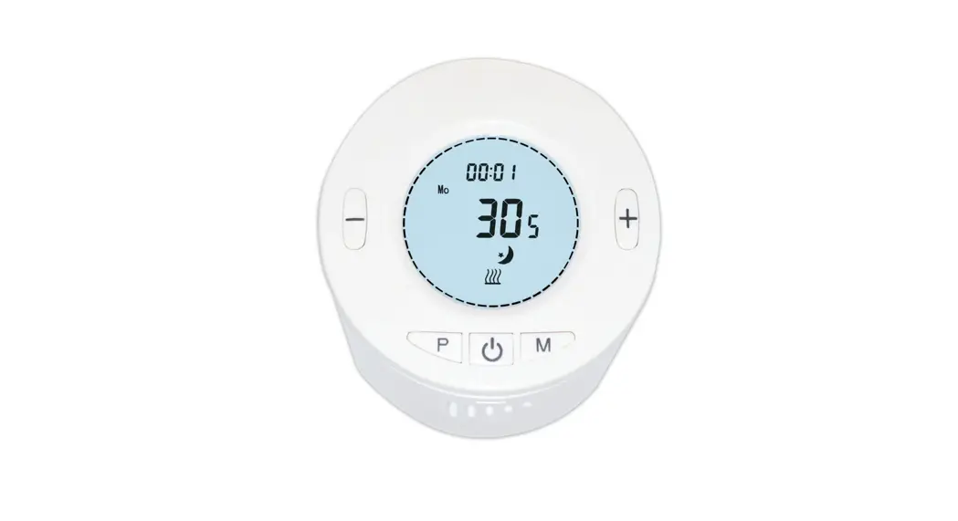
Thermostatic Radiator Valve
Thermostatic Radiator Valves (TRVs) sense the air temperature around them and regulate the flow of water through the radiator to which they are fitted. They can be set at a level that gives you the room temperature you want. These settings may have to be different in each room, and you can set the TRVs to suit each room and then leave them to do their job. The device can be set temperature by manual or by gateway and schedules are created by gateway. This product can be operated in any Z-Wave network with other Z-Wave certified devices from other manufacturers. All mains operated nodes within the network will act as repeaters regardless of vendor to increase the reliability of the network.
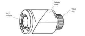
Product Overview
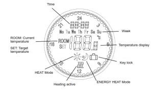
LCD Display
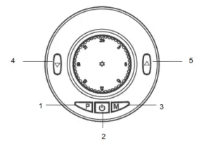
| Button name | Function | |
| 1. | P button | For RF inclusion |
| 2. | Power on/off | Turn on/off TRV |
| 3. | M button | Mode select: HEAT/ ENERGY HEAT |
| 4. | Down button | Reduce Target Temperature |
| 5. | Up button | Increase Target Temperature |
Installation
Mounting
Do not insert the batteries yet.
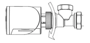
- Remove any existing control from the radiator valve
- Mount the TRV on the valve and tighten it by turning the Valve cap clockwise.

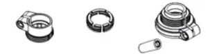
- You may need to use one of the adaptors supplied to fit your radiator valve:
4. The TRV can be mounted at various orientations as shown below:
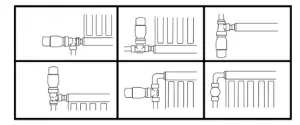
Note: The TRV needs a free flow of air to sense the temperature so they must not be covered by curtains or blocked by furniture
Calibration
- The unit supports the SmartStart function, SmartStart enabled products can be added into a Z-Wave network by scanning the Z-Wave QR Code present on the product with a controller providing SmartStart inclusion. No further action is required and the SmartStart product will be added automatically within 10 minutes of being switched on in the network vicinity.
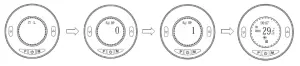
- After finishing inclusion, the unit will start initializing itself. During this period the LCD will display INIL with backlight flashing for 2 minutes.
- When the TRV displays ADAP, press the UP button to start the calibration. The number 0 will change to number 1. If it does not change to 1, press the UP button again.
- The TRV will start to adapt itself to the stroke of the valve’s body by opening and closing the valve twice to store the endpoints. This could take up to 1 minute.

- Calibration is complete when temperature readings appear on the LCD.
Note: Temperature readings will become accurate 10 minutes after installing the batteries.
Operation
- The user can choose between two heat levels for automatic temperature control without user intervention. This can be selected either by button M or set through the gateway.
“HEAT” mode: This is a higher temperature level for indoor comfort and is normally used when a room is occupied.
“ENERGY HEAT” mode: This is the lower temperature level for energy saving, typically used during sleeping or when a room is empty. Setpoints for these two modes must first be preset through the gateway. The TRV will activate heating whenever room temperature falls below these setpoints. - Users can use the gateway’s scheduler or scenes controller to switch between these two modes at any time depending on their lifestyle. Refer to the gateway’s instruction manual for this.
- Manual Over-ride: the user can override the preset settings at any time allowing for on-demand manual control of the TRV. Pressing the Up, Down, and M buttons on the TRV will bypass the setpoints temporarily for 4 hours (Configure 10). After 4 hours, it will restore the last mode and temperature.
- Open window detection: When enabled, the TRV will automatically stop heating when it detects a sudden drop in room temperature (default: 2°C in 15 minutes). This usually happens when a window or door is opened without turning off the heating device. The LCD will display OP. The device will return to the previous mode of operation after 30mins or press any button to exit.
- Keylock: When enabled, the button keys on the TRV will be locked to prevent any tampering, shown by the LOCK icon on the LCD. A key lock can also be activated by pressing and holding buttons P and M simultaneously for 5 seconds.
- OFF: This mode turns off the thermostat control of the TRV. Note that this does not switch off the device itself.
Maintenance
Low Battery: Under low battery conditions, the TRV will remit RF signals to the gateway to alert the user of its low battery condition. Replace the batteries as soon as possible.
Decals: When the TRV is inactive for long periods in use, e.g. during summer, it will automatically rotate the valve once every two weeks. This helps to prevent clogging of the radiator pipes and stiffening of the valve caused by a build-up of minerals.
Programming Z-Wave Group
The TRV supports1 Association Group: Group 1: Association with 1 Controller node.
Group 1 command:
- When the unit is powered up the first time, the unit will send a Notification Report and Clock report to the node of Group 1.
- When the battery level of the unit drops to an unacceptable level, the unit will emit a Battery report to the nodes of Group 1.
- When performing Factory Reset the unit will send Device Reset Locally Notification to the node of Group1.
- The unit will send Sensor Multilevel Report to the node of Group 1 every two hours.
- When changing mod of the unit, it will send Thermostat Mode Report to the node of Group 1.
- When changing the target value of temperature, the unit will send Thermostat Setpoint Report to the node of Group 1.
- When changing the state of the button lock, the unit will send Protection Report to the node of Group
Z-Wave Plus Info
Role Type | Node Type | Installer Icon | User Icon |
| Slave Sleeping Listening | Z-Wave Plus node | Generic_Thermostat | Generic_Thermostat |
Association Command Class
Group | Max Node |
| 1 | 1 |
Version
Manufacturer ID | Product Type | Product ID |
| 0x0060 | 0x0015 | 0x0001 |
Manufacturer
Manufacturer ID | Product Type | Product ID |
| 0x0060 | 0x0015 | 0x0001 |
AGI (Association Group Information) Table
Group | Profile | Command Class & Command (List) N bytes | Group Name(UTF-8) |
| 1 | General | Battery Report, Device Reset Locally Notification, Notification Report Sensor Multilevel Report Thermostat Mode Report Thermostat Setpoint Report Protection Report Clock Report | Lifeline |
Notification
Event | Type | Event | Event Parameter Length | Event Parameter |
| The power is applied for the first time | 0x08 | 0x01 | 0x00 |
Battery
Battery Report (value) | Description |
| 20~100 | Battery Level % |
| 0xFF | Low Battery |
Command Classes
The module supports Command Classes including…
- COMMAND_CLASS_ZWAVEPLUS_INFO_V2
- COMMAND_CLASS_ASSOCIATION_V2
- COMMAND_CLASS_ASSOCIATION_GRP_INFO
- COMMAND_CLASS_TRANSPORT_SERVICE_V2
- COMMAND_CLASS_VERSION_V3
- COMMAND_CLASS_MANUFACTURER_SPECIFIC_V2
- COMMAND_CLASS_DEVICE_RESET_LOCALLY
- COMMAND_CLASS_POWERLEVEL
- COMMAND_CLASS_SECURITY
- COMMAND_CLASS_SECURITY_2
- COMMAND_CLASS_SUPERVISION
- COMMAND_CLASS_FIRMWARE_UPDATE_MD_V4
- COMMAND_CLASS_BATTERY
- COMMAND_CLASS_NOTIFICATION_V8
- COMMAND_CLASS_CONFIGURATION
- COMMAND_CLASS_SENSOR_MULTILEVEL
- COMMAND_CLASS_APPLICATION_STATUS
- COMMAND_CLASS_THERMOSTAT_MODE_V3
- COMMAND_CLASS_THERMOSTAT_SETPOINT_V3
- COMMAND_CLASS_PROTECTION
- COMMAND_CLASS_CLOCK
Basic Command Class - Basic Get: Command to inquire about the status of the device.
- Basic Report: Report the status of the device.
- Basic Set: Set the status of the device.
Z-Wave Configuration
1. Temperature Auto Report period setting
Parameter Number | Size | Range | Default |
| 1 | 2 | 1~255 (min) | 120mins |
Temperature offset for internal sensor
Parameter Number | Size | Range | Default |
| 2 | 1 | -80~+80 Offsets the measured temperature by -8.0℃~+8.0℃ | 00=0.0℃ Offset |
Maximum Setpoint value
| Parameter Number | Size | Range | Default |
| 3 | 1 | 5~35 for 5℃~35℃ | 35=35℃ |
Minimum Setpoint value
Parameter Number | Size | Range | Default |
| 4 | 1 | 5~35 for 5℃~35℃ | 5=5℃ |
Frost protection temperature
Parameter Number | Size | Range | Default |
| 5 | 1 | 5~15 for 5℃~15℃ | 5=5℃ |
Open window detect function
| Parameter Number | Size | Range | Default |
| 6 | 1 | 0: Disable 1: Enable | 0 |
Open window detect time period
Parameter Number | Size | Range | Default |
| 7 | 1 | 2~30 (min) | 15mins |
Open window detect temperature drop setting
| Parameter Number | Size | Range | Default |
| 9 | 1 | 10~60 (min) | 30mins |
Manual Override takeover period
| Parameter Number | Size | Range | Default |
| 10 | 1 | 1~48 means 30mins to 24hrs | 8=4hrs |
Supported Thermostat Mode ( from COMMAND CLASS THERMOSTAT_MODE_V3)
Mode | Name | Description |
| 0x00 | Off | This mode is used to switch off the thermostat. |
| 0x01 | Heat | This mode is used to use activate heating when the temperature is below the Heating (0x01) setpoint. |
| 0x0B | Energy Heat | This mode is used to use activate heating when the temperature is below the Energy Save Heating (0x0B) setpoint. The Energy Save Heating (0x0B) setpoint is usually lower than the Heating (0x01) setpoint in order to save energy |
Thermostat SetPoint
| Mode | Name | Size | Precision | Scale | Temp. Range |
| 0x01 | Heat | 2 | 1(one decimal place) | 0:Celsius | Parameter 3&4 |
| 0x0B | Energy Heat | 2 | 1(one decimal place) | 0:Celsius | Parameter 3&4 |
Troubleshooting
The table below lists the several steps involved when adding or removing the TRV from the Z-Wave network.
| Action/Status | Description | Rings around the LCD display |
| No node ID | The Z-Wave Controller does not allocate a node ID to the unit. | Blinks 2-second on, 2-second off for 2 minutes |
| Auto Inclusion | The power is applied for the first time and no node ID has been stored in the module, or after executing reset. | |
| Manual Inclusion | 1. Put the Z-Wave Controller into inclusion mode. | |
| 2. Press the P button 3 times within 1.5 seconds to put the unit into inclusion mode. | ||
| Exclusion | 1. Put the Z-Wave Controller into exclusion mode. | |
| 2. Press the P button 3 times within 1.5 seconds to put the unit into exclusion mode. | ||
| Factory Reset (This procedure should only be used when the controller is inoperable.) | 1. Press the P button 3 times within 1.5 seconds to put the unit into exclusion mode. | |
| 2. Within 1 second of step 1, press the button P again and hold for 5 seconds. | ||
| 3. Node ID is excluded. The device reverts to the factory default state. | 2-second on, 2-second off For 2 minutes |
Failed or successful results in including/excluding the ID can be viewed on the Z-Wave Controller.
Note: If you are connecting this unit to a Z-wave Controller that utilizes the S2 security protocol, you may be asked by your controller to enter a 5 digit Device Specific Key (DSK) that is unique to each unit. This can be found in one of two places: – on the QR code label on the back of the unit – on the insert card inside the packaging
The table below lists typical problems encountered:
| Symptom | Possible Cause | Recommendation |
| Cannot work | The battery is not fitted properly or run out of battery power. | Check if batteries are fitted or replace a new battery. |
| RF Reset | The battery voltage is too low. | To make the device boost normally, the battery voltage must be DC2.8V. |
| Cannot carry out inclusion and association | The device has been paired to other Z-Wave controller. | 1. Perform Exclusion from another controller first, then carry out inclusion with the new controller. 2. Perform Factory Reset on the device and then carry out Inclusion with the new controller |
| The device is out of range. | 1. Relocate the controller closer to the unit. 2. Install a Z-Wave repeater such as smart plugs or other AC devices that can operate as a Repeater. |
Specifications
| Battery | 1.5V AA Battery*2 |
| Range | Up to 50 meters line of sight |
| Frequency Range | EU: 868.42HMz, |
| Type of valves | M30 x 1.5 , Danfoss RAV/RA/RAVL type |
| Temperature settings | 5℃~35℃, 0.5℃ increments |
Specifications are subject to change without notice

WARNING:
Do not dispose of electrical appliances as unsorted municipal waste, use separate collection facilities. Contact your local government for information regarding the collection systems available. If electrical appliances are disposed of in landfills or dumps, hazardous substances can leak into the groundwater and get into the food chain, damaging your health and well-being. When replacing old appliances with new ones, the retailer is legally obligated to take back your old appliance for disposal at least for free of charge.
![]()
![]()
www.everspring.com
50 Sect. 1 Zhonghua Rd Tucheng New Taipei City 236 Taiwan..


 Dan_lc-13 Manual")


