JULIUS-K9 JK9 IDC Powerharness User Guide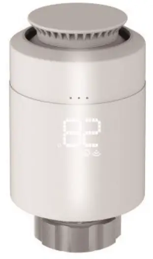
Introduction
The TRV based on Z-WaveTM Slave library of V7.16.03. This TRV integrated Z-Wave communication module to connect with Z-Wave gateway.
The TRV can be included and operated in any Z-Wave network with other Z-Wave certified devices from other manufacturers and/or other applications. All non-battery operated nodes within the network will act as repeaters regardless of vendor to increase reliability of the network. The TRV is a security Z-Wave device (S0/S2), so a security enabled controller is needed for take full advantage of all functionally for the TRV.
Features
- ⚫ Manual or Z-Wave setpoint set heating control with instant status updates.
- 700 series Z-Wave chip for better range and faster control.
- SmartStart and S2 Security for a safer network.
Technical Specifications
Communication Protocol | Z-TRV-V01 |
| Radio Frequency | 868.42MHz (EU) |
| Wireless Range | Up to 300 feet line of sight |
| Power Source | AA*2 |
| Working current | ~20mA |
| Standby current | ~30uA |
| Temperature setting accuracy | 0.5° C |
| Room temperature display range | 0-50° C |
| Operating temperature range | 5-30° C |
| Operating humidity | Up to 85% non-condensing |
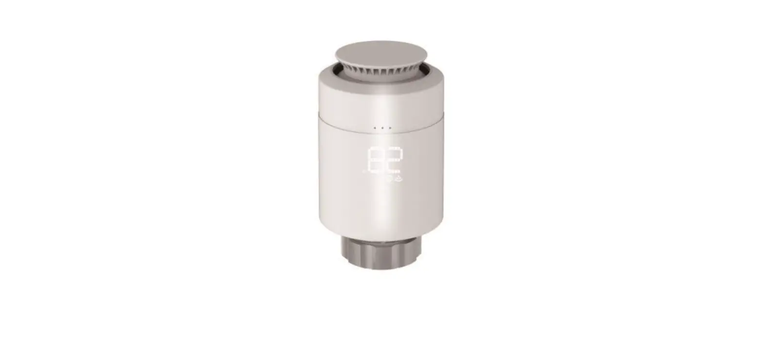
Familiarize yourself with your TRV
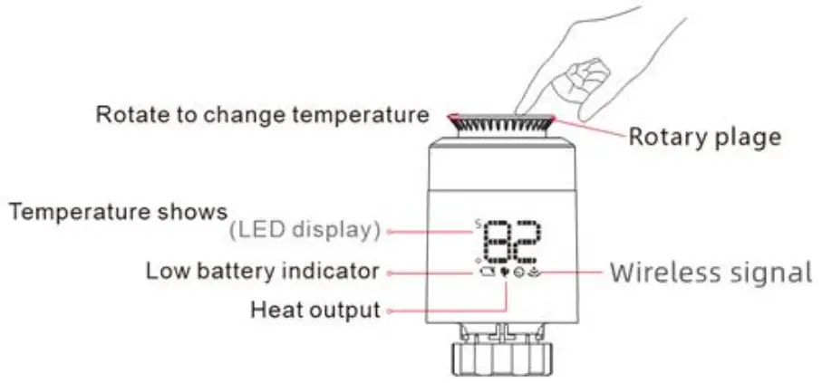
Notice for use
![]() ON/OFF
ON/OFF
The temperature<5°C . display-Or . The temperature>30°C , display ‘OW g ![]() Open window function
Open window function
When use radiator to heating , the window is opened when room temperature drop 6°C in 4 minutes , TRV will close valve automatic,disply will show ‘or , When window is closed , meanwhile room temperature increase 2°C TRV will open valve automatic , back to operation mode .![]() Anti-scale function
Anti-scale function
If radiator not open within two weeks or long time not open will let valve clogged as scale , radiator will be damaged. In order to let radiator to use normally TRV will open valave running 30 seconds every two weeks , display will show ‘Rs’ , when run finished will recovery running condition .![]() Child lock function
Child lock function
In order to prevent TRV setting from children, it could activate child lock functin by long press rotary plate until display show” LC “. Long press rotrary plate again over lOs to unlock.![]() Anti-freezing function
Anti-freezing function
In the power off state. the screen show “iti-Anti-freezing function: the valve will be opened when the temperature is below 5°C , when the temperature risees to 8°C . the valve will be closed.![]() Alarm
Alarm
In the normal operation range: NTC sensor damage , display: Er![]() Low power alarm
Low power alarm
When the battery voltage is extremely low , display the alarm symbol ED , which remind that the user shall replace battery.
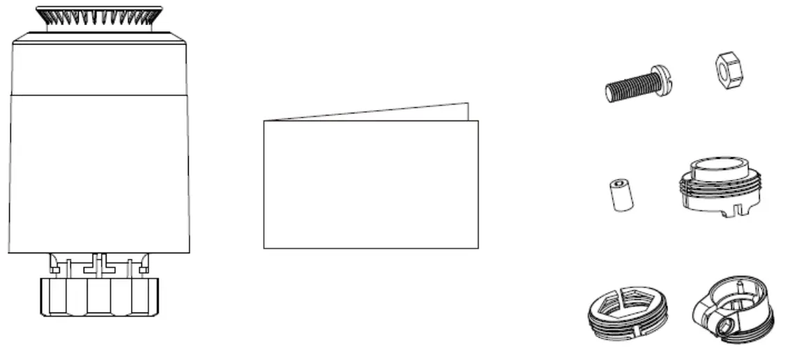
Installation
IMPORTANT: Please include your TRV to the network (refer to 4.1) before doing the installation. Below is the installation process:
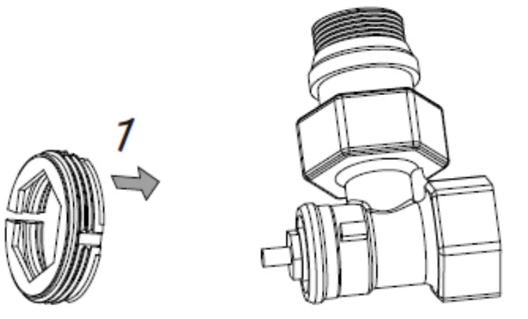
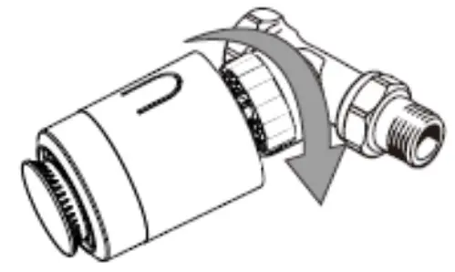
- Choose the right adapter and install it to the valve if the TRV can not install to your valve directly.
Adapter Selection
Pls confirm valve diameterDanfoss Caleffi Giacomini ½ valve (RA) ½ valve ½ valve + short plunger 


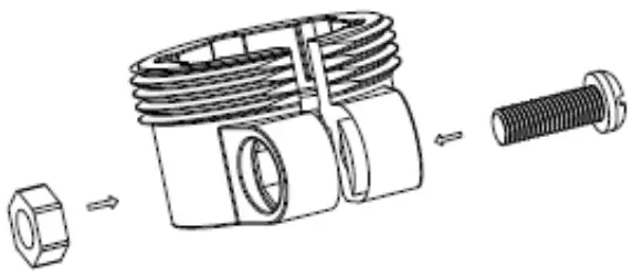
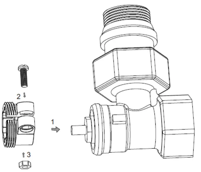
Adapter Installation
Danfoss: 1/2 valve(RA)
please tighten the screws after fixing the valve connector
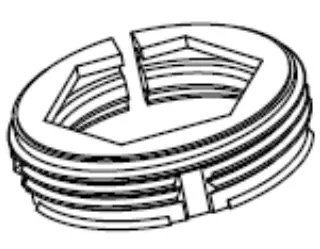
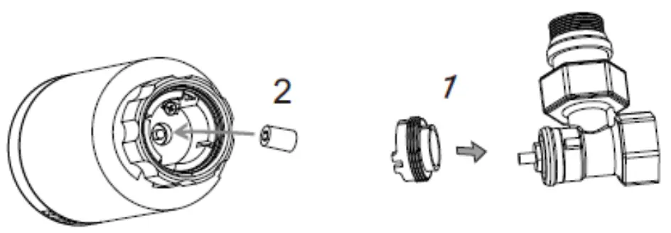
Caleffi 1/2 valve
Adapter please put directly on the valve.
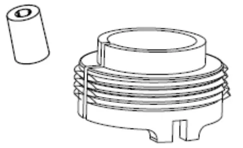
Giacomini 1/2 valve need install short plunger at button of TRV. Accessories,please put directly on the valve.
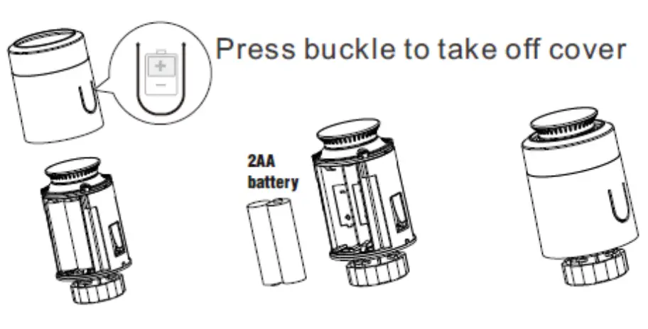
- Take off the batteries and put them on again to REPOWER the TRV;
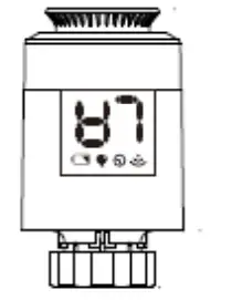
- The screen will blink “LA” until it become solid;
- Install the TRV to the valve;
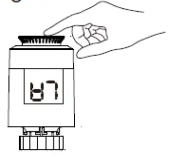
- Click the roraty plate once and the “LA” will start blinking again;
- Installation completed (“LA” disappears and shows the temperature).
- Put battery in battery compartment.

- Display show
 flashing.
- Once valve needle is flush with the base.

- Install TRV with M30*1.5 screw thread interface of valve.Tighten the copper ring.

- Press buttton on rotatory plate lightly’it would flash TRV will match stroke if match successfully, will active initial setting.


Inclusion, Exclusion and Reset
Inclusion
Smart Start enabled products can be added into a Z-Wave network by scanning the Z-Wave QR Code present on the product with a controller providing Smart Start inclusion. No further action is required and the Smart Start product will be added automatically within 10 minutes of being switched on in the network vicinity.
Include the TRV into the Z-Wave network via SmartStart:
- Add TRV DSK into the primary controller SmartStartProvisioning List (If you don’t know how to do this, refer to itsmanual, DSK usually print on the main body).
- Remove the battery from the TRV. A few seconds later, repowered in the TRV.
- The TRV will send “Z-Wave protocol Command Class” frame to start SmartStart Inclusion.
Include the TRV into the Z-Wave network manually:
- . Power on your TRV,
- Set your Z-Wave controller into add/inclusion mode.
- In “
 ” state, short press rotary plate three times until the screen shows “ ”.
 - The screen will show “
 ” after few seconds, which meant the inclusion is successful. And the “
 ” will light on. Otherwise, the inclusion is failed, which you will need to repeat the process form step b.
Exclusion
Exclude TRV from a Z-Wave network:
- Power on your TRV
- Set the Z-Wave primary controller into remove/exclusion mode.
- In “ ” state, short press rotary plate three times until the screen shows “
 ”.
”. - The screen will turn back to“ ” after few seconds, which meant the inclusion is successful. The “ ” light will be off. Otherwise, the exclusion is failed which you will need to repeat the process form step b.
Reset TRV to factory default
In “![]() ” state, press and hold rotary plate for at least 5 seconds and release when the screen will blink “
” state, press and hold rotary plate for at least 5 seconds and release when the screen will blink “ ![]() ”. When the reset is successful, the screen will show “
”. When the reset is successful, the screen will show “![]() ” in solid for 2 seconds then turn off. And TRV will reset itself to factory default by sending a “Device Reset Locally Notification” to gateway.
” in solid for 2 seconds then turn off. And TRV will reset itself to factory default by sending a “Device Reset Locally Notification” to gateway.
Note: Please use this procedure only when the network primary controller is missing or otherwise inoperable.
Security and non-Security features of TRV
This device is a security enabled Z-Wave PlusTM product that is able to use encrypted Z-Wave Plus messages to communicate to other security enabled Z-Wave Plus products. When a node includes into a S2 Z-Wave network, the node supports S2 unauthenticated class, S2 authenticated and so do the supported CCs.
This product can be operated in any Z-Wave network with other Z-Wave certified devices from other manufacturers. All mains operated nodes within the network will act as repeaters regardless of vendor to increase reliability of the network.
Supported Security Levels
- SECURITY_KEY_S0_BIT
- SECURITY_KEY_S2_AUTHENTICATED_BIT
- SECURITY_KEY_S2_UNAUTHENTICATED_BIT
Library
Basic Device Class: BASIC_TYPE_ROUTING_SLAVE
Generic Device Class: GENERIC_TYPE_THERMOSTAT
Specific Device Class: SPECIFIC_TYPE_THERMOSTAT_GENERAL_V2
Commands List
| Command Classes | Version | Required Security Class |
| COMMAND_CLASS_ZWAVEPLUS_INFO_V2 | 2 | None |
| COMMAND_CLASS_TRANSPORT_SERVICE_V2 | 2 | None |
| COMMAND_CLASS_SECURITY_2_V1 | 1 | None |
| COMMAND_CLASS_SUPERVISION_V1 | 1 | None |
| COMMAND_CLASS_APPLICATION_STATUS | 1 | None |
| COMMAND_CLASS_BASIC | 2 | S0 or S2 Authenticated/Unauthenticated |
| COMMAND_CLASS_VERSION_V2 | 3 | S0 or S2 Authenticated/Unauthenticated |
| COMMAND_CLASS_ASSOCIATION_V2 | 2 | S0 or S2 Authenticated/Unauthenticated |
| COMMAND_CLASS_ASSOCIATION_GRP_INFO_V3 | 3 | S0 or S2 Authenticated/Unauthenticated |
| COMMAND_CLASS_MULTI_CHANNEL_ASSOCIATION_V3 | 3 | S0 or S2 Authenticated/Unauthenticated |
| COMMAND_CLASS_MANUFACTURER_SPECIFIC_V2 | 2 | S0 or S2 Authenticated/Unauthenticated |
| COMMAND_CLASS_DEVICE_RESET_LOCALLY_V1 | 1 | S0 or S2 Authenticated/Unauthenticated |
| COMMAND_CLASS_BATTERY_V1 | 1 | S0 or S2 Authenticated/Unauthenticated |
| COMMAND_CLASS_CONFIGURATION_V4 | 4 | S0 or S2 Authenticated/Unauthenticated |
| COMMAND_CLASS_SWITCH_MULTILEVEL_V4 | 4 | S0 or S2 Authenticated/Unauthenticated |
| COMMAND_CLASS_SENSOR_MULTILEVEL_V11 | 11 | S0 or S2 Authenticated/Unauthenticated |
| COMMAND_CLASS_THERMOSTAT_MODE | 3 | S0 or S2 Authenticated/Unauthenticated |
| COMMAND_CLASS_THERMOSTAT_SETPOINT | 3 | S0 or S2 Authenticated/Unauthenticated |
| COMMAND_CLASS_FIRMWARE_UPDATE_MD_V5 | 5 | S0 or S2 Authenticated/Unauthenticated |
| COMMAND_CLASS_POWERLEVEL_V1 | 1 | S0 or S2 Authenticated/Unauthenticated |
| COMMAND_CLASS_INDICATOR_V3 | 3 | S0 or S2 Authenticated/Unauthenticated |
Special Rule of Each Command
Wave Plus Info Report Command Class
Z-Wave Plus Version: 0x02
Role Type: 0x05 (ZWAVEPLUS_INFO_REPORT_ROLE_TYPE_SLAVE_ALWAYS_ON)
Node Type: 0x00 (ZWAVEPLUS_INFO_REPORT_NODE_TYPE_ZWAVEPLUS_NODE)
Installer Icon Type: 0x1200 (ICON_TYPE_GENERIC_THERMOSTAT)
User Icon Type: 0x1200 (ICON_TYPE_GENERIC_THERMOSTAT)
Multilevel Sensor Command Class
Supported the sensor type for Temperature.
Association Command Class
The Thermostat supports 1 association groups and max 5 nodes for each group.
| GroupingIdentifier | MaxNodes | Send Commands |
| Group 1 | 0x05 | 1.Battery ReportThe TRV will send a Battery Report When Battery level change is greater than 5%(configurable) or the report interval is reached. 2.Switch Multilevel ReportThe TRV will send a Switch Multilevel Report when valve opening level changes.3.Sensor Multilevel ReportThe TRV will send a Sensor Multilevel Report When Roomtemperature change is greater than 0.5℃ (configurable) or the |
| report interval is reached. 4.Thermostat Mode ReportThe TRV will send a Thermostat Mode Report when the TRV mode changed. 5. Thermostat Setpoint ReportThe TRV will send a Thermostat Setpoint Report when setting temperature changed.6. Indicator Report |
Basic Command Class
| Value | Description | Function |
| 0x00 | OFF | No Heating, Only Frost-protection |
| 0xFF | Heat Mode | TRV into comfort heating mode.The room temperature will be kept at the configured comfortable level. |
Switch Multilevel Command Class
Allows to request the valve opening in percen 0% represents a fully shut valve. 100 % a fully open valve. The valve opening can be reported on change. If the configuration parameter is set.
Thermostat Mode Command Class
| ThermostatMode Value | Supported Thermostat Mode | Defined By |
| 0x01 | THERMOSTAT_MODE_REPORT_MODE_HEAT_V3 | ZWave Standard |
| 0x00 | THERMOSTAT_MODE_REPORT_MODE_OFF_V3 | ZWave Standard |
Thermostat Setpoint Command Class
Supported the Set point type: THERMOSTAT_MODE_REPORT_MODE_HEAT
Indicator Command Class
The Receptacle support the Indicator Command Class, version 3 and support the Indicator ID 0x50 (Identify) and Properties ID 0x03, 0x04 and 0x05.
Configuration Command Class
| # | Name | Size | Range | Description | Default |
| 1 | Open window detect function | 1 | 0~1 | When use radiator to heating,the window is opened,when roomtemperature drop 6℃ in 4 minutes,TRV will close valve automatic,disply will show ” ” ,Whenwindow is closed,meanwhile roomtemperature increase 2℃,TRV will open valve automatic,back to operation mode.0 = Disable1 = Enable | 0 |
| 2 | Anti-freezing function | 1 | 0~1 | The TRV is at “off” state, the screenshow .Anti-freezing function: the valve will be opened when the temperature isbelow 5℃,when the temperaturerisees to 8℃,the valve will be closed. 0 = Disable1 = Enable | 0 |
| 3 | Measured temperature offset | 1 | -6~6 | Offsets the measured temperature by- 6.0℃ – (+)6.0℃.0x0 = 0℃ Offset0xFA~0x06 = -6~(+)6℃ Offset | 0 |
| 4 | Set away home mode | 1 | 0~1 | Set away home 0 = No1 = Yes | 0 |
| 5 | Anti-scale function | 1 | 0~1 | If radiator not open within two weeks or long time not open will let valve clogged as scale, radiator will be damaged. In order to let radiator to | 0 |
| use normally, TRV will open valave running 30 seconds every two weeks, display will show “ ”, when run finished will recovery running condition.0 = Disable1 = Enable | |||||
| 6 | Valve opening level report threshold | 1 | 0~100 | Valve opening level change threshold. The unit = %0 = Disable1-99 = Valve opening level | 1 |
| 7 | Temperature auto report interval time | 4 | 0~2678400 | The time interval when to send the temperature report. The unit= second1. Valid values: 0x00-0x28DE80 2.0×00 = Disable | 0 |
| 8 | Temperature change report threshold | 1 | 0~100 | Temperature change threshold. unit 0.1℃0 = Disable | 5 |
| 9 | Battery auto report interval time | 4 | 0~2678400 | The time interval when to send the battery report. The unit= second1. Valid values: 0x00-0x28DE80 2.0×00 = Disable | 0 |
| 10 | Battery change report threshold | 1 | 0~100 | Battery power change threshold. The unit = %0 = Disable | 5 |
| 11 | Enable child lock | 1 | 0~1 | Enable or disable child lock 0 = Disable1 = Enable | 0 |


 Dan_lc-13 Manual")


