![]() Daily Wired Thermostat
Daily Wired Thermostat
User Manual
Cetus Daily Wired Thermostat
The extended manual can be found at: https://manuals.auraton.pl

![]() Producent
Producent
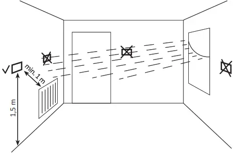
Choosing the right location for the AURATON Cetus
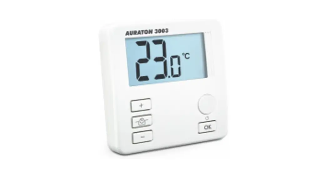
Daily, wired thermostat
AURATON Cetus is a daily, wired thermostat designed to work with a gas or electric heating device.
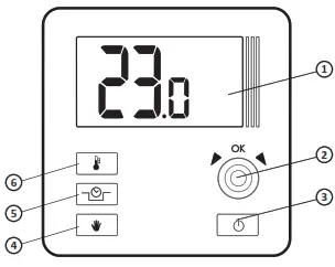
Thermostat
- LCD display
- setting knob with an integrated „OK” button
- ON/OFF button
- Manual mode button
- Temporary temperature reduction mode button
- temperature setting button
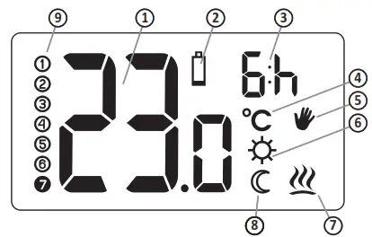
Display
- Temperature
- Low battery (
 )
) - Temporary temperature reduction mode duration indicator
- Temperature unit (Cº)
- The manual control indicator (
 )
) - Temporary temperature reduction mode programming indicator(
 )
) - AURATON Cetus power-on symbol (
 )
) - Temporary temperature
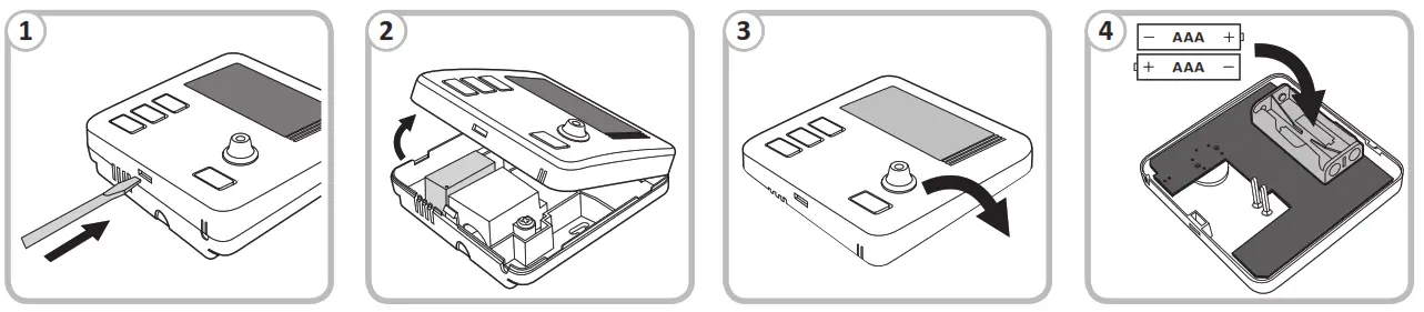
Installing batteries in AURATON Cetus
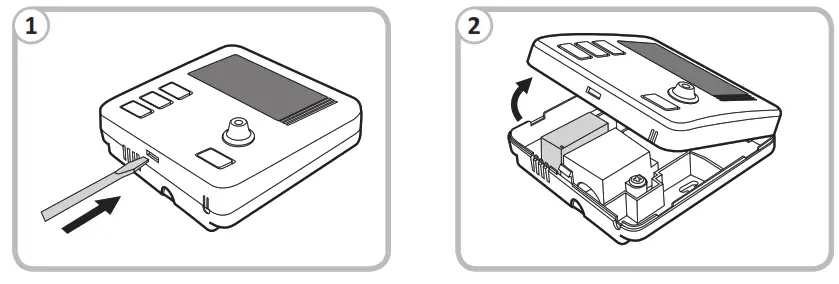
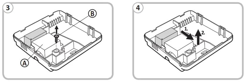
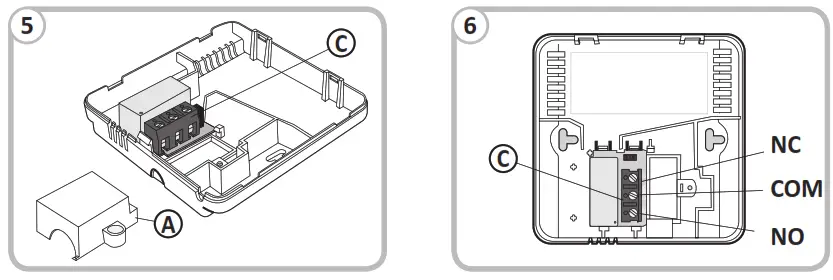
Connecting cables to AURATON Cetus
A – cover;
B – screw;
C – wire terminals
 |  |
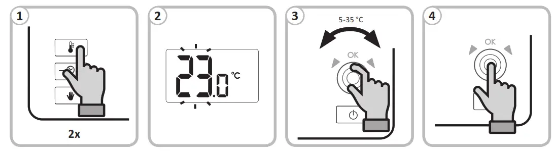
Setting the temperature AURATON Cetus
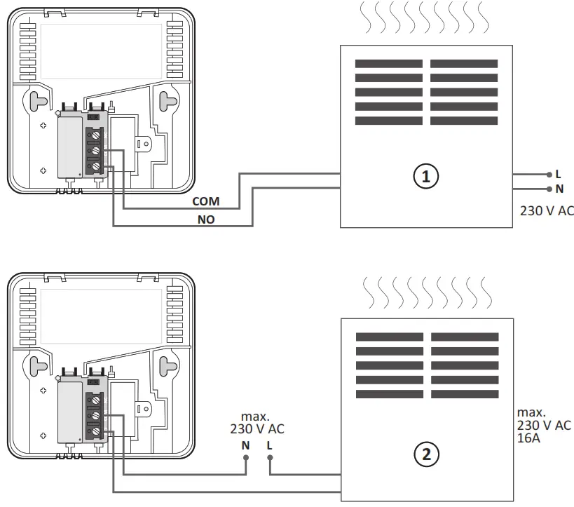
Simplified diagram of connecting the thermostat with the heating device
- Heating device e.g. a gas furnace;
- Electric heating device
Technical specifications
| Power supply: Working temperature range: Signaling the working status: A number of temps. levels: Anti-freeze temperature: Temperature measurement range: Temperature measurement range: Temperature setting accuracy Hysteresis: Relay load capacity: Working cycles: Level of security: Dimensions [mm]: | 2 x AAA (2 x 1.5 V), alkaline 0 – 45 °C LCD 1 2 °C 0 – 35 °C 5 – 35 °C 0,2 °C ±0.2 °C / ±0.4 °C / PWM Max. 250 V AC, max. 16 A Daily IP20 90 x 90 x 36 |
Disposing of the devices![]() The devices are marked with the crossed waste bin symbol. According to European Directive no. 2012/19/UE and the Act concerning used-up electric and electronic equipment, such a marking indicates that this equipment may not be placed with other household-generated waste.
The devices are marked with the crossed waste bin symbol. According to European Directive no. 2012/19/UE and the Act concerning used-up electric and electronic equipment, such a marking indicates that this equipment may not be placed with other household-generated waste.
The user is responsible for delivering the devices to a reception point for used-up electric and electronic equipment.


