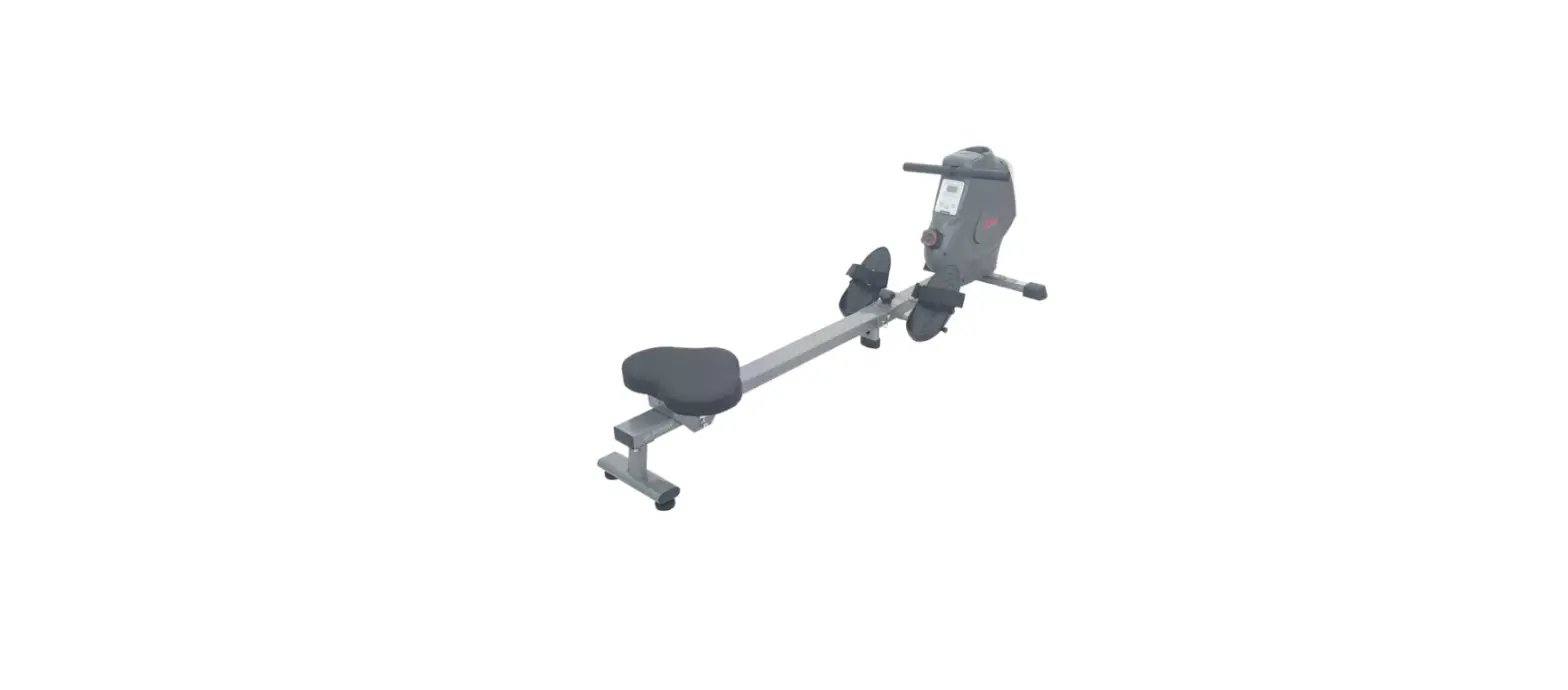
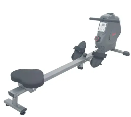
 SUNNY HEALTH FITNESS SF-RW521020 Rowing Machine with Bluetooth
IMPORTANT! Please retain the owner’s manual for maintenance and adjustment instructions. Your satisfaction is very important to us, PLEASE DO NOT RETURN UNTIL YOU HAVE CONTACTED US: [email protected] or 1-877-90SUNNY (877-907-8669).
IMPORTANT SAFETY INFORMATION
We thank you for choosing our product. To ensure your safety and health, please use this equipment correctly. It is important to read this entire manual before assembling and using the equipment. Safe and effective use can only be achieved if the equipment is assembled, maintained, and used properly. It is your responsibility to ensure that all users of the equipment are informed of all warnings and precautions.
- Before starting any exercise program, you should consult your physician to determine if you have any medical or physical conditions that could put your health and safety at risk or prevent you from using the equipment properly. Your physician’s advice is essential if you are taking medication that affects your heart rate, blood pressure, or cholesterol level.
- Be aware of your body’s signals. Incorrect or excessive exercise can damage your health. Stop exercising if you experience any of the following symptoms: pain, tightness in your chest, irregular heartbeat, shortness of breath, lightheadedness, dizziness, or feelings of nausea. If you do experience any of these conditions, you should consult your physician before continuing with your exercise program.
- Keep children and pets away from the equipment. The equipment is designed for adult use only.
- Use the equipment on a solid, flat-level surface with a protective cover for your floor or carpet. To ensure safety, the equipment should have at least 2 feet (60 CM) of free space all around it.
Ensure that all nuts and bolts are securely tightened before using the equipment. The safety of the equipment can only be maintained if it is regularly examined for damage and/or wear and tear. - Always use the equipment as indicated.
- If you find any defective components while assembling or checking the equipment, or if you hear any unusual noises coming from the equipment during exercise, discontinue use of the equipment immediately and do not use it until the problem has been rectified.
Wear suitable clothing while using the equipment. Avoid wearing loose clothing that may become entangled in the equipment. - Do not place fingers or objects into the moving parts of the equipment.
- The maximum weight capacity of this unit is 285 pounds(130 kg).
- This equipment is not suitable for therapeutic use.
- To avoid bodily injury and/or damage to the product or property, proper lifting and moving are required.
- Your product is intended for use in cool and dry conditions.
- You should avoid storage in extremely cold, hot or damp areas as this may lead to corrosion and other related problems.
- This equipment is designed for indoor and home use only; it is not intended for commercial use.
PRE-ASSEMBLY CHECKLIST
Before you start to assemble, please make sure all parts are included.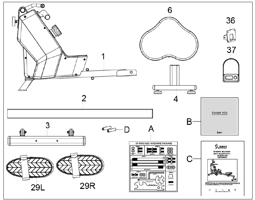
| No. | Description | Spec. | Qty. | No. | Description | Spec. | Qty. | |
| 1 | Main Frame | 1 | 37 | Computer | 1 | |||
| 2 | Sliding Rail | 1 | 29L/R | Pedal | 2 | |||
| 3 | Front Stabilizer | 1 | A | Hardware Package | 1 | |||
| 4 | Rear Stabilizer | 1 | B | Thank You Card | 1 | |||
| 6 | Seat | 1 | C | Manual | 1 | |||
| 36 | Computer Support | 1 | D | Battery | 2 |
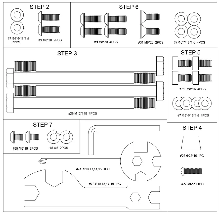
HARDWARE PACKAGE 
Ordering Replacement Parts (U.S. and Canadian Customers only)
Please provide the following information in order for us to accurately identify the part(s) needed:
- The model number (found on the cover of the manual)
- The product name (found on the cover of the manual)
- The part number found on the “EXPLODED DIAGRAM” and “PARTS LIST” (found near the front of the manual)
ASSEMBLY INSTRUCTIONS
We value your experience using Sunny Health and Fitness products. For assistance with parts or troubleshooting, please contact us at [email protected] or 1-877-90SUNNY (877-907-8669). 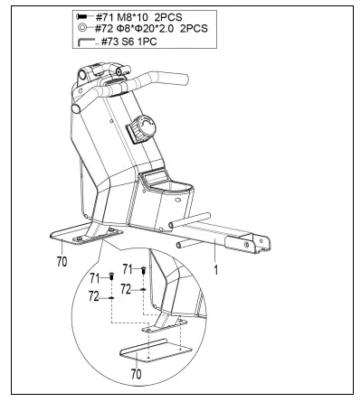
STEP 1
Unscrew 2 Screws (No. 71), 2 Plastic Washers (No. 72), and 1 Shipping Board (No. 70) from Main Frame (No. 1) with Allen Wrench (No. 73).
You may save these parts Screws (No. 71), Plastic Washers (No. 72), and Shipping Board (No. 70) in case you would like to repackage and transport this equipment in the future.
STEP 2
Attach Front Stabilizer (No. 3) to Main Frame (No. 1) using 2 Bolts (No. 9) and 2 Washers (No. 7). Tighten and secure with Allen Wrench (No. 73).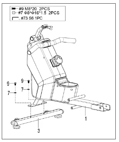
We value your experience using Sunny Health and Fitness products. For assistance with parts or troubleshooting, please contact us at [email protected] or 1-877-90SUNNY (877-907-8669).
STEP 3
Attach 2 Bolts (No. 28) into the bottom hole in position B of the Main Frame (No. 1), with Spanner (No. 75). Insert 2 Bolts (No. 28) into the upper hole in position A of the Main Frame (No. 1) through the 2 Pedals (No. 29L/R). Tighten with Spanner (No. 75).
NOTE: The 2 Pedals (No. 29L/R) should rest on Bolts (No. 28) that are in position B.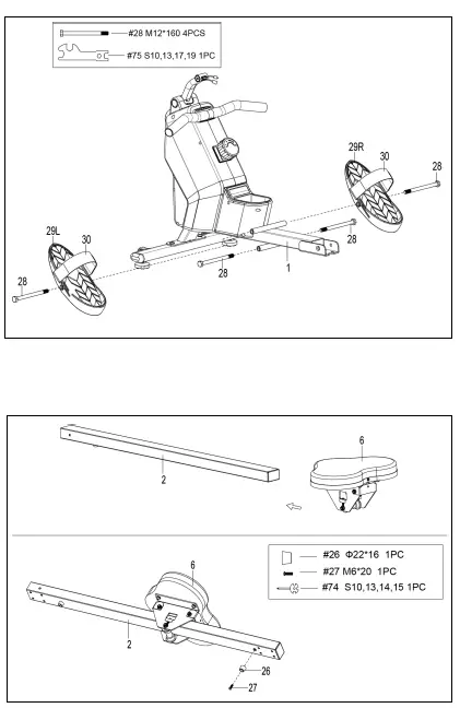
STEP 4
Slide the Seat (No. 6) into the Sliding Rail (No. 2). Attach 1 Limit Mat (No. 26) onto the Sliding Rail (No. 2) using 1 Screw (No. 27), then tighten with Spanner (No. 74).
STEP 5
Attach the Rear Stabilizer (No. 4) to the Sliding Rail (No. 2) using 4 Bolts (No. 21) and 4 Washers (No. 7). Tighten and secure with Allen Wrench (No. 73).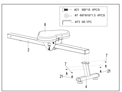
STEP 6
Attach the Sliding Rail (No. 2) to the Main Frame (No. 1) by securing 2 Bolts (No. 31) onto the left and right sides of the Main Frame (No. 1). Don’t tighten the Bolts (No. 31) now. Secure 4 Bolts (No. 9) and 4 Washers (No. 7) to the bottom of the Main Frame (No. 1). Tighten all the 4 Bolts (No. 9) and 2 Bolts (No. 31) with Allen Wrench (No. 73) now.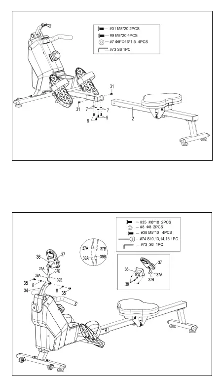
STEP 7
Remove 4 Bolts (No. 38) from the back of the Computer (No. 37) with the Spanner (No. 74). First insert Computer Wires A/B (No. 37A/B) through Computer Support (No. 36), then attach the Computer (No. 37) to the Computer Support (No. 36) using 4 Bolts (No. 38) that were removed. Tighten and secure with Spanner (No. 74). Connect the Sensor Wire A (No. 39A) to Computer Wire A (No. 37A) and connect Sensor Wire B (No. 39B) to Computer Wire B (No. 37B). Next, insert the connected wires into Computer Supporting Tube (No. 34). Attach the Computer Support (No. 36) to Computer Supporting Tube (No. 34) using 2 Bolts (No. 35) and 2 Spring Washers (No. 8). Tighten and secure with Allen Wrench (No. 73) and Spanner (No. 74).
ADJUSTMENTS &USAGE GUIDE
CAUTION! Moving parts, such as the seat, can cut and crush. Keep hands clear of the sliding rail during use!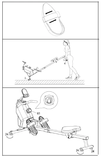
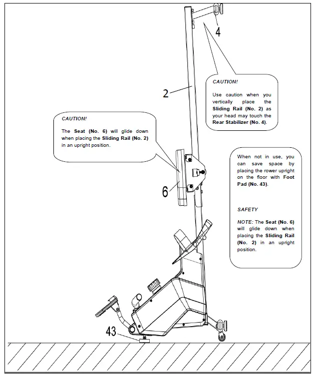
- PEDAL STRAP ADJUSTMENT
The pedal straps is adjustable and can be personalized to fit the user’s foot size.
NOTE: To avoid injury, please adjust the pedal straps to the user’s foot before exercise. - MOVING THE ROWER
To move the rower, lift up the Rear Stabilizer (No. 4) until the transportation wheels on the Front Stabilizer (No. 3) touch the ground. With the transportation wheels on the ground, you can transport the rower to the desired location with ease. - ADJUSTING THE BALANCE AND RESISTANCE
Adjust the Foot Pads (No. 24) on the rear support of the rower if the rower is unbalanced during use. Rotate the Tension Control Knob (No. 61) clockwise to increase the level of resistance. Rotate the Tension Control Knob (No. 61) counter-clockwise to decrease the level of resistance. Tension levels are set at Level 1 being the lowest and Level 8 being the highest.
STORAGE GUIDE
BATTERY INSTALLATION & REPLACEMENT
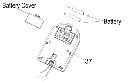
BATTERY INSTALLATION
- Take out 2 AAA batteries from the computer box.
- Press the buckle of the battery cover on the back of the Computer (No. 37), then remove the battery cover.
- Install 2 AAA batteries into the battery case on the back of the Computer (No. 37). Pay attention to the battery + and – poles before installing.
- Press the buckle of the battery cover, then put the battery cover back to the back of the Computer (No. 37).
The installation is complete!
- Press the buckle of the battery cover on the back of the Computer (No. 37), then remove the battery cover.
- Remove the 2 old AAA batteries in the battery case and install 2 new AAA batteries into the battery case on the back of the Computer (No. 37). Pay attention to the battery + and – poles before installing.
- Press the buckle of the battery cover, then put the battery cover back to the back of the Computer (No. 37).
The replacement is complete!
NOTE: Always change both batteries at the same time. Do not mix battery types and do not mix old and new batteries. Dispose of batteries according to your state and regional guidelines.
EXERCISE COMPUTER 
KEY FUNCTIONS
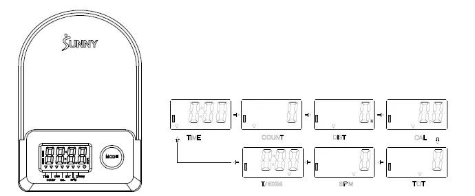
Press the MODE key to select and lock on a function for the following sequence: Press and hold the MODE key for 3 seconds to reset the value to zero (without TOT).
LEEP MODE
The system turns on when the MODE key is pressed and the system senses a signal input from the sensor. All of the values will be reset to zero (without TOT) The system turns off automatically when the sensor has no signal input or no key is pressed for approximately 4 minutes.
FUNCTIONS
- SCAN: Display changes according to the next diagram every 6 seconds.
- COUNT: The current count from starting the exercise.
- DIST: The current distance from starting the exercise.
- TIME: The total working times elapsed from starting the exercise.
- TOTAL COUNT (TOT): The total count from first inserting batteries
- CALORIES: The calorie burned from starting exercise.
- SPM: Number of strokes per minute, indicating the stroke speed during exercise.
- T/500M: The time for 500 meters during exercise
BATTERY INSTALLATION & REPLACEMENT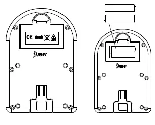
| SPECIFICATION | |
| SCAN | 6S |
| TIME | 99M:59S |
| COUNT | 0~9999 |
| DIST | 0~9999 Meters |
| TOT | 0~9999 |
| CALORIES | 0.0~999.9 Kcal |
| SPM | 0~299 |
| BATTERY | SIZE-AAA *2 |
| Operating temperature | 0~40℃(32℉-104℉) |
| Storage temperature | -10~60℃(14℉-140℉) |
APP CONNECTION
- Scan the QR code below to download the SunnyFit app onto your mobile device.

- If this is your first time using the SunnyFit app, follow the in-app instructions to register for your free SunnyFit account and log in.
- Ensure that the Bluetooth function is turned on from your mobile device.
- To connect the equipment to the SunnyFit app:
- From the “Workout” tab, press the “Search” button to search for your equipment.
- Once your equipment appears on the list, tap the “Select” button to confirm.
- Note: If your equipment does not appear on the “Searching for Equipment” list, check the EXERCISE COMPUTER on your equipment to ensure that it is not in sleep mode and your phone’s Bluetooth function is on, then tap “Retry” to search again.
- Once your equipment shows up on the “Workout” tab as “Currently Selected”, your equipment is now ready to display, track, and record your equipment’s workout stats on the app!
- If you are unable to replicate these steps or have any other issues with the SunnyFit app, please contact SunnyFit support at [email protected], or use the in-app “Contact Us” form to request support (“Me” tab -> “Contact Us”).

EXPLODED DIAGRAM 
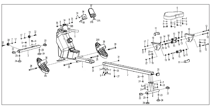
EXPLODED DIAGRAM 
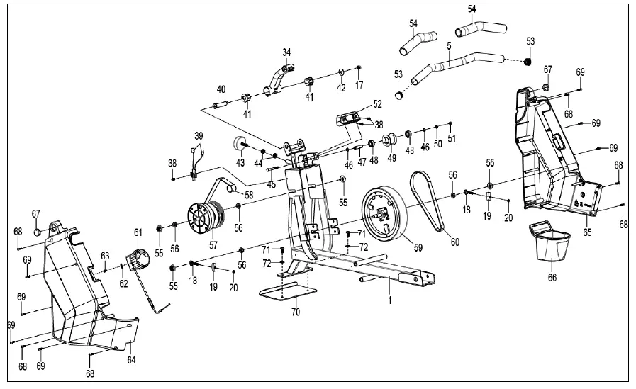
PARTS LIST
| No. | Description | Spec. | Qty. | No. | Description | Spec. | Qty. | |
| 1 | Main Frame | 1 | 39 | Sensor Wire | L=310mm | 1 | ||
| 2 | Sliding Rail | 1 | 39A | Sensor Wire A | 1 | |||
| 3 | Front Stabilizer | 1 | 39B | Sensor Wire B | 1 | |||
| 4 | Rear Stabilizer | 1 | 40 | Bolt | Φ14*77.5*M8 | 1 | ||
| 5 | Handlebar | Φ28*1.5 | 1 | 41 | Axle Sleeve | 2 | ||
| 6 | Seat | 1 | 42 | Big Washer | Φ8*Φ25*2.0 | 1 | ||
| 7 | Washer | Ф8*Ф16*1.5 | 19 | 43 | Foot Pad | M8*30*Φ52*19 | 1 | |
| 8 | Spring Washer | Ф8 | 6 | 44 | Nut | M8*B4 | 2 | |
| 9 | Bolt | M8*20 | 10 | 45 | Bolt | M6*55 | 1 | |
| 10 | Seat Supporting Board | 2 | 46 | Shaft Snap Ring | 2 | |||
| 11 | U Shape Bracket | 2 | 47 | Belt Pulley Shaft | 1 | |||
| 12 | Bolt | M8*100 | 3 | 48 | Bearing | 6000 | 2 | |
| 13 | Spacer | Ф15*Ф8*4 | 6 | 49 | Mesh Belt Pulley | 1 | ||
| 14 | Bearing | 608 | 6 | 50 | Washer | Φ6*Φ12*1.0 | 1 | |
| 15 | Wheel | 3 | 51 | Nut | M6 | 1 | ||
| 16 | Casing Pipe for Idler Wheel | 3 | 52 | Handle Guide | 1 | |||
| 17 | Nut | M8 | 6 | 53 | Round End Cap | 2 | ||
| 18 | Adjusting Screw | M6*36 | 4 | 54 | Foam Grip | Φ27*Φ33*244 | 2 | |
| 19 | U Shape Baffle | 4 | 55 | Nut | M10*1.0*9 | 4 | ||
| 20 | Nut | M6 S10 | 4 | 56 | Nut | M10*1 | 4 | |
| 21 | Bolt | M8*16 | 4 | 57 | Volute Spring Complete Set | 1 | ||
| 22 | End Cap | 4 | 58 | Mesh Belt | 1 | |||
| 23 | Nut | M8 | 4 | 59 | Inertial Wheel | 1 | ||
| 24 | Foot Pad | φ38*18-M8*25 | 4 | 60 | Belt | 220PJ | 1 | |
| 25 | Square Plug | 1 | 61 | Tension Control Knob | L=310mm | 1 | ||
| 26 | Limit Mat | Ф22*16 | 2 | 62 | Washer | Φ5 | 1 | |
| 27 | Screw | M6*20 | 2 | 63 | Bolt | M5*12 | 1 | |
| 28 | Bolt | M12*160 | 4 | 64 | Left Cover | 1 | ||
| 29L/R | Pedal | 2 | 65 | Right Cover | 1 | |||
| 30 | Pedal Strap | 2 | 66 | Bottle holder | 1 | |||
| 31 | Bolt | M8*20S6 | 2 | 67 | Cover | 2 | ||
| 32 | Bolt | M8*40 | 2 | 68 | Screw | ST4.2*20 | 6 | |
| 33 | Transportation Wheel | 2 | 69 | Screw | ST4.2*25 | 7 | ||
| 34 | Computer Supporting Tube | 1 | 70 | Shipping Board | 1 | |||
| 35 | Bolt | M8*10 | 2 | 71 | Screw | M8*10 | 2 | |
| 36 | Computer Support | 1 | 72 | Plastic Washer | Ф8*Ф20*2.0 | 2 | ||
| 37 | Computer | 1 | 73 | Allen Wrench | S6 | 1 | ||
| 37A | Computer Wire A | 1 | 74 | Spanner | S10,13,14,15 | 1 | ||
| 37B | Computer Wire B | 1 | 75 | Spanner | S10,13,17,19 | 1 | ||
| 38 | Bolt | M5*10 | 7 |


