OPERATOR’S MANUAL
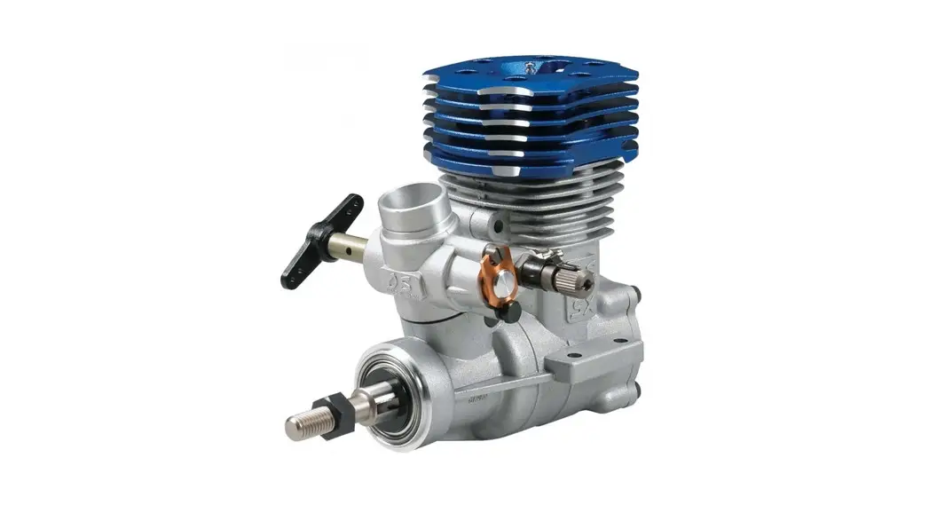
FZ120 Supercharged
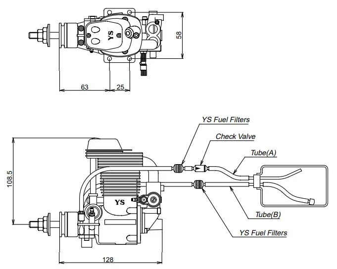
fig.1
 SPECIFICATIONS
 SPECIFICATIONS
| Bore | 30.4mm |
| Stroke | 27.5mm |
| Displacement | 19.96cc |
| weight | 880g |
| Practical rpm | 2,000 -12,500rpm |
FEATURES
The FZ120 was designed for the pattern competition, scale, and large sports models. As aircraft increases in size, so does the need for power.
With a few modifications internally, YS was able to generate more power in the same 120 case. The YS 4 cycles are so unique, almost every square inch is used in some way to produce power.
- Supercharged
- Fuel Injected
- Regulated and Pressurized Fuel System
- High and Low-Speed Adjustments
GLOW PLUG
Select the most appropriate glow plug from those designed specifically for 4 cycle engines. Glow plug selection greatly affects the maximum engine output and low idle. If RPMs decrease or stop when the booster cord is removed, replace the plug. We recommend the OS Type F plug for maximum performance.
INSTALLATION
- Connect the engine to the tank as shown in fig.1.Since high pressure is applied to the tank, tighten all connections carefully. Care must be taken to prevent pressure leakage due to under-tightening of the check valve or by kinking the fuel lines.
- Always use a fuel filter. We recommend the YS filter.
- Match the direction of the check valve arrow in fig.1, with the arrow facing towards the tank.
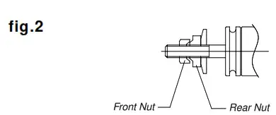
PROPELLER INSTALLATION
Due to the high torque of the 120 engine, we have equipped it with a double locknut system for safety.
- Mount the propeller and tighten the rear nut. Next, tighten the front nut as shown in fig.2. The rear nut has an offset shoulder so the front nut will secure itself to the rear nut.
- Select a good quality propeller that will allow the engine to run at maximum speed between 8,000 to 9,000rpm range. We recommend
sizes 14×12~14,15×10~12, 16×8~10.
STARTUP
- Remove tube A from the check valve, (CAUTION) Tank pressure must be released first before tube B is opened. Remove tube B and begin to fill the fuel tank.
- Open the high-speed needle 2 1/2 turns from the closed position.
- Open the throttle fully and slowly turn the propeller 10 times. This will prime the engine and pressurized the fuel tank.
- Close the throttle to the idle position and connect the glow driver.
The engine is now ready for starting.
DO NOT ATTEMPT TO START THE ENGINE AT FULL THROTTLE, AS THIS IS VERY DANGEROUS. ALWAYS USE EXTREME CAUTION WHEN THE ENGINE IS RUNNING.
BREAK-IN
To maximum engine performance and increase durability, please follow this break-in procedure.
- Use the same size (or slightly smaller) propeller than you intend to use in flying.
- Use a good quality fuel that contains 15-30% nitromethane and oil content of Low Viscosity oil 20-24% oil. Synthetic or castor oil can be used, or a combination of both.
DO NOT USE FOUR-CYCLE FUEL DUE TO LOW OIL CONTENT. - After the engine has started, slowly bring the throttle up to full.
Set high-speed needle so it is running at a good rich setting without the glow driver. Run engine at this setting for approximately 20
minutes with the throttle moving from low to high speed. - After the initial 20-minute break-in, mount the engine in the aircraft and set the high speed to a richer than a normal setting for the first 10 flights. This will help to lubricate all moving parts.
HIGH-SPEED NEEDLE ADJUSTMENT
- Adjustment of the high speed is done by the carburetor needle valve.
When the needle valve is turned clockwise, the mixture is leaner. When it is turned counterclockwise, the mixture is richer. A good starting position for the high-speed needle valve is 2 1/2 turns open from the full close position. - When the engine is started, open the throttle gradually. Next, find the peak position (highest RPM) by adjusting the needle valve. Then the needle valve should be opened approximately 1/8-1/4 turns from full RPM to achieve the best performance. The engine may stop if the throttle is opened to full immediately after starting. Wait until the engine has to warn up to and pressure has developed in the tank.
LOW-SPEED ADJUSTMENT
This engine is equipped with a new low-speed needle valve to adjust the mixture from low to mid throttle. See fig.1 for location.
- The factory starting position is 1 1/2 turns open from the fully closed position. The low-speed needle should be set after the high speed the needle has been adjusted.
- Close the throttle gradually to an idle (approximately 2,000rpm). Let it idle for 15-20 seconds and then slowly advance the throttle.
The adjustment is set when low to high speed has a smooth transition. - If the engine is running rough at idle or too rich, turn the low-speed needle counterclockwise to lean out the low end.
- If the engine speeds up at idle, the low-speed mixture is to lean.
Turn the low-speed needle clockwise to richen the mixture. - If the engine is to lean on the low end, it can detonate and stop when transitioning from low to high RPM.
REGULATOR ADJUSTMENT
The regulator is preset at the factory. The top of the brass adjusting screw is flush with the top of the regulator housing. Turning the egulator screw will not change the pressure the engine develops. The adjustment screw is used to adjust the amount of fuel to the carburetor. Turning the screw in will decrease the amount of fuel and turning the screw out will increase the amount of fuel to the carburetor.
fig.3
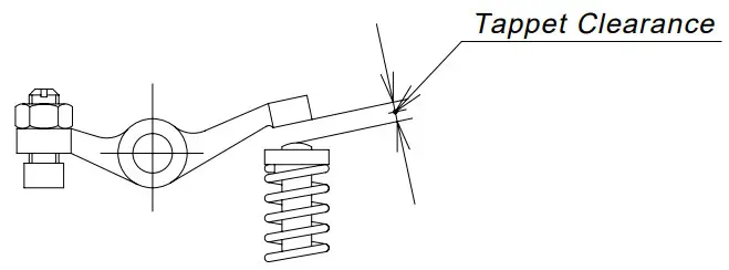
TAPPET ADJUSTMENT
Tappet clearance is preset at the factory. Adjustment if needed should be checked after the initial break-in. For maximum performance, valves should be checked as normal maintenance.
- Clearance adjustment should be done when the engine is cool.
- The proper clearance should be set at 0.04-0.1mm or 0.002-0.004.
The adjustment is achieved by losing the locknut (fig.3) and turning the adjustment screw. The engine must be at the top dead center on the compression stroke before any adjustments is made.
CAM GEAR TIMING
If for some reason you have to disassemble your engine, please follow these important steps on reassembling the cam gear.
- Remove the carburetor and backplate assembly. Notice the impression mark or dot opposite the rod journal on the crankshaft. This
mark is to point straight down or lined up with the outer case seam line at the bottom. - Reinstall the cam with the dot facing you and is pointing slightly to the left. This will allow the cam to turn to the right when properly installed.
The dot should be pointing starting up when the cam is fully installed.
Reinstall cam cover and timing is now set.
DIAPHRAGM AND CHECK VALVE DISASSEMBLY
Diaphragm;
- Remove the regulator assembly by removing the two Allen head screws.
- Disassemble the regulator and clean with alcohol or appropriate cleaner.
- When reinstalling the regulator, use a new gasket and note that the small casting tab on the regulator goes towards the propeller.
Check Valve;
- Open the check valve by rotating the body counterclockwise.
Note the small clear silicone disc. DO NOT LOSE. - Clean and reassemble. Check to make sure air will only pass through the check valve one way.
IMPORTANT! Silicone rubber is used in the YS engine. Only use glow fuel or methanol for cleaning. Gasoline and other volatile solutions will damage the silicone if used. Do not use petroleum-based oils as after run lubricants.
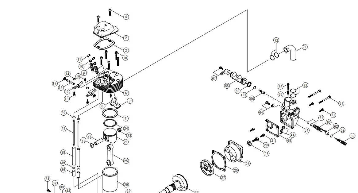
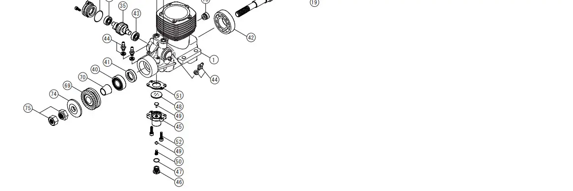
FZ120 Parts LIST
| # | Part# | Description | QTY |
| 1 | F1,801 | Crankcase | 1 |
| F1202S | Head Cover Set | ||
| 2 | F1,202 | Head Cover | 1 |
| 3 | F1,203 | Head Cover Gasket | 1 |
| 4 | F1,204 | Valve Cover Screw Set | 2 |
| 5 | F1,205 | Head Gasket | 1 |
| F1806A | Head Assembly | ||
| 6 | F1,806 | Cylinder Head | 1 |
| 7 | F1,407 | Intake Valve | 1 |
| 8 | F1,408 | Exhaust valve | |
| 9 | F1,409 | Valve Spring Set | 2 |
| 10 | F1,410 | Spring Retainer Set | 2 |
| 11 | F1,411 | Valve Spring Retainer Clips | 4 |
| 12 | F1,212 | Rocker Arm Set | 2 |
| 13 | F1,213 | Tappet Adjusting Screw Set | 2 |
| 14 | F1,214 | Tappet Adjusting Rock Nuts | 2 |
| 15 | F1,215 | Rocker Arm Shaft | 1 |
| 16 | F1,216 | Rocker Arm Shaft Screw | 1 |
| 17 | F1,217 | E Ring Set | 2 |
| 18 | F1,218 | Head Screws | 5 |
| 19 | F1,919 | Crankshaft | 1 |
| 20 | F1,520 | Cylinder Liner | 1 |
| 21 | F1,421 | Piston | 1 |
| 22 | F1,222 | Wrist Piston | 1 |
| 23 | F1,323 | Wrist Pin Retainer Set | 2 |
| 24 | F1,224 | Piston Ring | 1 |
| 25 | F1,225 | Connecting Rod | 1 |
| F1826A | Back Plate Assembly | ||
| 26 | F1,826 | Back Plate | 1 |
| 27 | F1,427 | Disc valve | 1 |
| 28 | F1,492 | Rear Disc Valve Retainer | 1 |
| 29 | F1,429 | Retainer Screw | 1 |
| 30 | F1,230 | Back Plate Gasket | 6 |
| 32 | F1,232 | Cam Gear Cover | 1 |
| 33 | F1,233 | Cam Gear Cover 0-Ring | 1 |
| 34 | F1,234 | Cam Gear Cover Screw | 2 |
| 35 | F1,535 | Cam gear | 1 |
| 36 | F1,236 | Cam Followers Set | 2 |
| 37 | F1,237 | Push Rod Set | 2 |
| 38 | F1,238 | Push Rod Cover Set | 2 |
| 39 | F1,239 | Push Rod Cover 0-Ring | 4 |
| 40 | F1,240 | Front Bearing | 1 |
| 41 | F9,122 | Front Bearing Oil Seal | 1 |
| 42 | F1,341 | Rear Bearing | 1 |
| 43 | F1,242 | Cam Gear Bearing Set | 2 |
| 44 | F1,243 | Fuel Nipples Set With Washers | 6 |
| F1244A | Regulator Assembly | ||
| 45 | F1,244 | Regulator Body | 1 |
| 46 | F1,245 | Regulator Adjusting Screw | 1 |
| 47 | F1,246 | Regulator Adjusting Screw 0-Ring | 1 |
| 48 | F1,247 | Diaphragm | 1 |
| 49 | F1,248 | Regulator Plunger | 1 |
| 50 | F1,249 | Plunger Spring | 1 |
| 51 | F1,250 | Regulator Gasket | 1 |
| 52 | F1,251 | Regulator Screw Set | 2 |
| F1752A | Carburetor Assembly | ||
| 54 | F1,752 | Carburetor Body | 1 |
| 55 | F1,753 | Throttle Barrel | 1 |
| 56 | F9,156 | Low-Speed Needle Valve | 1 |
| 57 | F9,157 | Low-Speed Needle Valve 0-Ring | 1 |
| F1545S | Needle Valve Assembly | ||
| 58 | F1,545 | High-Speed Needle Valve | 1 |
| 59 | F1,546 | High-Speed Needle Valve 0-Ring | 1 |
| 60 | F1,555 | High-Speed Needle Valve Seat | 1 |
| 61 | F1,556 | Needle Valve Socket 0-Ring Set | 2 |
| 62 | F1,557 | Needle Valve Detent | 1 |
| 63 | F1,483 | Throttle Barrel Seal | 1 |
| 64 | R6124 | Throttle Barrel Retainer | 1 |
| 65 | F1,258 | Throttle Stop Screw | 1 |
| 66 | F1,259 | Throttle Stop Spring | 1 |
| 67 | F1260S | Throttle Arm Set | 1 |
| 68 | F1,463 | Carburetor Gasket | 1 |
| 69 | F1,564 | Drive Washer | 1 |
| 70 | F1,565 | Drive Washer Retainer | 1 |
| 71 | F1,268 | Intake Pipe | 1 |
| 72 | F1,269 | Intake Pipe 0-Ring | 4 |
| 73 | F1,382 | Wrist Pin Access Plug | 1 |
| 74 | F1,266 | Propeller Washer | 1 |
| # | Part# | Description | QTY |
| 75 | F1267 | Propeller Nut Set | 2 |
| F1473S | Gasket Set | 4 | |
| F1574S | O-Ring Set | 14 | |
| F1497S | Muffler Assembly | ||
| F1497 | Muffler | 1 | |
| F1971 | Muffler | 1 | |
| F1498 | Rock Nut | 1 |
WARRANTY
Strict quality control is implemented by our factory in all phases, from parts manufacturing to final assembly. If performance deteriorates or a part fails within one year of purchase due to a manufacturing error, YS will repair or replace the engine at no charge. Warranty will not cover normal wear.
Should the engine be modified or incorrectly assembled, there will be a normal charge for parts and labor. The use of four-cycle fuel due to low oil content will also void the warranty.
 YAMADA MFG.CO.,LTD
67 Tsuchitori Inuyama Aichi 484-0917 JAPAN
TEL: 0568 67 0265 FAX: 0568 67 7801


