![]() The FIRST Name in Towing Products™
The FIRST Name in Towing Products™
INSTALLATION INSTRUCTIONS
Scan for helpful installation tips
http://qr.curtmfg.com/category/Electrical
![]() WARNING: DO NOT EXCEED PRODUCT RATING OR TOW VEHICLE LAMP LOAD RATING, WHICHEVER IS LOWER
WARNING: DO NOT EXCEED PRODUCT RATING OR TOW VEHICLE LAMP LOAD RATING, WHICHEVER IS LOWER
PART NUMBERS
| Pkg# | From Vehicle | To Trailer | Mounting Bracket |
| Single Output | |||
| 57184 | 4-way fla | 7-way RV blade | No |
| 57183 | 4-way fla | 6-way round | No |
| 57185 | 4-way fla | 7-way RV blade | Yes |
| 57626 | 4-way fla | 6-way round | Yes |
| 57676 | 4-way fla | 7-way RV blade | Yes |
Dual Output
| 57604 | 4-way flat | 4-way flat 6-way round | Yes |
| 57624 | 4-way flat | 4-way flat | Yes |
| 6-way round | |||
| 57672 | 4-way flat | 4-way flat 7-way RV blade | Yes |
| 57674 | 4-way flat | 4-way flat | Yes |
| 57102 | 4-way flat | 7-way RV blade 4-way flat | Yes |
| 7-way RV blade |
TOOLS NEEDED
| 1/8″ drill bit Drill Phillips screwdriver Wire stripper Cutting tool | Terminal crimpers Test light Three self-tapping screws, #10 – 1/2″ |
![]() WARNING
WARNING ![]()
Never attach the mounting bracket directly to the hitch by cutting, welding or drilling into the hitch
Be sure of what is behind the surface that you are going to be drilling. Stay clear of brake lines, fuel lines, wiring, or any other components that may harm the operation of the vehicle.
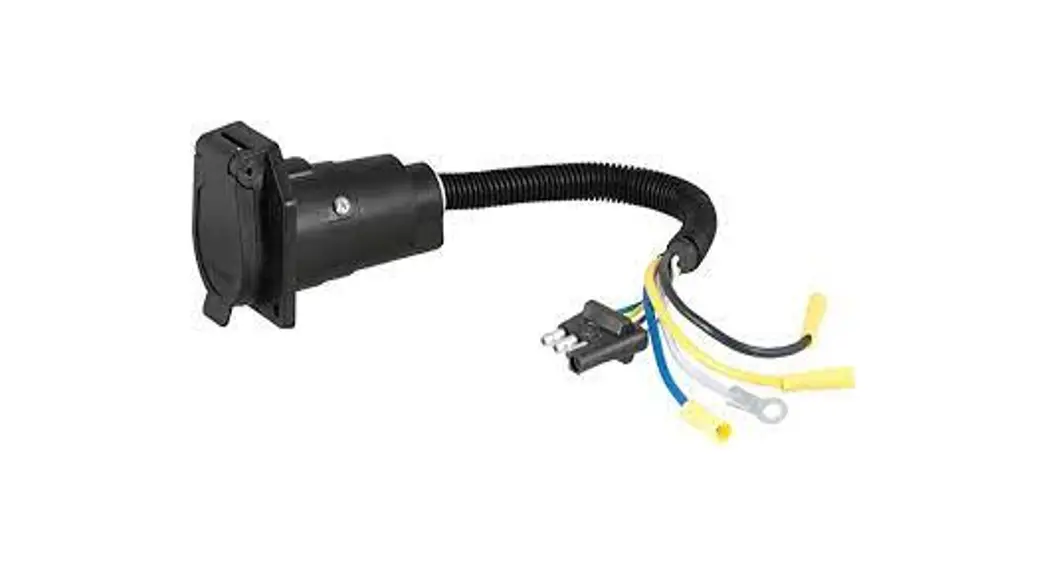
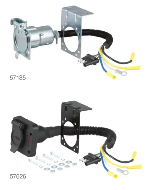
4-WAY FLAT ELECTRICAL ADAPTERS
Single output
Not all part numbers are pictured
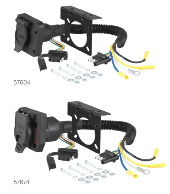
Dual output
Not all part numbers are pictured
 INSTALLATION / SAFETY INSTRUCTIONS
Locate the vehicle’s 4-way flat trailer wiring connector. If the vehicle is not equipped with a 4-way flat trailer connector, you will need to install a custom wiring harness or another 4-way flat trailer connector before continuing with the installation.
Locate a suitable mounting location on the tow vehicle for the combination harness. The mounting bracket (if included) should be attached to the vehicle’s bumper or another suitable surface. The connectors must be mounted in an area that is within reach of the trailer’s wiring harness, near the center of the vehicle.
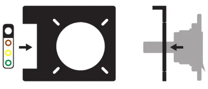
Using the bracket (if included) or equivalent as a template, drill 1/8″ holes into the mounting surface. Secure the bracket to a suitable mounting area on the vehicle by using #10 – 1/2″ self-tapping screws (not included).![]() WARNING: Never attach the mounting bracket directly to the hitch by cutting, welding or drilling into the hitch. Attach the harness connectors to the mounting bracket. For the 6- or 7-way connector, feed the entire harness through the large mounting hole in the bracket and position the connector against the face of the mounting bracket. Using the supplied mounting hardware, attach the connector to the bracket. Slide the 4-way flat connector into the side mounting slot until the connector is secured in place.
WARNING: Never attach the mounting bracket directly to the hitch by cutting, welding or drilling into the hitch. Attach the harness connectors to the mounting bracket. For the 6- or 7-way connector, feed the entire harness through the large mounting hole in the bracket and position the connector against the face of the mounting bracket. Using the supplied mounting hardware, attach the connector to the bracket. Slide the 4-way flat connector into the side mounting slot until the connector is secured in place.
Plug the combination harnesses’ trailer-style 4-way flat connector into the tow vehicle 4-way flat connector. This connection will provide the tail lights, stop lights and turn signal functions. See the below picture.

Determine a suitable grounding point within reach of the combination harness to attach the grounding screw. Be sure that the area is clean of any dirt, debris, or undercoating, and drill a 1/8″ hole.![]() WARNING: Check for miscellaneous items that may be hidden behind or under any surface before drilling to avoid damage and/or personal injury. Attach the combination harnesses’ white wire with the ring terminal to the 1/8″ hole that was drilled, using a #10 – 1/2″ self-tapping screw. This ground connection is required for the harness to work properly. The white wire on the vehicle’s 4-way flat connector will not support the ground (-) functions of the combination harnesses 4-way flat and 6- or 7-way connector.
WARNING: Check for miscellaneous items that may be hidden behind or under any surface before drilling to avoid damage and/or personal injury. Attach the combination harnesses’ white wire with the ring terminal to the 1/8″ hole that was drilled, using a #10 – 1/2″ self-tapping screw. This ground connection is required for the harness to work properly. The white wire on the vehicle’s 4-way flat connector will not support the ground (-) functions of the combination harnesses 4-way flat and 6- or 7-way connector.![]() Failing to properly ground the product can cause loss of warranty, overheating, and potential fire. Using 12 gauge (minimum) wire and butt-connectors, connect the remaining wires to the appropriate functions as listed below.
Failing to properly ground the product can cause loss of warranty, overheating, and potential fire. Using 12 gauge (minimum) wire and butt-connectors, connect the remaining wires to the appropriate functions as listed below.
Yellow – Auxiliary or back-up lights
Blue – Electric brakes
Black – Positive power (+) with appropriate inline fuse
Confirm proper function with a test light or by using a properly functioning trailer. Secure any loose wires by using cable ties or equivalent product.
CURTMFG.COM • NEED ASSISTANCE? • 1.877.287.863 4 • RA


