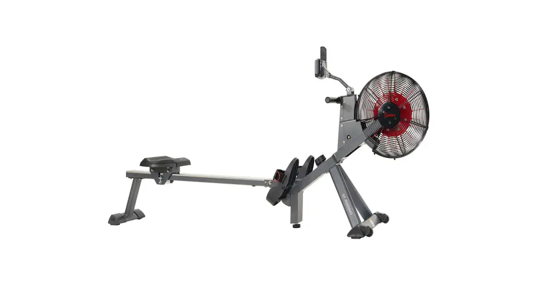
![]() SF-RW5940 MAGNETIC AIR ROWER
SF-RW5940 MAGNETIC AIR ROWER
User Manual
IMPORTANT! Please retain the owner’s manual for maintenance and adjustment instructions. Your satisfaction is very important to us, PLEASE DO NOT RETURN UNTIL YOU HAVE CONTACTED
US: [email protected] or 1- 877 – 90SUNNY (877-907-8669).

IMPORTANT SAFETY INFORMATION
We thank you for choosing our product. To ensure your safety and health, please use this equipment correctly. It is important to read this entire manual before assembling and using the equipment. Safe and effective use can only be achieved if the equipment is assembled, maintained, and used properly. It is your responsibility to ensure that all users of the equipment are informed of all warnings and precautions.
- Before starting any exercise program, you should consult your physician to determine if you have any medical or physical conditions that could put your health and safety at risk or prevent you from using the equipment properly. Your physician’s advice is essential if you are taking medication that affects your heart rate, blood pressure, or cholesterol level.
- Be aware of your body’s signals. Incorrect or excessive exercise can damage your health. Stop exercising if you experience any of the following symptoms: pain, tightness in your chest, irregular heartbeat, shortness of breath, lightheadedness, dizziness, or feelings of nausea. If you do experience any of these conditions, you should consult your physician before continuing with your exercise program.
- Keep children and pets away from the equipment. The equipment is designed for adult use only.
- Use the equipment on a solid, flat-level surface with a protective cover for your floor or carpet. To ensure safety, the equipment should have at least 2 feet (60 CM) of free space all around it.
- Ensure that all nuts and bolts are securely tightened before using the equipment. The safety of the equipment can only be maintained if it is regularly examined for damage and/or wear and tear.
- Always use the equipment as indicated. If you find any defective components while assembling or checking the equipment, or if you hear any unusual noises coming from the equipment during exercise, discontinue use of the equipment immediately and do not use it until the problem has been rectified.
- Wear suitable clothing while using the equipment. Avoid wearing loose clothing that may become entangled in the equipment.
- Do not place fingers or objects into the moving parts of the equipment.
- The maximum weight capacity of this unit is 300 pounds (135 KG).
- The equipment is not suitable for therapeutic use.
- To avoid bodily injury and/or damage to the product or property, proper lifting and moving are required.
- Your product is intended for use in cool and dry conditions. You should avoid storage in extreme cold, hot or damp areas as this may lead to corrosion and other related problems.
- This equipment is designed for indoor and home use only; it is not intended for commercial use.
EXPLODED DIAGRAM 1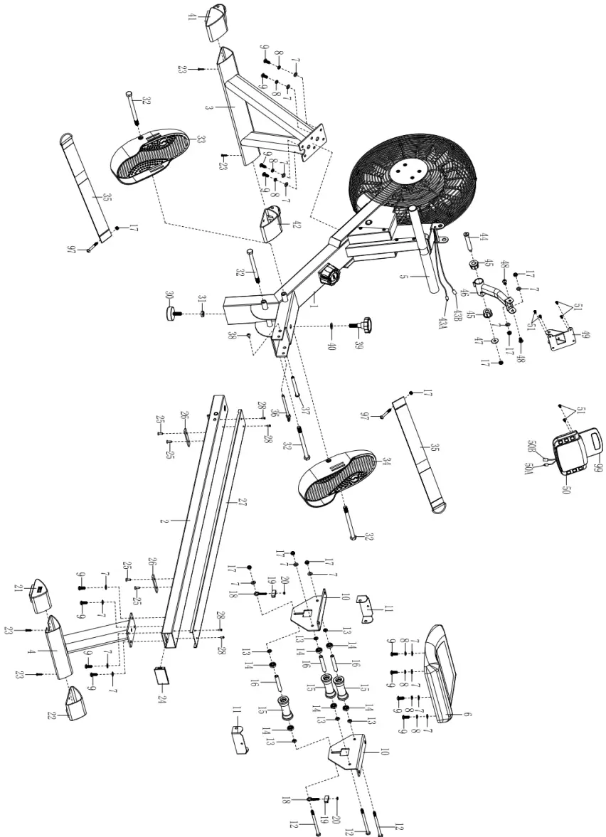 EXPLODED DIAGRAM 2
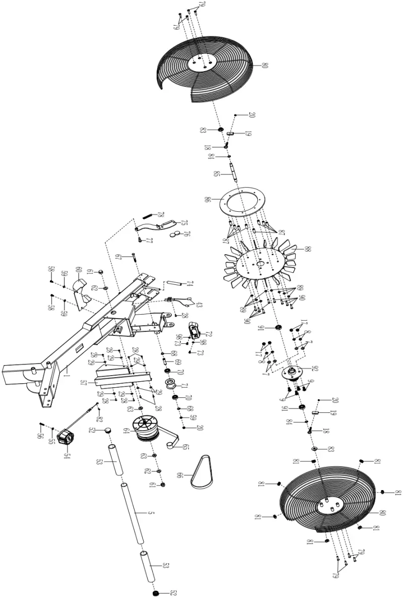
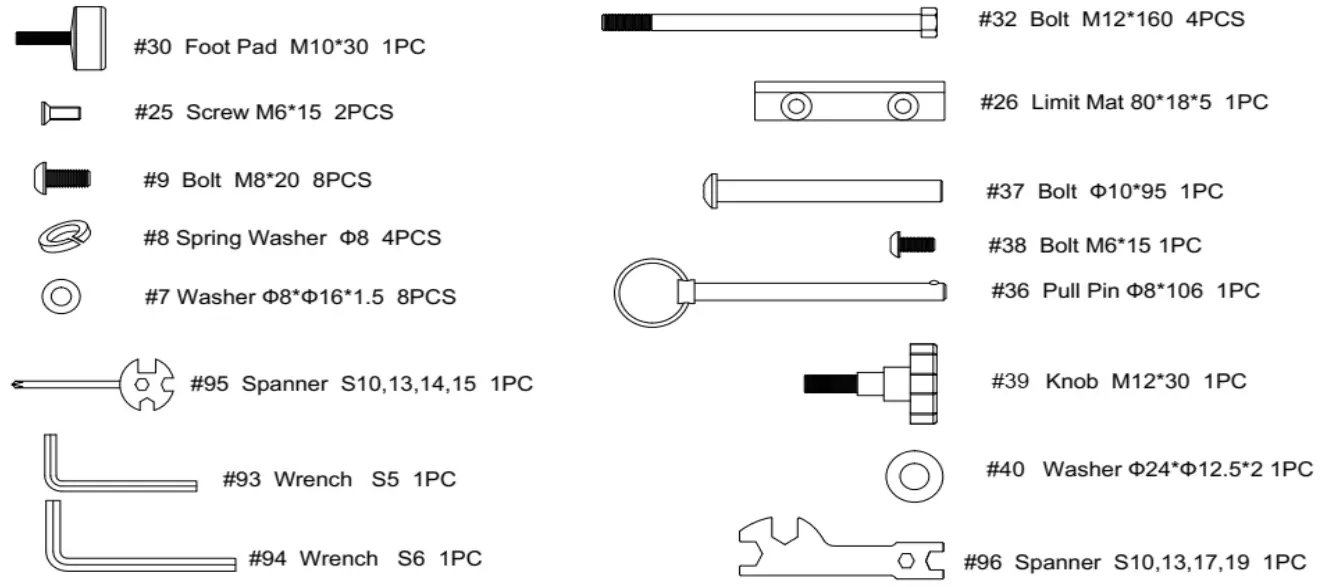
HARDWARE PACKAGE
PARTS LIST
| No. | Description | Spec. | Qty. | No. | Description | Spec. | Qty. | |
| 1 | Main Frame | 1 | 34 | Right Pedal | 1 | |||
| 2 | Sliding Rail | 1 | 35 | Pedal Strap | 2 | |||
| 3 | Front Stabilizer | 1 | 36 | Pull Pin | Ф8.0*106 | 1 | ||
| 4 | Rear Stabilizer | 1 | 37 | Bolt | Ф10*95 | 1 | ||
| 5 | Handlebar | Φ28*1.5 | 1 | 38 | Bolt | M6*15 | 1 | |
| 6 | Seat | 1 | 39 | Knob | M12*30 | 1 | ||
| 7 | Washer | Ф8*Ф16*1.5 | 21 | 40 | Washer | Ф24*Ф12.5*2 | 1 | |
| 8 | Spring Washer | Ф8 | 12 | 41 | Left End Cap | 1 | ||
| 9 | Bolt | M8*20 | 16 | 42 | Right End Cap | 1 | ||
| 10 | Seat Supporting Board | 2 | 43 | Sensor Wire | L=500MM | 1 | ||
| 11 | U Shape Bracket | 2 | 43A | Sensor Wire A | 1 | |||
| 12 | Bolt | M8*125 | 3 | 43B | Sensor Wire B | 1 | ||
| 13 | Spacer | Ф15*Ф8*4 | 6 | 44 | Bolt | M8*S6 | 1 | |
| 14 | Bearing | 608 | 6 | 45 | Axle Sleeve | 2 | ||
| 15 | Wheel | Ф39*92 | 3 | 46 | Meter Supporting Tube | 1 | ||
| 16 | Casing Pipe for Idler Wheel | Ф12*Ф9*78 | 3 | 47 | Big Washer | Ф8*Ф25*2.0 | 1 | |
| 17 | Nut | M8 | 12 | 48 | Bolt | M8*15 | 2 | |
| 18 | Adjusting Screw | M6*36 | 4 | 49 | Meter Holder | 1 | ||
| 19 | U Shape Baffle | 31*30*1.0 | 4 | 50 | Meter | 1 | ||
| 20 | Nut | M6 S10 | 5 | 50A | Meter Wire A | 1 | ||
| 21 | Left End Cap | 1 | 50B | Meter Wire B | 1 | |||
| 22 | Right End Cap | 1 | 51 | Bolt | M5*10 | 6 | ||
| 23 | Screw | ST4.2*20 | 4 | 52 | Round End Cap | Ф28*1.5 | 2 | |
| 24 | Square Plug | 1 | 53 | Foam Grip | Ф27*Ф33*214 | 2 | ||
| 25 | Screw | M6*15 | 4 | 54 | Tension Control Knob | 1 | ||
| 26 | Limit Mat | 80*18*5 | 2 | 55 | Washer | Ф5 | 1 | |
| 27 | U Shape Stainless Steel Sheet | 1 | 56 | Bolt | M5*45 | 1 | ||
| 28 | Screw | ST4.2*15 | 13 | 57 | Cover Plate | 1 | ||
| 29 | Washer | Ф4*Ф11*1.0 | 8 | 58 | Screw | M6*15 | 2 | |
| 30 | Foot Pad | M10*30 | 1 | 59 | Washer | Ф6*Ф12*1.0 | 3 | |
| 31 | Nut | M10 | 1 | 60 | Back Plate | 1 | ||
| 32 | Bolt | M12*160 | 4 | 61 | Nut | M10*1.0 | 2 | |
| 33 | Left Pedal | 1 | 62 | Washer | Ф10*Ф20*2.0 | 2 |
| No. | Description | Spec. | Qty | No. | Description | Spec. | Qty | |
| 63 | Nut | M10*1 | 2 | 82 | Nut | M4 | 1 | |
| 64 | Volute Spring Complete Set | 1 | 83 | Nut | M10*1.0*9 | 2 | ||
| 65 | Mesh Belt | 1 | 84 | Shaft Snap Ring | Ф12*1.0 | 2 | ||
| 66 | Belt | 320PJ | 2 | 85 | Inertial Wheel Shaft | 1 | ||
| 67 | Bolt | M6*55 | 1 | 86 | Aluminum Plate | 1 | ||
| 68 | Shaft Snap Ring | Ф10*1.0 | 2 | 87 | Stainless Steel Sleeve | 8 | ||
| 69 | Belt Pulley Shaft | Ф10*40 | 1 | 88 | Fan Blade | 1 | ||
| 70 | Bearing | 6000 | 2 | 89 | Washer | Ф6*Ф14*1.5 | 8 | |
| 71 | Mesh Belt Pulley | Φ45*35 | 1 | 90 | Bolt | M6*35 | 8 | |
| 72 | Handle Guide | 1 | 91 | Bearing | 6001 | 2 | ||
| 73 | Bolt | M5*10 | 2 | 92 | Fan Wheel Shaft | 1 | ||
| 74 | Rubber Tubing | 1 | 93 | Wrench | S5 | 1 | ||
| 75 | Magnetic Plate | 1 | 94 | Wrench | S6 | 1 | ||
| 76 | Magnet | 2 | 95 | Spanner | S10, 13, 14, 15 | 1 | ||
| 77 | Bolt | M6*10 | 1 | 96 | Spanner | S10, 13, 17, 19 | 1 | |
| 78 | Spring | Ф8*Ф1*58 | 1 | 97 | Bolt | M8*60 | 2 | |
| 79 | Screw | M6*25 | 8 | 98 | Washer | Ф5*Ф10*1.0 | 2 | |
| 80 | Cover | 2 | 99 | Tablet Holder | 1 | |||
| 81 | Buckle | M4*10 | 7 |
Ordering Replacement Parts (the U.S. and Canadian Customers Only)
Please provide the following information in order for us to accurately identify the part(s) needed:
- The model number (found on the cover of the manual)
- The product name (found on the cover of the manual)
- The part number found on the “EXPLODED DIAGRAM” and “PARTS LIST” (found near the front of the manual)
Please contact us at [email protected] or 1- 877 – 90SUNNY (877-907-8669).
ASSEMBLY INSTRUCTIONS
We value your experience using Sunny Health and Fitness products. For assistance with parts or troubleshooting, please get in touch with us at [email protected] or 1-877-90SUNNY (877-907-8669).
STEP 1:
Attach the Front Stabilizer (No. 3) to the Main Frame (No. 1) using 4 Spring Washers (No. 8) and 4 Washers (No.7) and 4 Bolts (No. 9). Tighten and secure with Wrench (No. 94).
Attach the Foot Pad (No. 30) to the Main Frame (No. 1), tighten, and secure with your hand.
Notice: When installing the machine, please have one person holds the machine while the other one is doing the assembly. It is to prevent the machine from hitting people. 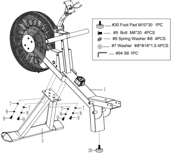
STEP 2:
Insert 2 Bolts (No. 32) through the Left & Right Pedals (No. 33 & No. 34) into the upper hole at position A of the Main Frame (No. 1). Tighten with Spanner (No. 96).
Insert 2 Bolts (No. 32) into the bottom hole at position B of the Main Frame (No. 1). Tighten with Spanner (No. 96).
NOTE: The Left & Right Pedals (No. 33 & No. 34) should rest on the bottom Bolts (No. 32) at position B. 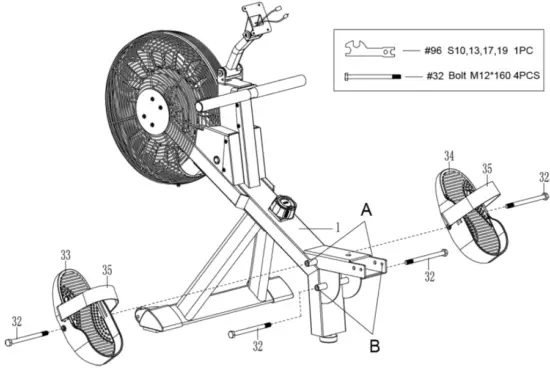
STEP 3:
Slide the Seat (No. 6) into the Sliding Rail (No. 2).
Attach 1 Limit Mat (No. 26) to the Sliding Rail (No. 2) using 2 Screws (No. 25). Tighten and secure with Spanner (No. 95). 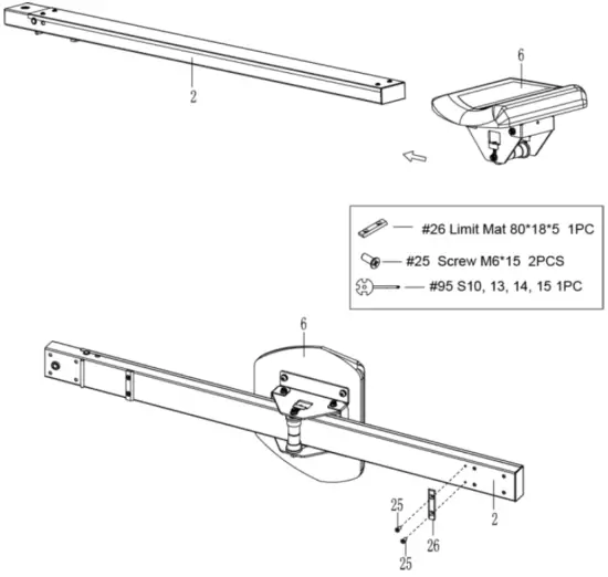
STEP 4:
Attach the Rear Stabilizer (No. 4) to the Sliding Rail (No. 2) using 4 Bolts (No. 9) and 4 Washers (No. 7). Tighten and secure with Wrench (No. 94). 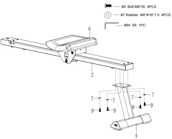
STEP 5:
Attach the Sliding Rail (No. 2) to the Main Frame (No. 1) using 1 Bolt (No. 38) and 1 Bolt (No. 37). Tighten and secure with Wrench (No. 93) and Wrench (No. 94).
Next, secure the Sliding Rail (No. 2) to the Main Frame (No. 1) using 1 Knob (No. 39) and 1 Washer (No. 40), then insert Pull Pin (No. 36). 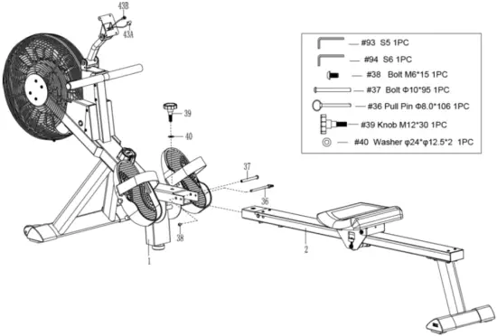
STEP 6:
Remove 6 Bolts (No. 51) from the back of the Meter (No. 50) with the Spanner (No. 95)
Attach the Tablet Holder (No. 99) to the Meter (No. 50) and screw with 2 Bolts (No. 51) that were removed. Tighten and secure with Spanner (No. 95).
Connect the Sensor Wire A (No. 43A) to the Meter Wire B (No. 50B) and connect the Sensor Wire B (No. 43B) to the Meter Wire A (No. 50A). Then insert them into the Meter Holder (No. 49).
Attach Meter (No. 50) to the Meter Holder (No. 49) with 4 Bolts (No. 51) that were removed. Tighten and secure with Spanner (No. 95). 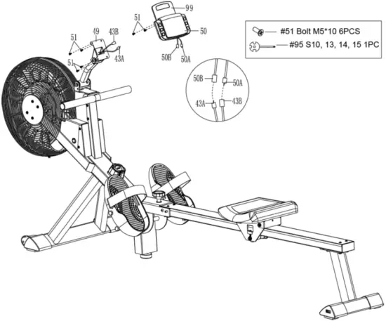
ADJUSTMENTS & USAGE GUIDE
CAUTION! Moving parts, such as the seat, can cut and crush. Keep hands clear of the sliding rail during use!
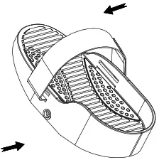 | PEDAL STRAP ADJUSTMENT |
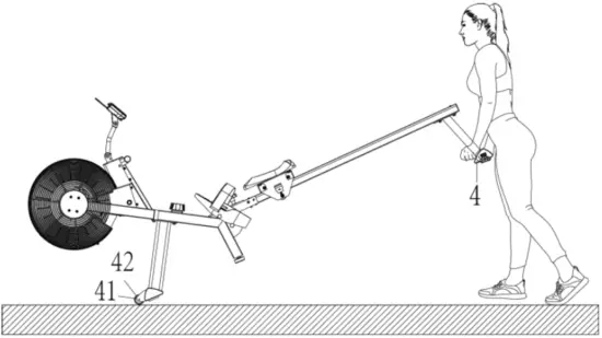 | MOVING THE ROWER To move the rower, lift the Rear Stabilizer (No. 4) up until the transportation wheels on the Left & Right End Caps (No. 41 & No. 42) touch the ground. With the transportation wheels on the ground, you can transport the rower to the desired location with ease. |
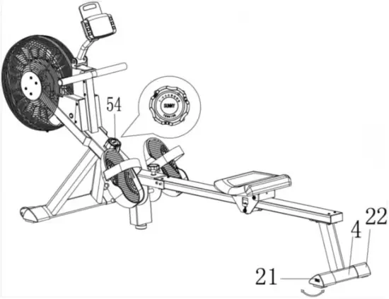 | ADJUSTING THE BALANCE AND RESISTANCE |
STORAGE GUIDE
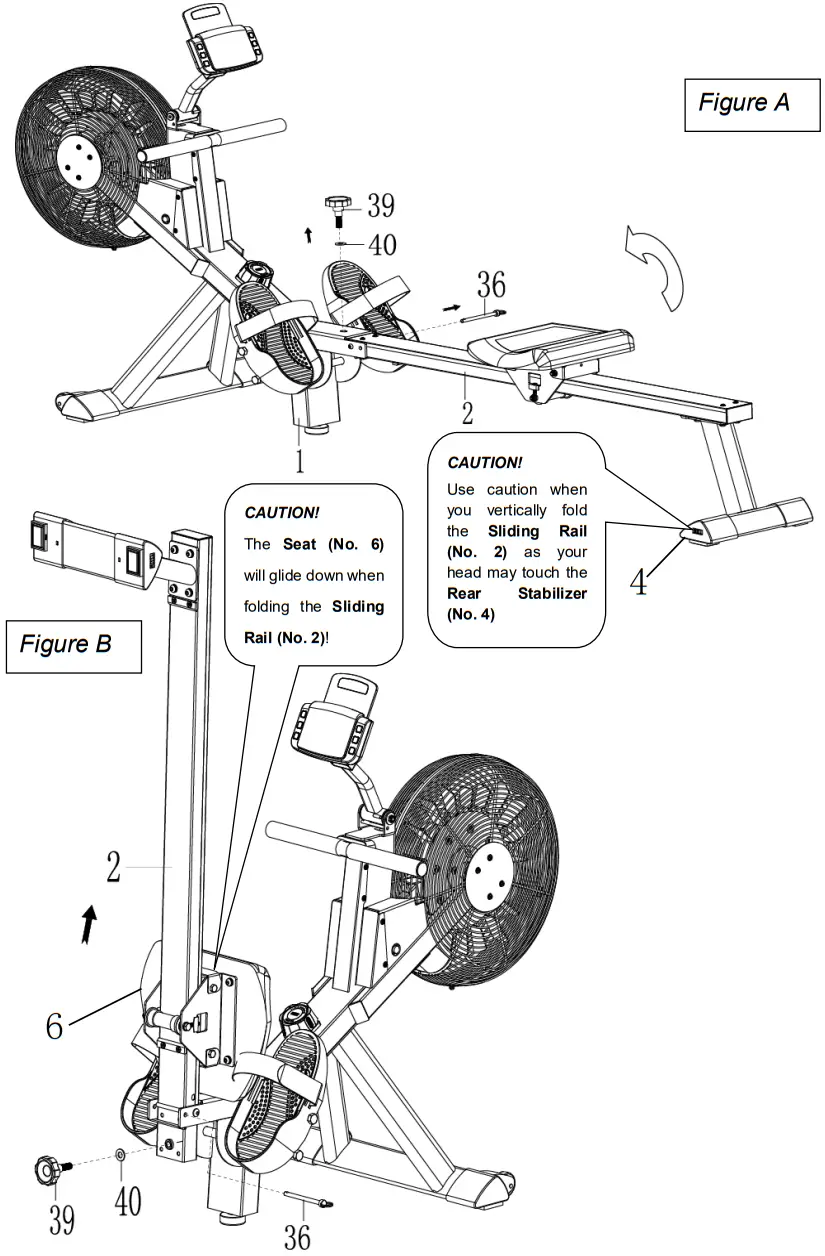
When not in use, you can save space by folding the Sliding Rail (No. 2).
Disassemble the Knob (No. 39) and Washer (No. 40) and pull out the Pull Pin (No. 36). Fold the Sliding Rail (No. 2) to a vertical angle (Figure A).
SAFETY NOTE: the Seat (No. 6) will glide down when folding the Sliding Rail (No. 2).
Reinsert Pull Pin (No. 36) into the hole on the Main Frame (No. 1), then tighten Knob (No. 39) and Washer (No. 40) to Main Frame (No. 1). (Figure B)
BATTERY INSTALLATION & REPLACEMENT
BATTERY INSTALLATION:
- Take out 2 AA batteries from the meter box.
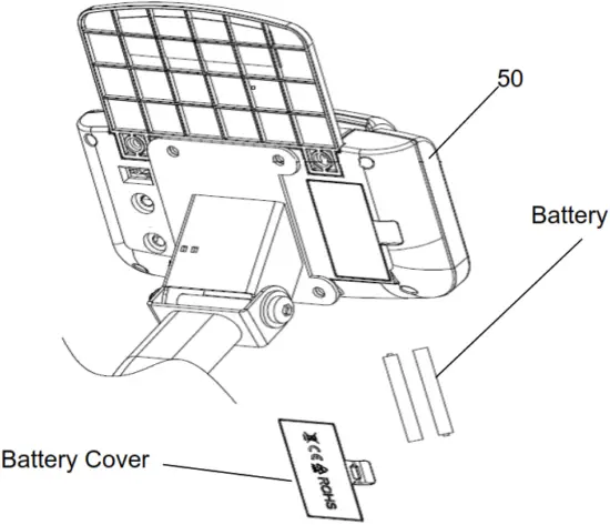
- Press the buckle of the battery cover on the back of the Meter (No. 50), then remove the battery cover.
- Install 2 AA batteries into the battery case on the back of the Meter (No. 50). Pay attention to the battery + and – poles before installing.
- Press the buckle of the battery cover, then put the battery cover back to the back of the Meter (No. 50).
The installation is complete!
BATTERY REPLACEMENT:
- Press the buckle of the battery cover on the back of the Meter (No. 50), then remove the battery cover.
- Remove the 2 old AA batteries in the battery case and install 2 new AA batteries into the battery case on the back of the Meter (No. 50). Pay attention to the battery + and – poles before installing.
- Press the buckle of the battery cover, then put the battery cover back to the back of the Meter (No. 50).
The replacement is complete!
NOTE: Always change both batteries at the same time. Do not mix battery types and do not mix old and new batteries. Dispose of batteries according to your state and regional guidelines.
EXERCISE METER
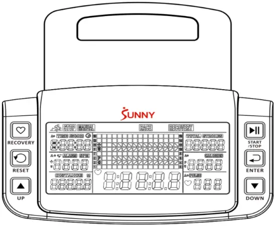
Our computerized exercise meter on the Sunny Rowing Machine allows the user to tailor a personalized workout by monitoring their progress. During a workout, the display console will alternately and repeatedly display the Time, Time/500M, SPM, Distance, Strokes, Total Strokes, Calories Burned, and Pulse.
BUTTONS
UP▲/DOWN ▼
Press these two buttons to scroll through the available selection.
To adjust the function values upward and downward.
ENTER:
To confirm your selection.
During training, press this button to scan each display function.
START /STOP:
To start and stop your selected workout program.
RESET:
To return the meter back to the main menu.
Press and hold for 3 seconds to reset values.
RECOVERY:
To activate the RECOVERY PROGRAM that will automatically evaluate your fitness immediately after a workout
FUNCTIONS
TIME: Set target time (1 min ~ 99 min) by pressing UP and DOWN buttons, in 1-minute increments.
TIME/500M: Your average 500M time is automatically displayed.
SPM: Strokes per minute.
DISTANCE: Preset target distance (100 ~ 99900 meters) by pressing UP and DOWN buttons, in 100 meters increments.
STROKES: Set target stroke (10 ~ 9990 strokes) by pressing UP and DOWN buttons, in 10 strokes increments.
TOTAL STROKES: Accumulates total strokes from 0 to 9999.
CALORIES: Set target calories (10 ~ 9990 Cal) by pressing UP or DOWN buttons, in 10 Cal increments.
HRC/PULSE: Displays heart rate.
In Manual Mode, set the target pulse by pressing UP and DOWN buttons (30 ~ 240 BPM), in 1 BPM increments. HRC will display at the top of the meter. The meter will display your heart rate during training. When it reaches the target value, PULSE will flash, and the meter will beep until it is changed to another mode or you remove the chest strap. The pulse measurement function only works with 5.3 KHz chest strap heart rate monitors.
CALENDAR: The meter will display year, month, and day when the meter is in sleep mode.
TEMPERATURE: The meter will display the current room temperature when the meter is in sleep mode.
CLOCK: The meter will display the current time when the meter is in sleep mode.
Note: Chest Strap Heart Rate Monitor is not included.
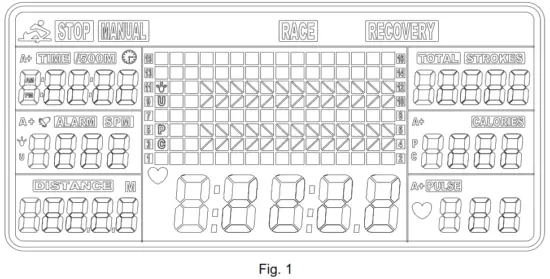
OPERATION
- Install 2 PCS AA batteries (included) and the meter will beep for 2 seconds (Fig.1).
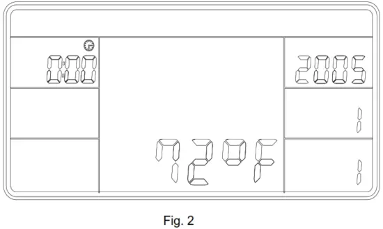
Then, the meter enters into the CLOCK & CALENDAR MODE (Fig.2).

- The CLOCK will flash. Press the UP button to set the hour. Press ENTER to confirm.
Press UP to set the minutes. Press ENTER to confirm. Continue to press the UP button to set the YEAR (in the STROKES window); MONTH (in the CALORIES window); DAY (in the PULSE window). Press ENTER to confirm when it is set.
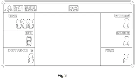
After you confirm it, the ALARM will beep. Press ENTER to skip setting up the alarm. To set up the alarm, press the UP button to turn on ALARM. An arrow will appear next to ALARM. Press ENTER. The CLOCK window will flash. Press the UP or DOWN buttons to set the alarm time. Press ENTER to confirm, Meter will go into the SPORT screen (Fig. 3).
- When you enter the SPORT screen, MANUAL and RACE will flash. Press UP or DOWN to select MANUAL or RACE. Press ENTER to confirm your selection.
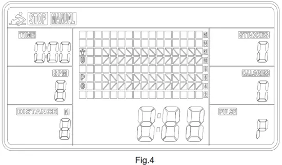
- MANUAL (Fig.4): There are 2 options in MANUAL mode.
a. The meter can be set to count down. When you select MANUAL, the value of TIME will start to flash. Press UP to set the value of TIME to count down. Press ENTER to confirm it. Press ENTER to skip setting up the time COUNTDOWN and go to the next function. You can set the values for DISTANCE, STROKES, CALORIES, or PULSE. (Note: You can only set the value for one function to countdown. For example, if you have set the target value for TIME, then DISTANCE can’t be set.)
Press the START button to start and the STOP icon will disappear. When the countdown reaches zero or if you press the STOP button, the meter will stop and display the average value.
b. The meter counts the value of your workout. Press START to start.
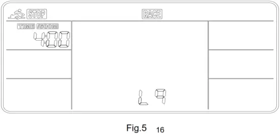
- RACE (Fig.5):
Select RACE mode and L9 will flash. The TIME /500M will display at 4:00. Then, press UP or DOWN to select L1~L15. Press ENTER to confirm. Then, you can set the distance of the race (500 ~10000M) while the value of DISTANCE is blinking. Press ENTER and the picture of the race will display on the screen.
The TIME/500M of the programs are as follows:L1 L2 L3 L4 L5 L6 L7 L8 L9 L10 L11 L12 L13 L14 L15 8:00 7:30 7:00 6:30 6:00 5:30 5:00 4:30 4:00 3:30 3:00 2:30 2:00 1:30 1:00  a. Press START button to start and the STOP icon will disappear. USER and PC will display in the matrix (Fig.6). The meter will stop when either the user or meter has reached the race distance that was set. Then, the matrix displays “PCWIN” or “USERWIN” (Fig.7).
  b. When the race is over, you can press START to start a race once again. Press RESET to leave the RACE screen.
 - RECOVERY:
This meter works with a 5.3 KHz chest strap heart rate monitor (not included). After exercising for a period of time, keep wearing the chest strap monitor and press the RECOVERY button. All function displays will stop except “TIME” starts counting down from 00:60 to 00:00.
The screen will display your heart rate recovery status with the F1, F2….to F6.F1 is outstanding. F6 is poor. Users may keep exercising to improve their heart rate recovery status. (Press the RECOVERY button again to return the main display.)
 a. Press START button to start and the STOP icon will disappear. USER and PC will display in the matrix (Fig.6). The meter will stop when either the user or meter has reached the race distance that was set. Then, the matrix displays “PCWIN” or “USERWIN” (Fig.7).
 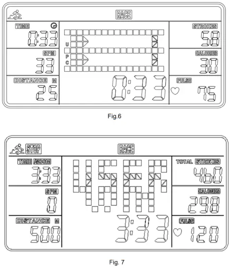 b. When the race is over, you can press START to start a race once again. Press RESET to leave the RACE screen.
ALARM
The alarm only works while the meter is in sleep mode. The alarm will not sound during exercise. Press and hold RESET to go to the clock screen to set up ALARM.
SLEEP MODE
The meter will go into sleep mode after about 4 minutes of inactivity.
BATTERY
This meter uses 2 AA batteries, which are included. Changing the batteries will reset all values. If there is a problem with the display, try to change the batteries first. When changing the batteries, change both. Do not mix battery types. Do not mix old and new batteries. Dispose of batteries according to your state and regional guidelines.
CONNECT WITH US
FOR FITNESS ARTICLES, VIDEOS & WORKOUTS
 https://sunnyhealthfitness.com/pages/sign-up
![]()
![]() @SUNNYHEALTHANDFITNESS
@SUNNYHEALTHANDFITNESS![]() @SUNNYHEALTHFITNESS
@SUNNYHEALTHFITNESS![]() ©SUNNYHEALTHFIT
©SUNNYHEALTHFIT![]() /ISUNNYHEALTHFITNESS
/ISUNNYHEALTHFITNESS![]() /SUNNYHEALTHANDFITNESS
/SUNNYHEALTHANDFITNESS
WWW.SUNNYHEALTHFITNESS.COM


