VigilLink VLMX-0404E 4X4 HDMI 2.0 Matrix with Output 4K to 1080p Downscaling and Display Control User Manual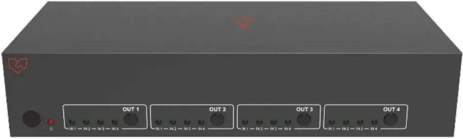
Introduction
This high-performance HDMI Matrix Switcher can switch any of these four HDMI 2.0 sources to four HDMI 2.0 displays. Each input and output supports up to 4K60 444 resolution and HDCP 2.2. The outputs can be individually scaled for 1080p. De-embedded audio as analog L/R and coaxial is available for both outputs. The ARC function can return display device audio to coaxial port output only. Advanced EDID management is supported with its 18Gbps bandwidth and additional features with the latest HDMI standards. This switcher can be controlled from the front panel, RS-232, IR remote, or TCP/IP.
Features
- HDMI 2.0, HDCP 2.2 / HDCP 1.4, and DVI 1.0 compliant
- Four 18G HDMI 2.0 video inputs support up to 4K60 444 resolution
- Four 18G HDMI 2.0 video outputs support up to 4K60 444 resolution
- Four outputs can be individually scaled for 4K→1080p
- De-embedded audio to analog L/R and Coaxial ports output
- ARC audio returns to the coaxial port’s output only
- Built-in Web GUI for TCP/IP control
- Advanced EDID management supported
- Four methods of control: Front panel, RS-232, IR remote, and TCP/IP
- Compact design for easy and flexible installation
Package Contents
| Qty | Item |
| 1 | 4×4 HDMI 2.0 18Gbps Matrix Switcher |
| 1 | 12V/2.5A Locking Power Adapter |
| 1 | IR Remote |
| 2 | Mounting Ears |
| 1 | 38KHz IR Receiver Cable (1.5 meters) |
| 1 | 3-pin Phoenix Connector |
| 1 | User Manual |
Specifications
| Technical | |
| HDMI Compliance | HDMI 2.0 |
| HDCP Compliance | HDCP 2.2 and HDCP 1.4 |
| Video Bandwidth | 18 Gbps |
| Video Resolution | 4K2K 50/60Hz 4:4:44K2K 50/60Hz 4:2:04K2K 30Hz 4:4:41080p, 1080i, 720p, 720i, 480p, 480iAll HDMI 3D TV formatsAll PC resolutions, including 1920 x 1200 |
| Output Scaling | 4K to 1080p |
| 3D Support | Yes |
| Color Space | RGB, YCbCr4:4:4,YCbCr4:2:2, YCbCr 4:2:0 |
| Color Depth | 8-bit, 10-bit, 12-bit [1080P, 4K30Hz, 4K60Hz (YCbCr 4:2:0)]8-bit [4K60Hz (YCbCr 4:4:4)] |
| HDMI Audio Formats | PCM2.0/5.1/7.1CH, Dolby Digital/Plus/EX, Dolby True HD, DTS, DTS-EX, DTS-96/24, DTS High Res, DTS-HD MasterAudio, DSD |
| Coaxial Audio Formats | PCM2.0, Dolby Digital / Plus, DTS 2.0/5.1 |
| L/R Audio Formats | PCM2.0CH |
| HDR Support | HDR10, HDR10+. Dolby Vision, HLG |
| ESD Protection | Human-body Model: ±8kV (Air-gap discharge),±4kV (Contact discharge) |
| Connections | |
| Input Ports | 4×HDMI Type A [19-pin female] |
| Output Ports | 4×HDMI Type A [19-pin female]4×L/R audio out [3.5mm Stereo Mini-jack] 4×COAX audio out [RCA] |
| Control ports | 1x TCP/IP [RJ45]1x RS-232[3-pin phoenix connector] 1x IR EXT [3.5mm Stereo Mini-jack] |
| Mechanical | |||
| Housing | Metal Enclosure | ||
| Color | Black | ||
| Dimensions | 220mm (W)×105mm (D)×44mm (H) | ||
| Weight | 792g | ||
| Power Supply | Input: AC100~240V 50/60HzOutput: DC12V/2.5A (Locking connector) | ||
| Power Consumption | 10W (max), 1.56W (Standby) | ||
| Operating Temperature | 0°C ~ 40°C / 32°F ~ 104°F | ||
| Storage Temperature | -20°C ~ 60°C / -4°F ~ 140°F | ||
| Relative Humidity | 20~90% RH (Non-Condensation) | ||
| Resolution / Cable Length | 4K60 –Feet / Meters | 4K30 –Feet / Meters | 1080P60 –Feet / Meters |
| HDMI IN / OUT | 10ft / 3M | 30ft / 10M | 42ft / 15M |
| The use of the “Premium High-Speed HDMI” cable is highly recommended. | |||
Operation Controls and Functions
Front Panel
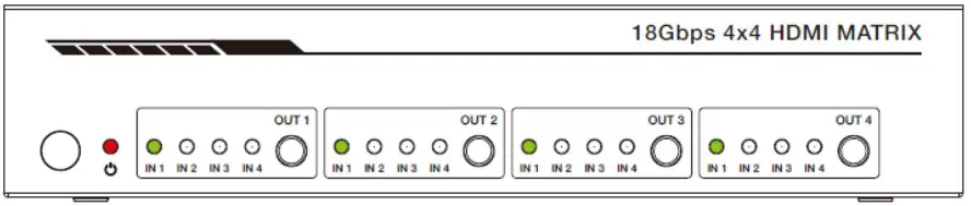
| Name | Function description |
| IR Sensor | IR input for remote control of the switcher. |
| POWER LED | Red LED indicates that the unit is powered. |
| OUT 1 / OUT 2 /OUT 3 / OUT 4 Button | Press to select the desired input. |
| IN 1 IN2 / IN3 / IN4 LED | Green LED indicates when the input is selected for therespective output. |
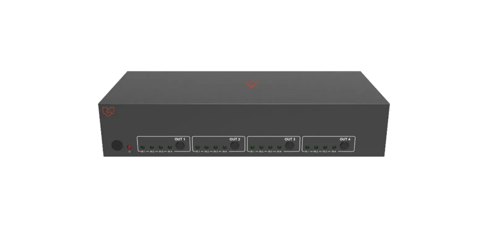
Rear Panel
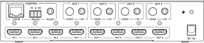
| Name | Function description |
| TCP/IP (RJ45) | Control port for TCP/IP control or accessing the built-in Web GUI. |
| RS-232 | 3-pin pluggable connector for RS-232 control of the Switcher. |
| IR EXT | IR eye input for IR control of the Switcher. |
| Coaxial Audio OUT 1/ OUT 2 / OUT 3 / OUT 4 | RCA connector for coaxial audio output from HDMI OUT 1/ OUT 2 / OUT 3 / OUT 4. |
| L/R Audio OUT 1/ OUT 2 / OUT 3 / OUT 4 | 3.5mm Mini-jack connector for stereo audio output from HDMI OUT 1 / OUT 2 / OUT 3 / OUT 4. |
| Earthing Point | Screw terminal for earthing the Switcher. |
| HDMI Input 1 to 4 | HDMI Source inputs 1 to 4. |
| HDMI Output 1 to 4 | HDMI outputs for displays 1 to 4. |
| DC 12V IN | DC 12V input for 12V 2.5A PSU. |
Connecting to the Switcher
- Connect the desired HDMI input sources.
- Connect the desired HDMI display devices.
- Connect any CONTROL inputs that may be required: TCP/IP, RS-232, or IR IN.
- Connect any audio devices to either the Coaxial or L/R outputs.
- Connect the 12V DC PSU.
Using the Switcher
Power LED and Standby Mode
The Power LED provides the following indications:
| Color | Description |
| Red | The Switcher is active and fully controllable |
| Off | The Switcher is in standby mode; this state can be changed using API commands, IR Remote, or the Web GUI interface. |
Selecting Inputs
Manual Selection of the inputs is done by briefly pressing the OUT 1 / OUT 2 / OUT 3 / OUT 4 button repeatedly for that channel until the desired input is selected.
IR Remote
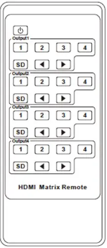
| Power on the Switcher or set it to standby mode. | |
| Output 1 (Output 2 / 3 / 4) | |
| 1/2/3/4 | Select the desired input source to Output 1 port output, the corresponding green LED on the front panel illuminates. |
| SD | Switch downscale or bypass mode to the Output 1 port output. |
| Select the last or next the desired input source to Output 1 port output, the corresponding greenLED on the front panel illuminates. | |
Using the Built-In Web GUI Interface
The Switcher has a built-in Web interface to provide a means of controlling or configuring various settings. There are six pages available, each of which will be outlined in detail in the following sections:
The six pages are:
- Status – Display information about the firmware and IP setting.
- Video – Switch the desired input source to output and set the preset.
- Input – Display information about the input signal and EDID setting.
- Output – Display information about the output signal and scaler option.
- Network – Allow basic network setting management and login options.
- System – Panel lock, beep, serial baud rate setting, and firmware update
Note that these six pages are only accessible in Admin mode; only the Status and Video pages are available when User mode is used.
To access the Web interface, enter the switcher’s IP address into any web browser’s address bar. The default IP address is 192.168.1.100. Please see the following operation method. Note that if the switcher’s IP address is unknown, use the RS-232 command given in the Network Setting section “r ip addr!” to discover the current IP address or set the switcher to factory default status and IP address restores to default 192.168.1.100.
Step 1: The TCP/IP port on the rear panel has directly connected a PC with a UTP cable.
Step 2: Set your PC IP address to the same network segment with Switcher; for instance, set your PC IP address to 192.168.1.200 and Subnet mask to 255.255.255.0.
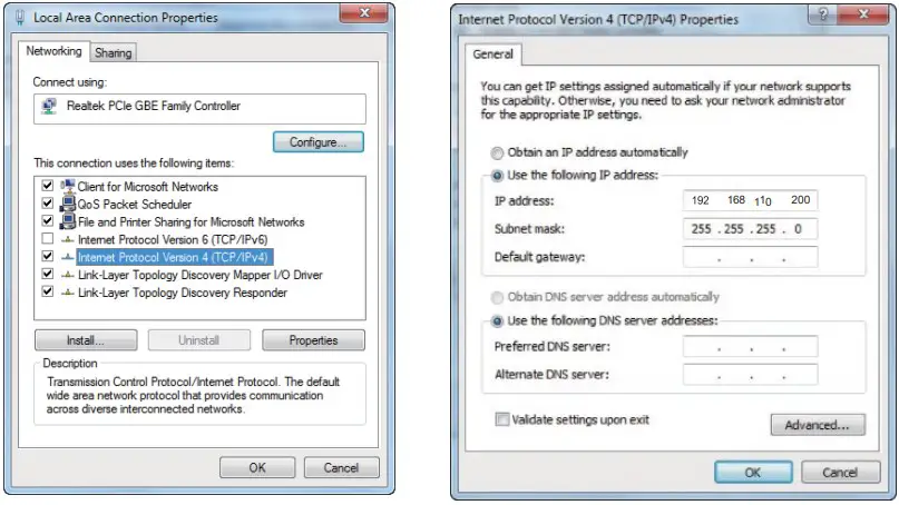
Step 3: Enter the Switcher’s IP address into your browser on the PC to enter
the Web GUI
After entering the IP address, the following log-in screen will appear:

Select the Username from the list and enter the password. The default passwords are:
Username User Admin
Password user admin
After entering the log-in details, click the LOGIN button, and the followingStatus page will appear.
Status page
The Status page provides basic information about the product Model name, the installed firmware version, and the network setting. This page is visible in both User and Admin modes.
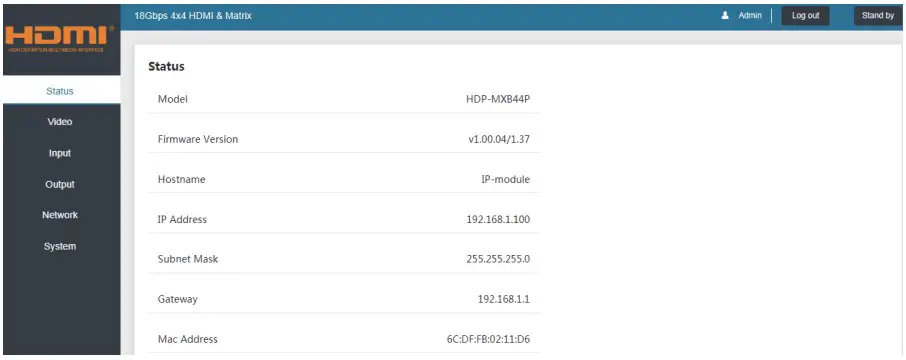
The buttons at the top right of the web interface are always available and provide the following function:
- The Log-out button will disconnect the current user from displaying thelog-in screen.
- The Power on button changes the power status of the Switcher between On and Stand-by mode.
Video page
The Video page allows the input source selection and sets the presets.
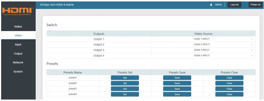
For this preset setting, you first need to select the desired input source to four output ports. Then click the Save button to save the setting. When you click the line Set button, this preset you have saved will be used. The Clear button will clear the preset. There are four presets setting available.
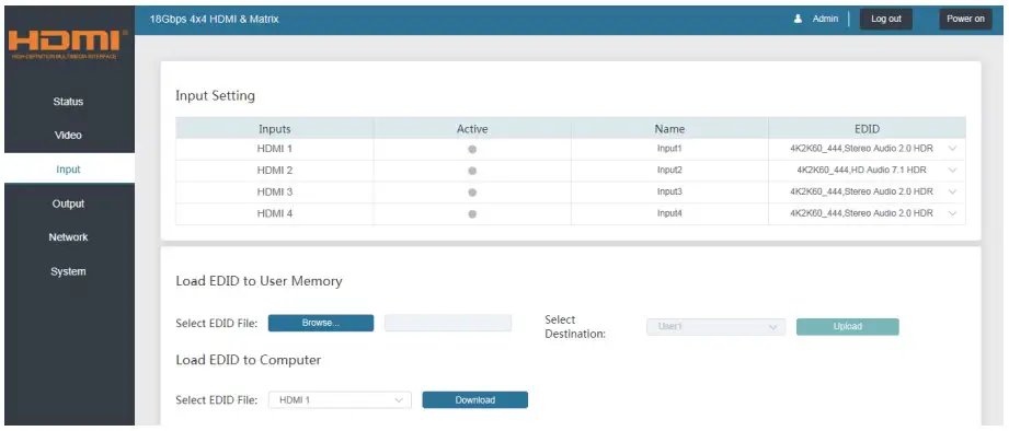
Input page
The Input page provides information about which inputs are connected and have a signal. The inputs can be given more meaningful names if desired. The EDID column provides a list of EDID options for each input. The following EDID options are available in any of the EDID drop-down lists
- 1080P, Stereo Audio 2.0
- 1080P, Dolby/DTS 5.1
- 1080P, HD Audio 7.1
- 1080I, Stereo Audio 2.0
- 1080I, Dolby/DTS 5.1
- 1080I, HD Audio 7.1
- 3D, Stereo Audio 2.0
- 3D, Dolby/DTS 5.1
- 3D, HD Audio 7.1
- 4K2K30Hz_444 Stereo Audio 2.0
- 4K2K30Hz_444 Dolby/DTS 5.1
- 4K2K30Hz_444 HD Audio 7.1
- 4K2K60Hz_420 Stereo Audio 2.0
- 4K2K60Hz_420 Dolby/DTS 5.1
- 4K2K60Hz_420 HD Audio 7.1
- 4K2K60Hz_444 Stereo Audio 2.0
- 4K2K60Hz_444 Dolby/DTS 5.1
- 4K2K60Hz_444 HD Audio 7.1
- 4K2K60Hz_444 Stereo Audio 2.0 HDR
- 4K2K60Hz_444 Dolby/DTS 5.1 HDR
- 4K2K60Hz_444 HD Audio 7.1 HDR
- USER_1
- USER_2
- COPY_FROM_TX_1
- COPY_FROM_TX_2
- COPY_FROM_TX_3
- COPY_FROM_TX_4
This page also provides a means of sending a binary EDID file to either User 1 or User 2 EDID memories:
- Select the binary EDID file on your PC by clicking the Browse button.
- Select either User 1 or User 2 from the drop-down list.
- Click the Upload button.
The EDID data from any input or from the User 1 and User 2 locations can be read and stored on your PC.
Output page
The outputs can also be assigned meaningful names if desired. The Output page provides information about the signal status of the outputs.
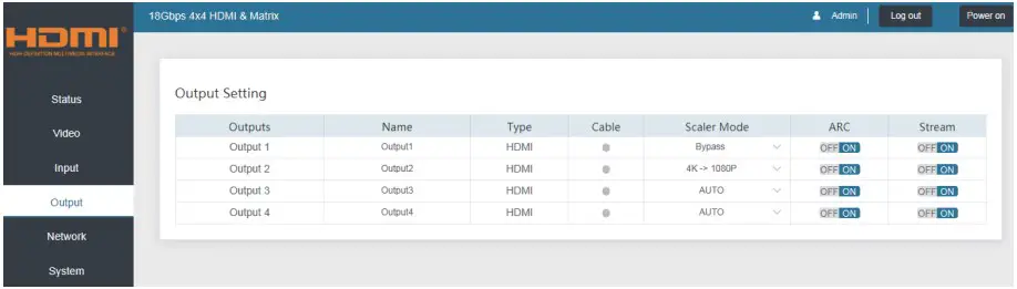
The Scaler mode menu provides the following options:
| Bypass | Follow the input source. (Pass-through) |
| 4K→1080P | Downscale to 1080p, if needed. |
| AUTO | Scaler to match the display requirements. |
The ARC buttons enable or disable the display device audio to the coaxial audio outputs. If the ARC function enables, the L/R audio port will have novoice output simultaneously. The Stream buttons enable or disable the output signal for the respective output.
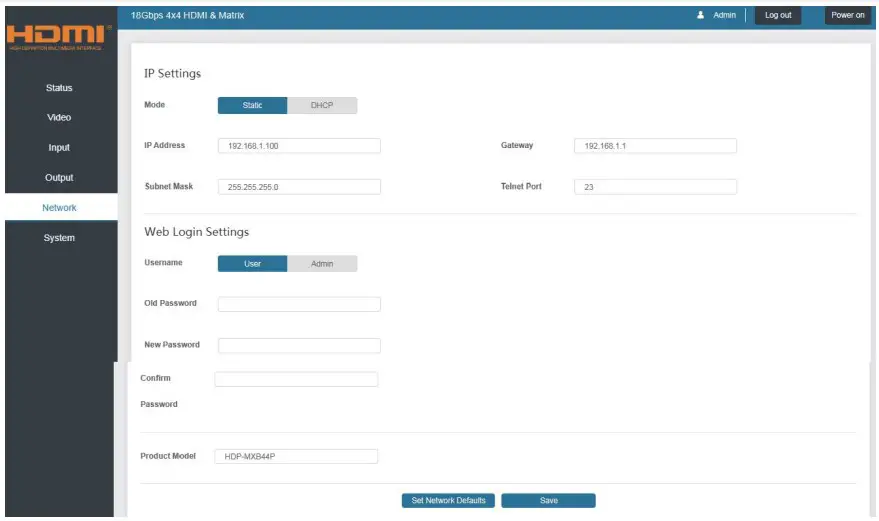
Network page
The Network page allows the configuration of the network settings. Note that the IP address boxes are only accessible when the Mode button is set to Static. The log-in passwords can be changed on this page. Note that any changes to this page will require the new details into the web browser and/or the log-in screen.
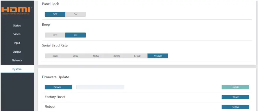
System page
The system page allows setting the panel lock and beeping on/off to controlthe RS-232 port baud rate. This page is also used to install the new firmware update, restore the factorydefault settings and reboot the Switcher
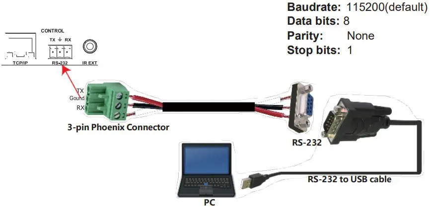
API control command
RS-232 can also control the Switcher. Connect a PC using a serial cable and open any Serial Command tool on the PC such as Comm Operator, Docklight or hercules, etc. to send a command for controllingthe Switcher. Please see the following connection diagram.
Important:
- All messages sent to the Switcher must be terminated with an exclamation mark (!). Any carriage return present after the command’s end will be ignored.
- All spaces shown in the commands are required.
- A CR/LF sequence terminates all response messages.
- When the same command requests all four inputs, the responsewill report each input on a separate line.
- When the same command requests four outputs, the responsewill report each output on a separate line
The ASCII list of the product is shown below.
| ASCII Command | ||
| Serial port protocol: Baud rate:115200 (default), Data bits: 8bit, Stop bits:1, Check bit: None TCP/IP protocol port: 8000The x, y, z, and XXX are parameters. | ||
| RS-232Command | Function description | Feedback |
| Power | ||
| s power z! | power on/off the device,z=0~1(z=0 power off, z=1 power on) | power onSystem Initializing… Initialization Finished! power off |
| r power! | get current power state | power on /power off |
| s reboot! | reboot the device | Reboot…System Initializing… Initialization Finished! |
| SYSTEM Setup | ||
| help! | Lists all commands | |
| r type! | Get device model | HDP-MXB44P |
r status! | Get device current status | Get the unit all status: power, beep, lock, in/out connection, video/audio crosspoint, edid, scaler,hdcp, network status |
| r fw version! | Get Firmware version | MCU FW version x.xx.xx |
| r link in x! | Get the connection status of the x input port, x=0~4(0=all) | HDMI IN1: connect |
| r link out y! | Get the connection status of the y output port, y=0~4(0=all) | HDMI OUT1: connect |
| s reset! | Reset to factory defaults | Reset to factory defaults System Initializing…Initialization Finished! |
| s beep z! | Enable/Disable buzzer function,z=0~1(z=0 beep off, z=1 beep on) | beep on / beep off |
| r beep! | Get buzzer state | beep on / beep off |
| s lock z! | Lock/Unlock front panel button,z=0~1(z=0 lock off,z=1 lock on) | panel button lock on panel button lock off |
| r lock! | Get panel button lock state | panel button lock on/off |
| s save preset z! | Save switch state between all output port and theinput port to preset z,z=1~8 | save to preset 1 |
| s recall preset z! | Call saved preset z scenarios,z=1~8 | recall from preset 1 |
| s clear preset z! | Clear stored preset z scenarios,z=1~8 | clear preset 1 |
| r preset z! | Get preset z infomation, z=1~8 | video/audio crosspoint |
| s baud rate xxx! | Set the serial port baud rate of RS02 module, z=(115200,57600,38400,19200,9600,4800) | Baudrate:115200 |
| r baud rate! | Get the serial port baud rate of RS02 module | Baudrate:115200 |
| s id z! | Set the control ID of the product, z=000~999 | id 888 |
| Output Setting | ||
| s in x av out y! | Set input x to output y,x=1~4,y=0~4(0=all) | input 1 -> output 2 |
| r av out y! | Get output y signal status y=0~4(0=all) | input 1 -> output 1input 2 -> output 2……input 4 -> output 4 |
| s out y stream z! | Set output y stream on/off, y=0~4(0=all) z=0~1 (0:disable,1:enable) | Enable out 1 stream Disable out 1 stream |
| r out y stream! | Get output y stream status, y=0~4(0=all) | Enable out 1 stream |
| s hdmi y scaler z! | Set hdmi output y port output scaler mode, y=0~4 (0=all), z=1~3(1=bypass,2=4K->1080p,3=Auto) | hdmi 1 set to bypass mode |
| r hdmi y scaler ! | Get hdmi output y port output mode y=0~4(0=all) | hdmi 1 set to bypass mode |
| s hdmi y hdcp z! | Set hdmi output y port hdcp status y=0~4(0=all) z=0~1(1=active,0=off) | hdmi 1 hdcp active |
| r hdmi y hdcp! | Get HDCP status of HDMI out y, y=0~4(0=all) | hdmi 1 hdcp active |
| Audio Setting | ||
| s hdmi y arc z! | Turn on/off arc of HDMI output y ,y=0~4(0=all) z=0~1(z=0,off,z=1 on) | hdmi output 1 arc on hdmi output 1 arc off |
| r hdmi y arc! | Get the arc state of HDMI output y,y=0~4(0=all) | hdmi out1 arc on |
| EDID Setting | ||
r edid in x! | Get EDID status of the input x, x=0~4(0=all inputs) | IN1 EDID: 4K2K60_444,Stereo Audio 2.0IN2 EDID: 4K2K60_444,Stereo Audio 2.0IN3 EDID: 4K2K60_444,Stereo Audio 2.0IN4 EDID: 4K2K60_444,Stereo Audio 2.0 |
| r edid data hdmi y! | Get the EDID data of the hdmi output y port, y=1~4 | EDID : 00 FF FF FF FF FFFF 00 ……… |
s edid in x from z! | Set input x EDID from default EDID z, x=0~4(0=all),z=1~231、1080p,Stereo Audio 2.02、1080p,Dolby/DTS 5.13、1080p,HD Audio 7.14、1080i,Stereo Audio 2.05、1080i,Dolby/DTS 5.16、1080i,HD Audio 7.17、3D,Stereo Audio 2.08、3D,Dolby/DTS 5.19、3D,HD Audio 7.110、4K2K30_444,Stereo Audio 2.011、4K2K30_444,Dolby/DTS 5.112、4K2K30_444,HD Audio 7.113、4K2K60_420,Stereo Audio 2.014、4K2K60_420,Dolby/DTS 5.115、4K2K60_420,HD Audio 7.116、4K2K60_444,Stereo Audio 2.017、4K2K60_444,Dolby/DTS 5.118、4K2K60_444,HD Audio 7.119、4K2K60_444,Stereo Audio 2.0 HDR20、4K2K60_444,Dolby/DTS 5.1 HDR21、4K2K60_444,HD Audio 7.1 HDR22、USER123、USER224 、Copy_From_Hdmi_Tx_125 、Copy_From_Hdmi_Tx_226 、Copy_From_Hdmi_Tx_3 27、Copy_From_Hdmi_Tx_4 | IN1 EDID:1080p,Stereo Audio 2.0 |
| Network setting | ||
r ipconfig! | Get the Current IP Configauration | IP Mode: Static, IP: 192.168.1.72Subnet Mask: 255.255.255.0,Gateway: 192.168.1.1Mac address: 00:1C:91:03:80:01 TCP/IP port=8000, telnet port=10 |
| r mac addr! | Get network MAC address | Mac address: 00:1C:91:03:80:01 |
| s ip mode z! | Set network IP mode to static IP or DHCP, z=0~1 (z=0 Static, z=1 DHCP ) | Set IP mode:Static. Please use “s net reboot!”command or repower device to apply new config! |
| r ip mode! | Get network IP mode | IP mode: Static |
| s ip addr xxx.xxx. xxx.xxx! | Set network IP address | Set IP address:192.168.1.100 Please use “s net reboot!” command or repower device to apply new config! DHCP on, Device can’t config static address, set DHCP off first. |
| r ip addr! | Get network IP address | IP address:192.168.1.100 |
| s subnet xxx.xxx. xxx.xxx! | Set network subnet mask | Set subnet Mask:255.255.255.0 Please use “s net reboot!” command or repower device to apply new config!DHCP on, Device can’t config subnet mask, set DHCP off first. |
| r subnet! | Get network subnet mask | Subnet Mask:255.255.255.0 |
| s gateway xxx.xxx. xxx.xxx! | Set network gateway | Set gateway:192.168.1.1 Please use “s net reboot!” command or repower device to apply new config! DHCP on, Device can’t config gateway, set DHCP off first. |
| r gateway! | Get network gateway | Gateway:192.168.1.1 |
| s tcp/ip port x! | Set network TCP/IP port (x=1~65535) | Set tcp/ip port:8000 |
| r tcp/ip port! | Get network TCP/IP port | tcp/ip port:8000 |
| s telnet port x! | Set network telnet port(x=1~65535) | Set telnet port:23 |
| r telnet port! | Get network telnet port | telnet port:23 |
s net reboot! | Reboot network modules | Network reboot… IP Mode: Static IP: 192.168.1.72Subnet Mask: 255.255.255.0Gateway: 192.168.1.1Mac address: 00:1C:91:03:80:01 TCP/IP port=8000telnet port=10 |
Note that you can send the ‘RS232 command’ to control the Switcher via the Serial Command tool. The ‘Function description’ explains the function of the command. The “Feedback” displays whether the command sends success or not and feedback on the information you need
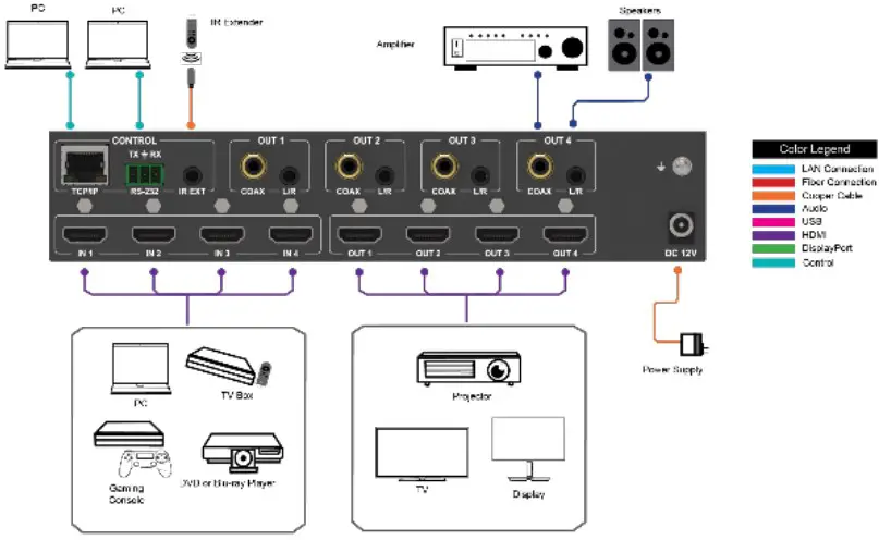
Application Example