Fanvil i56A Indoor Station Installation Guide
Package Contents
- Indoor Station

- Quick Installation Guide

- Wall-mount Bracket

- Desktop Bracket (Optional)

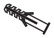
- 10 pin Cable*1

- 6 pin Cable*1

- 4 pin Cable*1

- TA4*30mm Screw*2

- PM4*16mm Screw*2

- Screw fixing seat*2


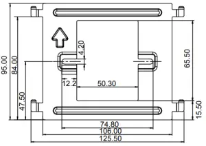
Physical specification
Dimension | 259 x 193 x 20 (mm) |
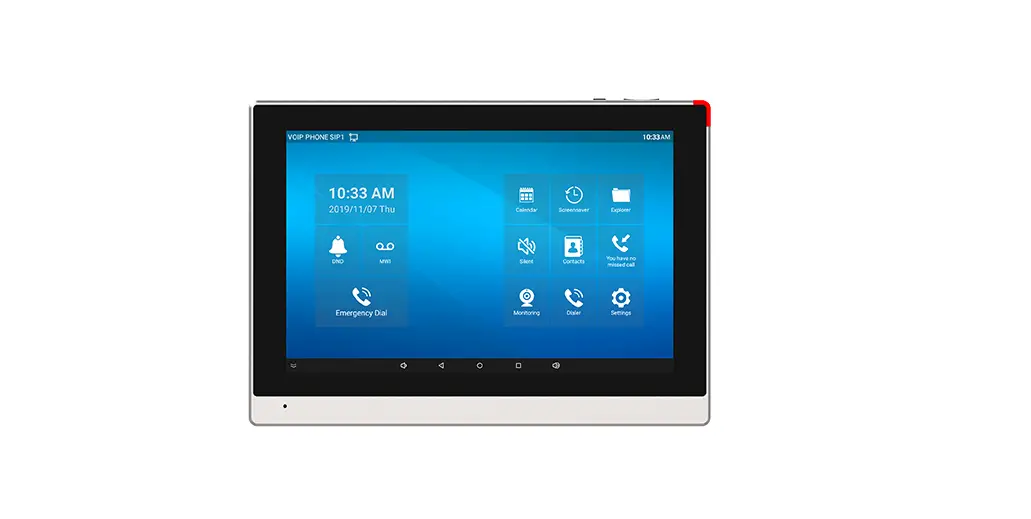
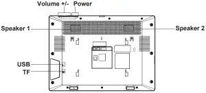
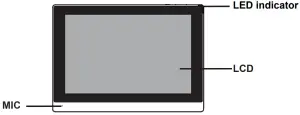
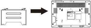
- Panel


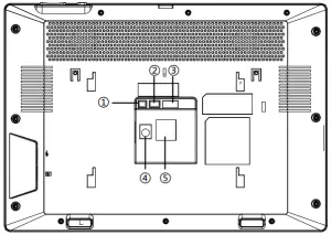
- Interface description
There are some interfaces on the back of the device for connecting power supply, alarms etc. The connections are as follows:
No. Description Interface 1
1 set of RS485 interface: can be connected to card reader, sensor etc. 
2
2 sets of short-circuit output interfaces: corresponding to the short-circuit input interface, login device webpage settings, can be connected to electric locks, alarms etc. 
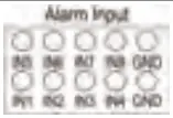
3
8 sets of alarm input interfaces: input devices for connecting switches, infrared sensor, door sensor, vibration sensors etc. 
4
Power interface:12V/1A input. 
5
Ethernet interface: standard RJ45 interface, 10/100M adaptive, it is recommended to use CAT5 or CAT5E network cable. 
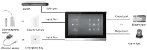
- External device connection diagram


Installation(two models)
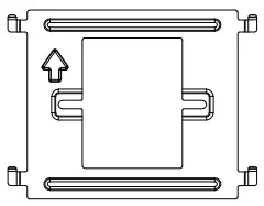
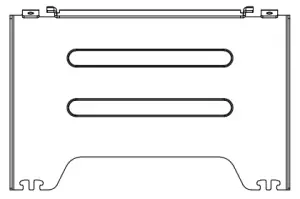
- Wall bracket

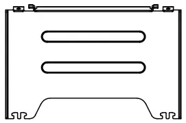
- Desktop bracket

Model 1. Wall-mounted Installation
Step 1. Install wall bracket
Without 86 embedded box in the wall
- A. According to the position of the cable in the wall, dig out a square hole (height*width*depth=65.5*50.5*50mm) that can accommodate all cables.
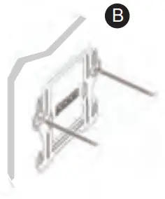
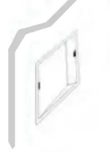
- B. Align the square hole of the wall bracket with the hole digged out before, then mark the two fixation holes through bracket on the wall.
- C. Take down the bracket, using an electric drill to make the two fixation holes on the wall ,then insert the two screw fixing seats provided.
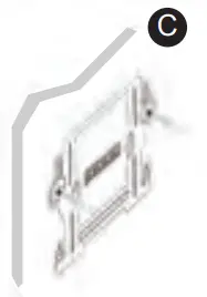
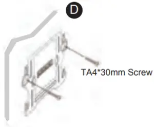
- D. Fix the wall bracket on the wall with two TA4*30 screws.


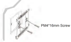
With 86 embedded box in the wall
- A. Make sure all cables in the embedded box .
- B. Fix the wall bracket on the 86 embedded box with two PM4*16mm screws.


Step 2. Connect peripherals
- A. If you need to connect other input and output devices, please connect to the host through the cable.
Step 3. Power on the device. If it is working properly, align the slot on the rear side of the panel with the pin on the wall bracket and slide the host down to complete the installation.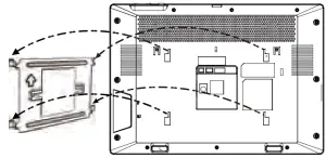
Model 2. Desktop Installation
Align the slot on the rear side of the panel with the pin on the desktop bracket and slide the bracket up to complete the installation.
Searching IP address
There are two methods as shown below to search the device. The default WAN mode is DHCP.
- Method 1:
After booting, click “Settings”—“Common” to query. - Method 2:
After booting, pull down the notification bar to query.
IP Indoor Station Setting
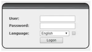
- Step 1: Log in the web setting page of Indoor Station
Input IP address of indoor station (e.g. http:// 172.18.90.14) into the address bar of PC’s web browser.
The default user name and password are both admin.
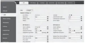
- Step 2:Add the SIP account
Set SIP server address, port, user name, password and SIP user with assigned SIP account parameters.
Select “Activate”, and then click Apply to save this setting.
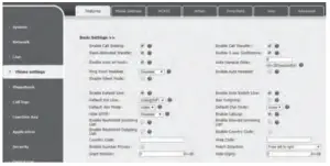
- Step 3: Feature Setting

- Step 4:Unlock Setting
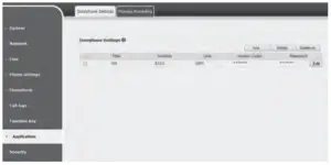
Application——Door phone Settings——Add——OK.
Title: Door Phone mode.
Number: The SIP account of Door Phone.
Line: The SIP line of Indoor Station.
Access codec: Consistent with the access code in door phone access table (The i56A as calling party)
Password: Same as open the door phone’s password (The i56A as called party)
Local Operation
- Answer/hang up calls
When the door phone calls the indoor station, click the button to answer the call, and click the
  button to hang up the call.
 - Unlock the door
During the call of indoor station and door phone, click the button to unlock the door.
 - Turn on/off the monitoring
Click the button on the indoor station to check the monitoring screen, and click the button again to exit. (Only support for the communication with video door phone)
 - Volume adjustment
When the indoor station is talking to other devices like door phone, click the button to increase the volume, and click the
  button to decrease the volume.


