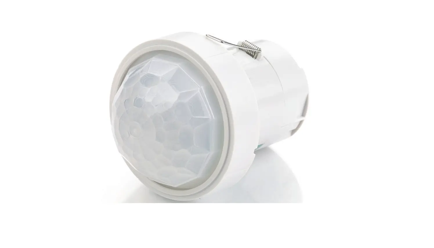
CP electronics EBDHS-PRM High Bay Presence Detectors Installation Guide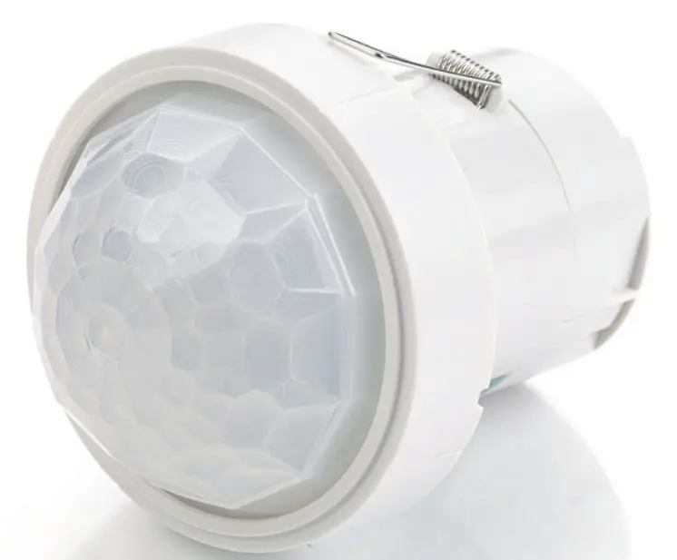
PRM switching, high bay
![]() Warning
Warning
This device should be installed by a qualified electrician in accordance with the latest edition of the IEE wiring regulations.
Downloads and Videos
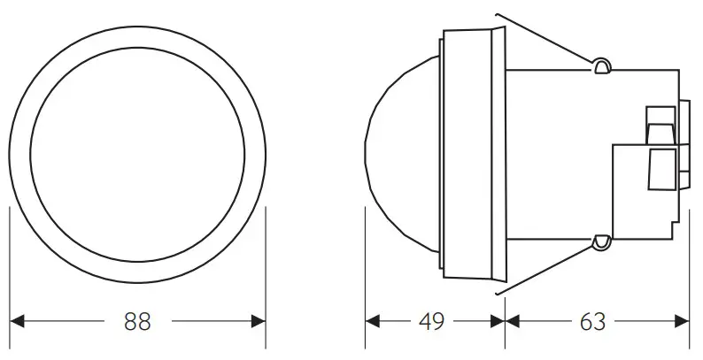
Dimensions (mm)
Wiring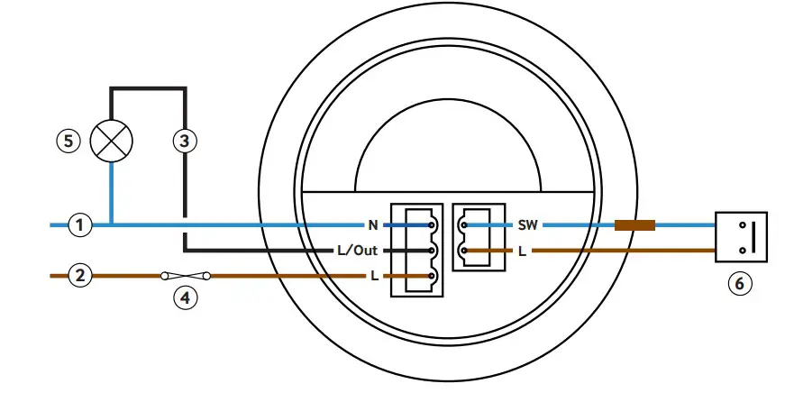
Key
- Neutral
- Live
- Switched output
- 10A circuit protection if required
- Load
- Momentary push-to-make switch, 230V (for absence detection)
Presence or absence detection
The unit ships with presence detection as default
- To change over to absence detection, press and release the external switch 5 times within the first minute of power up. The LED will turn on red for 30 seconds to indicate absence mode has been selected.
- To change back to presence detection, repeat the above procedure – the LED will flash red for 30 seconds to indicate presence mode has been selected.
To use absence detection a retractive (momentary) switch must be connected between the 2 terminals on the diagram. Note that this will be switching mains voltage.
Note: the above adjustments can also be made using the optional UHS5 or UNLCDHS handsets.
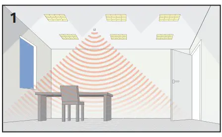
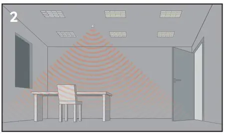
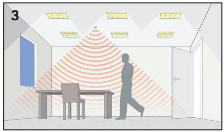
Detection pattern
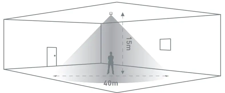
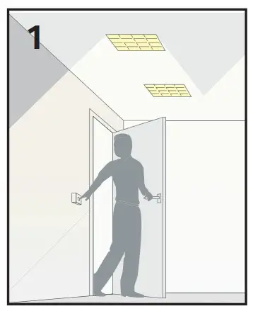
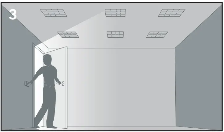
Walk acros
| Height | Range Diameter |
| 15m | 40m |
| 10m | 26m |
| 6m | 16m |
| 3m | 9m |
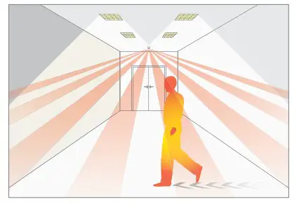
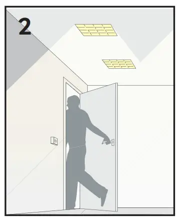
Walk towards|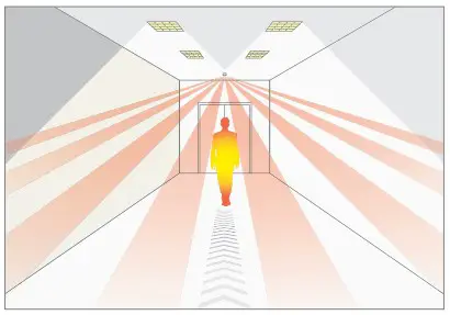
| Height | Range Diameter |
| 15m | 30m |
| 10m | 20m |
| 6m | 12m |
| 3m | 8m |
Walk towards & walk across explained
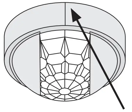
Alignment marks
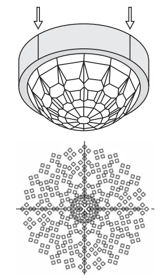
The sensor head has 4 alignment marks. These correspond to the 4 outer passive infrared sensors under the lens. Use these marks to align with aisles and corridors to ensure the best detection characteristics.
Masking shields
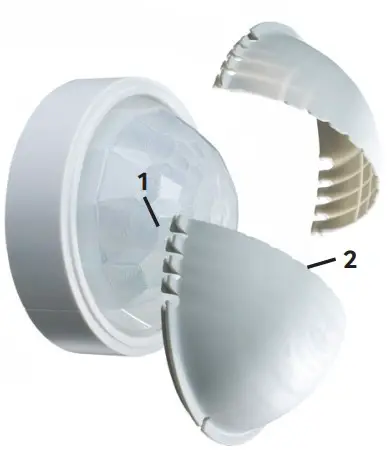
The detector includes two clip-on masking shields, enabling precise masking of the detection shape for aisles and corners as well as narrowing the detection diameter.
- Lateral trim pattern for slot style detection.
- Radial trim pattern for narrowing the detection diameter.
![]() Ensure all infra-red (IR) programming is completed before affixing the masking shields to the detector.
Ensure all infra-red (IR) programming is completed before affixing the masking shields to the detector.
Masking shield application
Aisles
Trim the masks laterally to reduce the detection width for aisles.
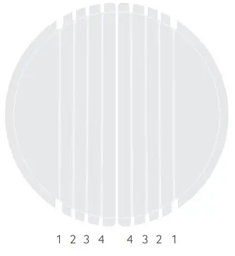
Key
- a. Trim line
- b. 15m Mounting height
- c. 10m Mounting height
- d. 6m Mounting height
- e. 3m Mounting height
- wa = walk across
- wt = walk towards
| a | B | c | d | e |
| 1 | wa 18m x 40m wt 13.5m x 30m | wa 11.7m x 26m wt 9m x 20m | wa 7.2m x 16m wt 5.4m x 12m | wa 4m x 9m wt 3.6m x 8m |
| 2 | wa 12.8m x 40m wt 9.6m x 30m | wa 8.3m x 26m wt 6.4m x 20m | wa 5.1m x 16m wt 3.8m x 12m | wa 2.8m x 9m wt 2.5m x 8m |
| 3 | wa 8.8m x 40m wt 6.6m x 30m | wa 5.7m x 26m wt 4.4m x 20m | wa 3.5m x 16m wt 2.6m x 12m | wa 1.9m x 9m wt 1.7m x 8m |
| 4 | wa 4.4m x 40m wt 3.3m x 30m | wa 2.8m x 26m wt 2.2m x 20m | wa 1.7m x 16m wt 1.3m x 12m | wa 0.9m x 9m wt 0.8m x 8m |
Install shields to detector
Align trimmed shields with sensor head alignment marks and aisle
Narrow detection
Trim the masks along radial lines to narrow the detection diameter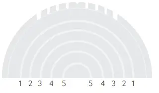
| a | B | c | d | e |
| 1 | wa 35.6m wt 26.7m | wa 23.1m wt 17.8m | wa 14.2m wt 10.6m | wa 8m wt 7.1m |
| 2 | wa 25.2m wt 18.9m | wa 16.3m wt 12.6m | wa 10m wt 7.5m | wa 5.6m wt 5m |
| 3 | wa 18m wt 13.5m | wa 11.7m wt 9m | wa 7.2m wt 5.4m | wa 4m wt 3.6m |
| 4 | wa 12.8m wt 9.6m | wa 8.3m wt 6.4m | wa 5.1m wt 3.8m | wa 2.8m wt 2.5m |
| 5 | wa 8.8m wt 6.6m | wa 5.7m wt 4.4m | wa 3.5m wt 2.6m | wa 1.9m wt 1.7m |
Key
- a. Trim line
- b. 15m Mounting height
- c. 10m Mounting height
- d. 6m Mounting height
- e. 3m Mounting height
- wa = walk across
- wt = walk towards
Install shields to detector
Installation
This device is designed to be flush ceiling-mounted. See page 20 for additional mounting options.
- Do not site the unit where direct sunlight might enter the sensor.
- Do not site the sensor within 1m of any lighting, forced air heating or ventilation.
- Do not fix the sensor to an unstable or vibrating surface.
Create cut out
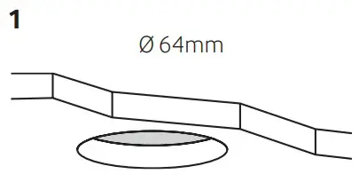
Cut a 64mm diameter hole in the ceiling
Wire stripping
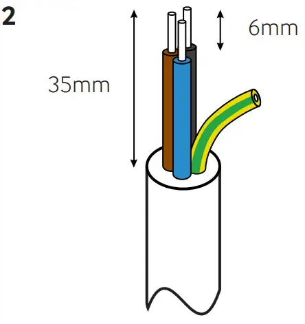
Strip the wires as shown opposite. Presence detector does not require earth conductor.
Wire in plugs & connect to detector
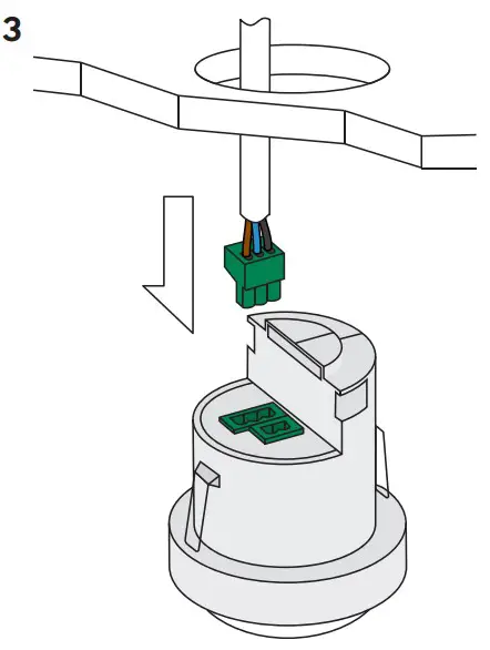
Wire in plug/s, using wiring diagram on page 2 as a guide. Connect the plug/s to the detector.
Clamp cable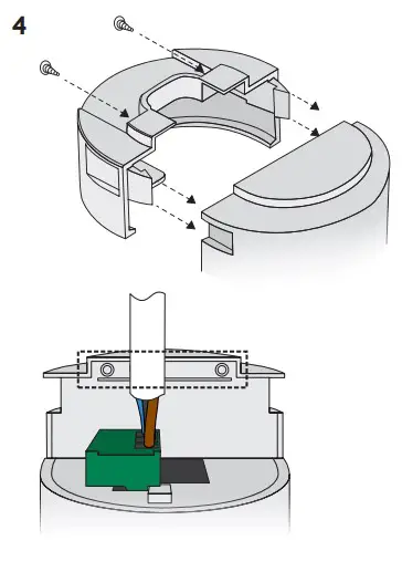
Continue tightening the screws until the clamp bar snaps out and is tightly engaged against the cable/s. The cable clamp must clamp the outer sheath only
Install detector
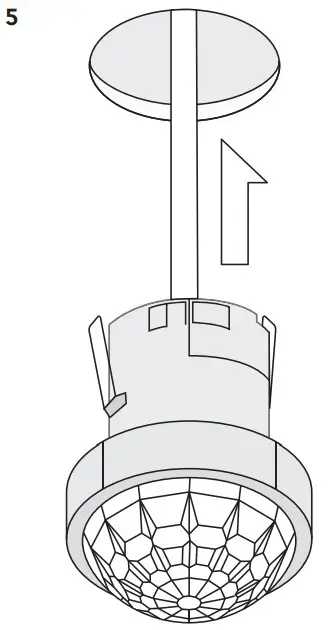
Bend the springs up and push detector through hole in ceiling. When fully inserted the springs snap back to hold the device in place.
![]() To avoid injury, take care when bending springs.
To avoid injury, take care when bending springs.
Default Settings
- Time out: 20 minutes.
- LUX on level: 9
- LUX off level: 9
- Sensitivity: 9
- Detection: Presence
Adjustments can be made using the optional UHS5 or UNLCDHS handsets.
Testing
Presence Detection
- Power up the sensor. The load should come on immediately.

- Vacate the room or remain very still and wait for the load to switch off (this should take less than 20 minutes).

- Enter the room or make some movement and check that the load switches on.

Absence Detection
- Power up the sensor. Switch the load on.

- Vacate the room and wait for the load to switch off (this should under than 20 minutes).

- Enter the room, the load will remain off until you switch it on again.

Technical Data
| Part code | EBDHS-PRM |
| Weight | 0.200kg |
| Supply voltage AC | 230 VAC +/- 10% |
| Supply frequency | 50Hz |
| Circuit protection | 10A |
| Power consumption parasitic | 847mW |
| Terminal capacity | 2.5mm² |
| Max load: | |
| Incandescent lighting | 10A |
| Fluorescent lighting | 10A |
| Compact fluorescent lighting | 10A |
| LED lighting | 10A |
| Resistive heaters | 10A |
| Fans and ventilation equipment | 10A |
| Time out range | 10 seconds to 99 minutes |
| Working temperature range | 10 to 35°C |
| Humidity | 5 to 95% noncondensing |
| Material (casing) | Flame retardant ABS and PC/ABS |
| Insulation class | 2 |
| IP rating | 40 |
| Compliance | EMC-2014/30/EU LVD-2014/35/EU |
This page is intentionally left blank
Accessories & associated products
| Part Numbe | Description |
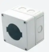
 DBB DBB | Surface mounting box |
 DBB-EXT DBB-EXT | Surface mount back box extender |
 EBD-ENCIP1 EBD-ENCIP1 | Pre-drilled 64mm hole IP65 detector enclosur |
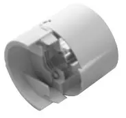 EXD-HSC EXD-HSC | Extended wiring housing |
 UHS5 UHS5 | Compact, programming |
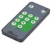 UHS7 UHS7 | Compact, user handset |
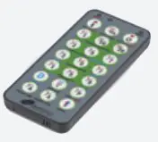
 UNLCDHS UNLCDHS | Universal LCD IR handset/commissioning handset |
CP Electronics
Brent Crescent, London NW10 7XR
t. +44 (0)333 900 0671
[email protected]
connect with us
Due to our policy of continual product improvement CP Electronics reserves the right to alter the specification of this product without prior notice.
WD407 Issue 11 Installation Guide, EBDHS-PR