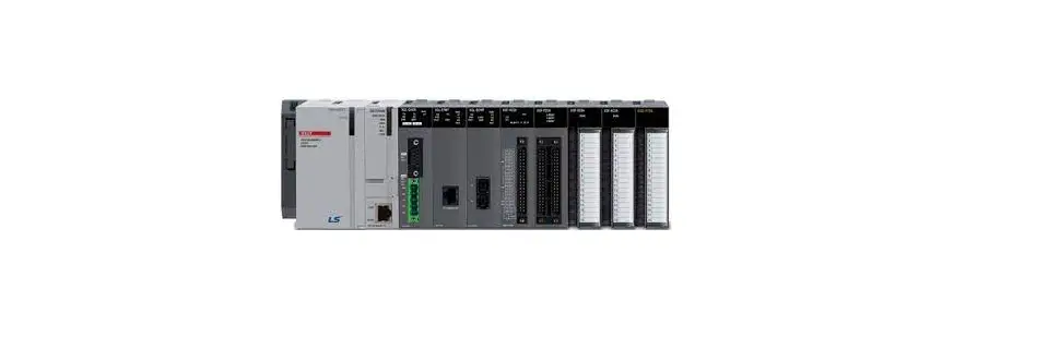
LS ELECTRIC XGT Dnet Programmable Logic Controller
Product Information
The product is a Programmable Logic Controller with the model number C/N: 10310000500. It uses XGT Dnet technology and has the XGL-DMEB model number. The PLC can be programmed for various functions and is suitable for industrial automation applications. The product has two input/output terminals and supports a range of protocols.
The text-extract from the user manual provides additional information about the product:
- Line 1: Indicates the name and model of the product.
- Line 2: Indicates the input/output configuration of the PLC.
- Line 3: Indicates a value of 55 for input/output terminal 1.
- Line 4: Indicates a value of -2570 for input/output terminal 2.
- Line 5: Indicates a value of 595%RH for input/output terminal 3 and 4.
Product Usage Instructions
To use the Programmable Logic Controller, follow the below steps:
- Connect the PLC to the power supply.
- Connect the input/output devices to the appropriate terminals as per the configuration mentioned in the user manual.
- Program the PLC using suitable software and programming languages as per the requirements of your application.
- Test the functionality of the PLC by running the programmed instructions and observing the input/output signals.
- Make necessary adjustments to the program or hardware connections as per the desired results.
Refer to the user manual for detailed information on programming and troubleshooting.change without notice due to continuous product development and improvement.
This installation guide provides simple function information or PLC control. Please read carefully this data sheet and manuals before using products. Especially read precautions then handle the products properly.
Safety Precautions
- Meaning of warning and caution label
WARNING: indicates a potentially hazardous situation which, if not avoided, could result in death or serious injury
CAUTION: indicates a potentially hazardous situation which, if not avoided, may result in minor or moderate injury. It may also be used to alert against unsafe practices
WARNING
- Do not contact the terminals while the power is applied.
- Be sure there are no foreign metallic matters.
- Do not manipulate the battery(charge, disassemble, hitting, short, soldering).
CAUTION
- Be sure to check the rated voltage and terminal arrangement before wiring
- When wiring, tighten the screw of terminal block with the specified torque range
- Do not install the flammable things on surroundings
- Do not use the PLC in the environment of direct vibration
- Except expert service staff, do not disassemble or fix or modify the product
- Use the PLC in an environment that meets the general specifications contained in this datasheet.
- Be sure that external load does not exceed the rating of output module.
- When disposing of PLC and battery, treat it as industrial waste.
- I/O signal or communication line shall be wired at least 100mm away from a high-voltage cable or power line.
Operating Environment
To install, observe the below conditions.
| No | Item | Specification | Standard | ||||
| 1 | Ambient temp. | 0 ~ 55℃ | – | ||||
| 2 | Storage temp. | -25 ~ 70℃ | – | ||||
| 3 | Ambient humidity | 5 ~ 95%RH, non-condensing | – | ||||
| 4 | Storage humidity | 5 ~ 95%RH, non-condensing | – | ||||
|
5 |
Vibration Resistance | Occasional vibration | – | – | |||
| Frequency | Acceleration | Amplitude |
IEC 61131-2 | ||||
| 5≤f<8.4㎐ | – | 3.5mm | 10 times in each direction for X, Y, Z | ||||
| 8.4≤f≤150㎐ | 9.8㎨(1g) | – | |||||
| Continuous vibration | |||||||
| Frequency | Frequency | Frequency | |||||
| 5≤f<8.4㎐ | – | 1.75mm | |||||
| 8.4≤f≤150㎐ | 4.9㎨(0.5g) | – | |||||
Applicable Support Software
For system configuration, the following version is necessary.
- XGI CPU: V3.9 or above
- XGK CPU: V4.5 or above
- XGR CPU: V2.6 or above
- XG5000 Software : V4.11 or above
Accessories and Cable Specifications
- Check DeviceNet Connector attached in the module
- Check terminal resistance contained in the box
1) Terminal resistance : 121Ω, 1/4W, allowance 1% (2EA) - When using DeviceNet communication channel, DeviceNet cable shall be used with consideration of communication distance and speed.
| Classification | Thick(class1) | Thick(class2) | Thin(class2) | Remark |
| Type | 7897A | 3082A | 3084A | Maker: Belden |
| Cable Type | Round | Trunk and Drop line is used concurrently | ||
| Impedance(Ω) | 120 | |||
| Temperature range(℃) | -20~75 | |||
| Max. allowable current(A) | 8 | 2.4 | ||
| Min. radius of curvature(inch) | 4.4 | 4.6 | 2.75 | |
| Core wire number | 5wires | |||
Parts Name and Dimension (mm)
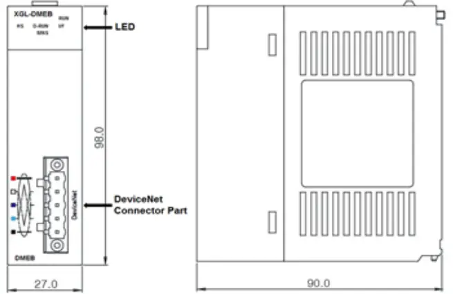
- This is front part of the Module. Refer to each name when operating the system. For more information, refer to user’s manual.
LED details
| LED | LED Status | Status | LED Description |
| RUN | On | Normal | Initialization |
| Off | Error | When a fatal error occurs | |
| I/F | Blink | Normal | Interface normal with CPU |
| Off | Error | Interface error with CPU | |
|
HS | On | Normal | HS Link normal operating state |
| Blink | Waiting | During parameter download through the config tool Communicate is stopped | |
| Off | Error | HS Link is disable When a fatal error occurs in HS Link | |
| D-RUN | Blink | Comm. Stop | Comm. Stop (Dnet I/F module and slave module) |
| On | Nromal | Normal operating (Dnet I/F module and slave module) | |
|
MNS | Off | Power Off | Dnet I/F module is net online -It has not completed the duplicate MAC ID test -may not be powered |
| Green blink | Waiting | Dnet I/F module is operational and online, no connection established -Device has passed the duplicate MAC ID check but has no established connection to other devices | |
| Green On | Normal | Completed connection setting and normal communication. | |
| Red blink | Error | In case recoverable error takes place I/O connection are in the time-out state | |
| Red On | Fatal Error | Dnet I/F module incapable to access to the network -Bus off because of heavy CAN faults. -Duplicate MAC ID detected. |
Installing / Removing Modules
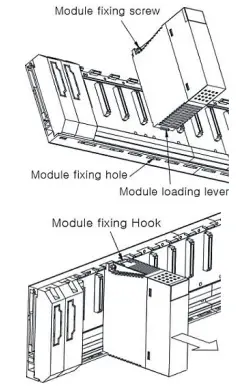
- Here describes the method to attach each module to the base or remove it.
- Installing module
- Insert a fixed projection of the lower part Of PLC into the module fixed hole of base
- Slide the upper part of module to fix to the base, and then fit it to the base by using the module fixed screw.
- Pull the upper part of module to check if it is installed to the base completely.
- Removing module
- Loosen the fixed screws of the upper part of module from the base
- By pressing the hook, pull the upper part of module from the axis of the lower part of module
- By lifting the module upward, remove the loading lever of module from the fixing hole
- Installing module
Wiring
- Wiring for communication
- 5 pin connector (for external connection)

- 5 pin connector (for external connection)
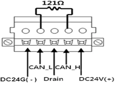
| Signal | Color | Service | 5 pin connector |
| DC 24V (+) | Red | Vcc | |
| CAN_H | White | Signal | |
| Drain | Bare | Shield | |
| CAN_L | Blue | Signal | |
| DC 24V (-) | Black | GND |
Warranty
- Warranty period: 18 months after the production date.
- Scope of Warranty: 18-month warranty is available except:
- The troubles caused by improper condition, environment or treatment except the instructions of LS ELECTRIC.
- The troubles caused by external devices
- The troubles caused by remodeling or repairing based on the user’s own discretion.
- The troubles caused by improper usage of the product
- The troubles caused by the reason which exceeded the expectation from science and technology level when LS ELECTRIC manufactured the product
- The troubles caused by natural disaster
- Change in specifications Product specifications are subject to change without notice due to continuous product development and improvement.
LS ELECTRIC Co., Ltd. www.ls-electric.com 10310000500 V4.5 (2021.11)
- E-mail: [email protected]
- Headquarter/Seoul Office
- LS ELECTRIC Shanghai Office (China)
- LS ELECTRIC (Wuxi) Co., Ltd. (Wuxi, China)
- LS-ELECTRIC Vietnam Co., Ltd. (Hanoi, Vietnam)
- LS ELECTRIC Middle East FZE (Dubai, U.A.E.)
- LS ELECTRIC Europe B.V. (Hoofddorf, Netherlands)
- LS ELECTRIC Japan Co., Ltd. (Tokyo, Japan)
- LS ELECTRIC America Inc. (Chicago, USA)
- Tel: 82-2-2034-4033,4888,4703
- Tel: 86-21-5237-9977
- Tel: 86-510-6851-6666
- Tel: 84-93-631-4099
- Tel: 971-4-886-5360
- Tel: 31-20-654-1424
- Tel: 81-3-6268-8241
- Tel: 1-800-891-2941
Factory: 56, Samseong 4-gil, Mokcheon-eup, Dongnam-gu, Cheonan-si, Chungcheongnam-do, 31226, Korea


